
Related Manuals for DIGITAL-LOGIC MICROSPACE MSMV104+


Summary of Contents for DIGITAL-LOGIC MICROSPACE MSMV104+
- Page 1 (217) 352-9330 | Click HERE Find the Microspace / Digital-Logic MSMV104+ at our website:...
- Page 2 TECHNICAL USER'S MANUAL FOR: PC/104 PERIPHERAL BOARD MSMV104+ Nordstrasse 11/F CH- 4542 Luterbach Tel.: ++41 (0)32 681 58 00 Fax: ++41 (0)32 681 58 01 Email: support@digitallogic.com Homepage: http://www.digitallogic.com Artisan Technology Group - Quality Instrumentation ... Guaranteed | (888) 88-SOURCE | www.artisantg.com...
- Page 3 DIGITAL-LOGIC AG MSMV104+ manual V1.0 COPYRIGHT Ó 1992- 2001 BY DIGITAL-LOGIC AG No part of this document may be reproduced, transmitted, transcribed, stored in a retrieval system, in any form or by any means, electronic, mechanical, optical, manual, or otherwise, without the prior written permission of DIGITAL-LOGIC AG.
-
Page 4: Table Of Contents
DIGITAL-LOGIC AG MSMV104+ manual V1.0 Table of Contents PREFACE..........................5 ........................5 OW TO USE THIS ANUAL ............................5 RADEMARKS ............................5 ISCLAIMER ......................5 HO SHOULD USE THIS RODUCT ........................6 ECYCLING NFORMATION ........................6 ECHNICAL UPPORT ..........................6 IMITED ARRANTY OVERVIEW ......................... 7 ........................7 RDERING NFORMATION ........................7... - Page 5 DIGITAL-LOGIC AG MSMV104+ manual V1.0 VESA S ......................25 UPER MODES ........................26 OW RESOLUTION MODES ...........................26 XTENDED MODES INDEX..........................28 Artisan Technology Group - Quality Instrumentation ... Guaranteed | (888) 88-SOURCE | www.artisantg.com...
-
Page 6: Preface
The specifications given in this manual were correct at the time of printing; advances mean that some may have changed in the meantime. If errors are found, please notify DIGITAL-LOGIC AG at the address shown on the title page of this document, and we will correct them as soon as possible. -
Page 7: Recycling Information
DIGITAL-LOGIC AG), wrong connection, wrong information or as a result of service or modification by anyone other than DIGITAL-LOGIC AG. Neither, if the user has not enough knowledge of these technologies or has not consulted the product manual or the technical support of DIGITAL-LOGIC AG and therefore the product has been damaged. -
Page 8: Overview
DIGITAL-LOGIC AG MSMV104+ manual V1.0 VERVIEW Ordering Information To get the actual status of the partnumbers, customers are advised to ask for them via our sales department or distributors. The list below has to be treated as a momentary screenshot and is might not up to date anymore. - Page 9 5 - 90% non condensing Vibration: 5 to 2000 Hz Shock: Temperature: Operating: Standard -25°C to +70°C version: Industry -25°C to +85°C version: (ask DIGITAL-LOGIC AG) Storage: -55°C to +85°C Artisan Technology Group - Quality Instrumentation ... Guaranteed | (888) 88-SOURCE | www.artisantg.com...
-
Page 10: Multimedia Features
DIGITAL-LOGIC AG MSMV104+ manual V1.0 Multimedia features The Lynx3DM motion compensation hardware allows full- frame playback of DVD content in software. Making use of its independent bus-master interface and its ability to alpha blend sub-picture data, the Lynx3DM offloads the CPU and eliminates the need for a dedicated decoder. -
Page 11: Connector And Jumper Description
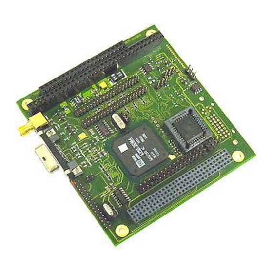
DIGITAL-LOGIC AG MSMV104+ manual V1.0 ONNECTOR AND JUMPER DESCRIPTION Product view The following picture shows a front view from MSMV104+ Version 1.0. The connectors references and position are the same on revision 1.2. The connector references are further explained in section 4.2 Figure 5.1a: Interface connectors on MSMV104+... -
Page 12: Dual Lcd Connector Signals
DIGITAL-LOGIC AG MSMV104+ manual V1.0 Type Molex MicroCross Digital/Analogue Reference TV-Out (CVBS) Type SMB Coax (75W f) Reference TV-Out (S-Video) Type Header 2 Reference ZV-Port Type Header 30 Reference Dual LCD connector signals The following table provides the pin to pin connection to the the LCD connector X1... -
Page 13: Lvds Connector Signals
DIGITAL-LOGIC AG MSMV104+ manual V1.0 The following table provides the pin to pin connection to the LCD connector X2 X2 Pin Signal X2 Pin Signal VDDSAVE (5V/1A) Shift Clock VBACKSAVE (12V/1A) Enable VEE (TTL) VCC Panel (5V/3,3V) No connection LVDS connector signals... -
Page 14: Zv-Port Connector Signals
DIGITAL-LOGIC AG MSMV104+ manual V1.0 ZV-Port connector signals The following table shows the signals, that are present on the ZV-Port connector J15 J15 Pin Signal J15 Pin Signal Clock Href Vref Blank DDC SDA DDC SCL No connection No connection... -
Page 15: Dvi Connector Signals
DIGITAL-LOGIC AG MSMV104+ manual V1.0 DVI connector signals For a mechanical front view of the connector, just consult next section. P2 Pin Signal P2 Pin Signal TX2- TX2+ SHIELD_GND DDC_SCL DDC_SDA VSYNC TX1- TX1+ SHIELD_GND MSEN TX0- TX0+ SHIELD_GND SHIELD_GND... -
Page 16: Jumper Descriptions
DIGITAL-LOGIC AG MSMV104+ manual V1.0 UMPER DESCRIPTIONS This chapter provides description for all the jumper present on MSMV104+. The sections which are red highlighted present jumper descriptions, which are only available for DVI/LVDS version of the product MSMV104+. 5.1 J7: LCD Bias power select. (2-jumper) -
Page 17: J25: Graphic Controller Mevdd Select (3-Jumper)
DIGITAL-LOGIC AG MSMV104+ manual V1.0 5.7 J25: graphic controller MEVDD select (3-jumper) J25 Pin J25 Pin MEVDD=2.5V MEVDD=3.3V 5.8 J26: graphic controller MIVDD select (3-jumper) J26 Pin J26 Pin MIVDD=2.5V MIVDD=3.3V 5.9 J27: graphic controller VCCA select (3-jumper) J27 Pin J27 Pin VCCA=2.5V... -
Page 18: 5.14 Dvi Connector Pin Description
DIGITAL-LOGIC AG MSMV104+ manual V1.0 5.14 DVI connector pin description The right part of the following figure shows the front view of the connector together with the pin description. The pin c5, which can be found in the previous section table is not represented and refers to the metal cross separating c1, c2 c3 and c4. -
Page 19: Dimensions, Connector And Jumper Locations
DIGITAL-LOGIC AG MSMV104+ manual V1.0 IMENSIONS CONNECTOR AND JUMPER LOCATIONS The following two figures show the dimension of the MSMV104+ V1.2, standard PC/104+ product. For the connector references please consult the dedicated chapter 5. Top view Figure 6.1a: Top view with connector references and dimensions of the board... -
Page 20: Bottom View
DIGITAL-LOGIC AG MSMV104+ manual V1.0 Bottom view Figure 6.1a: Bottom view with connector references Artisan Technology Group - Quality Instrumentation ... Guaranteed | (888) 88-SOURCE | www.artisantg.com... -
Page 21: Getting Started
DIGITAL-LOGIC AG MSMV104+ manual V1.0 ETTING STARTED This chapter is intended to show both the functionalities of the SMI chip and the way to access them under a windows operating system. Driver installation The first time that your new configuration will be started (both your CPU application board together with MSMV104+), you will be asked to install the correct driver for the SMI721 chip. -
Page 22: Accessing Chip Functionality Under Windows
DIGITAL-LOGIC AG MSMV104+ manual V1.0 Accessing chip functionality under Windows After the control panel be installed, you can access the extended display properties by clicking on the SMI icon to be found at the right bottom of your diplay Figure 8.3a: Location of the SMI icon for direct access to the extended display properties... -
Page 23: Choosing The Display Output
DIGITAL-LOGIC AG MSMV104+ manual V1.0 7.4.1 Choosing the display output The different available modes are listed below: CRT only mode LCD only mode Simultaneous mode (LCD+CRT) Dual display mode under windows with extension of the windows desktop on the second monitor... -
Page 24: 7.4.3 Entering Dual-Display Mode
DIGITAL-LOGIC AG MSMV104+ manual V1.0 Figure 8.4.2a: Setting hotkeys for the special display modes 7.4.3 Entering dual-display mode If two panel are configured, it is possible to use the dual display mode with the windows desktop extension. Right clicking on the second monitor icon and choosing to enable it will cause the whole windows desktop to be extended on two monitors. - Page 25 DIGITAL-LOGIC AG MSMV104+ manual V1.0 Figure 8.4.3b: Physical arrangement example one, second display on the left side Figure 8.4.3c Physical arrangement example two, second display over first display Artisan Technology Group - Quality Instrumentation ... Guaranteed | (888) 88-SOURCE | www.artisantg.com...
-
Page 26: Graphic Modes
DIGITAL-LOGIC AG MSMV104+ manual V1.0 RAPHIC MODES Standard IBM compatible VGA modes Standard IBM Compatible VGA Modes Mode Type Colors Alpha Resolution Font Clock Hsync Vsync Memory Buffer Page (MHz) (KHz) (Hz) (Min.) Start (Hex) 40x25 320x200 25.175 31.55 70.3... - Page 27 DIGITAL-LOGIC AG MSMV104+ manual V1.0 Low resolution modes Low Resolution Modes Mode # (Hex) Type Colors Resolutions Vsync (Hz) Video Memory Buffer Start 320x200 A0000 320x200 A0000 320x240 75, 60 A0000 320x240 75, 60 A0000 400x300 75, 60 A0000 400x300...
- Page 28 DIGITAL-LOGIC AG MSMV104+ manual V1.0 1024x768 Extended Modes Mode VESA Type Colors Alpha Font VCLK Hsync Vsync Video Buffer Mode # Format (MHz) +/- (KHz) Memory Start (Hex) (Hex) (Hz) 128x48 8x16 65.0 48.4 512KB A0000 128x48 8x16 65.0 48.4 A0000 78.75...
- Page 29 DIGITAL-LOGIC AG MSMV104+ manual V1.0 NDEX Multimedia................. 9 BIOS.................. 7 Bus ..................7 Power Supply..............7 Controller................. 7 Technical Support.............. 6 TV-Out................11 Display................8 DVI................8, 11 VGA................. 10 Video Memory ..............7 Interfaces................. 8 LCD ................. 10 ZV-Port................11 LVDS................
Need help?
Do you have a question about the MICROSPACE MSMV104+ and is the answer not in the manual?
Questions and answers