Huawei UPS5000-S Series User Manual
50 kva-300 kva
Hide thumbs
Also See for UPS5000-S Series:
- User manual (280 pages) ,
- Quick manual (16 pages) ,
- Quick manual (16 pages)

Related Manuals for Huawei UPS5000-S Series


Summary of Contents for Huawei UPS5000-S Series
- Page 1 UPS5000-S-(50 kVA-300 kVA) User Manual Issue Date 2020-12-07 HUAWEI TECHNOLOGIES CO., LTD.
- Page 2 Notice The purchased products, services and features are stipulated by the contract made between Huawei and the customer. All or part of the products, services and features described in this document may not be within the purchase scope or the usage scope. Unless otherwise specified in the contract, all statements, information, and recommendations in this document are provided "AS IS"...
-
Page 3: About This Document
Indicates a hazard with a high level of risk which, if not avoided, will result in death or serious injury. Indicates a hazard with a medium level of risk which, if not avoided, could result in death or serious injury. Issue 11 (2020-12-07) Copyright © Huawei Technologies Co., Ltd. - Page 4 Added SNMP descriptions to the sections about system settings and site configuration. Issue 07 (2019-10-16) Added description that the UPS5000 supports the mobile app function when it is powered on for the first time. Issue 06 (2019-08-20) Updated the monitoring UIs. Issue 11 (2020-12-07) Copyright © Huawei Technologies Co., Ltd.
- Page 5 Issue 03 (2018-02-01) Added the description of device application scenarios. Issue 02 (2017-10-30) Updated the output electrical specifications, product weight, and typical configuration. Issue 01 (2016-10-20) This issue is the first official release. Issue 11 (2020-12-07) Copyright © Huawei Technologies Co., Ltd.
-
Page 6: Table Of Contents
2.3.3 Bypass Module................................... 31 2.3.4 Control Module.................................. 34 2.3.4.1 Overview................................... 34 2.3.4.2 ECM..................................... 35 2.3.4.3 Dry contact card................................37 2.3.4.4 Monitoring interface card............................39 2.3.5 MDU....................................... 44 2.4 Typical configurations................................. 46 Issue 11 (2020-12-07) Copyright © Huawei Technologies Co., Ltd. - Page 7 3.2.11 Remote EPO................................... 121 3.2.12 Connecting Communications Cables........................122 3.3 Installing a Parallel System............................. 122 3.3.1 Installing the UPSs................................122 3.3.2 Connecting Power Cables.............................124 3.3.3 Connecting Signal Cables............................. 127 3.4 Installation Verification..............................129 Issue 11 (2020-12-07) Copyright © Huawei Technologies Co., Ltd.
- Page 8 4.3.5.3 UPS Alive Check Function............................216 5 Operations..........................219 5.1 Powering On and Starting the UPS..........................219 5.1.1 Powering On the UPS..............................219 5.1.2 Initial Startup..................................219 5.1.2.1 Obtaining Startup Password............................ 220 Issue 11 (2020-12-07) Copyright © Huawei Technologies Co., Ltd.
- Page 9 8.1 Physical Specifications..............................254 8.2 Internal Switch Parameters............................. 254 8.3 Environmental Specifications............................255 8.4 Safety Regulations and EMC............................255 8.5 Mains Input Electrical Specifications........................... 256 8.6 Bypass Input Electrical Specifications.......................... 256 Issue 11 (2020-12-07) Copyright © Huawei Technologies Co., Ltd. viii...
- Page 10 User Manual Contents 8.7 Battery Electrical Specifications............................. 257 8.8 Output Electrical Specifications............................. 258 8.9 System Electrical Specifications............................. 259 A (Optional) TN-C System Application................260 B Alarm List..........................264 C Acronyms and Abbreviations................... 277 Issue 11 (2020-12-07) Copyright © Huawei Technologies Co., Ltd.
-
Page 11: Safety Information
The "NOTICE", "CAUTION", "WARNING", and "DANGER" statements in this document do not cover all the safety instructions. They are only supplements to the safety instructions. Huawei will not be liable for any consequence caused by the violation of general safety requirements or design, production, and usage safety standards. - Page 12 ● Keep irrelevant people away from the equipment. Only operators are allowed to access the equipment. ● Use insulated tools or tools with insulated handles, as shown in the following figure. Issue 11 (2020-12-07) Copyright © Huawei Technologies Co., Ltd.
- Page 13 Do not change the structure or installation sequence of equipment without permission. ● Do not touch a running fan with your fingers, components, screws, tools, or boards before the fan is powered off or stops running. Issue 11 (2020-12-07) Copyright © Huawei Technologies Co., Ltd.
-
Page 14: Personnel Requirements
Do not power on the equipment before it is installed or confirmed by professionals. 1.2 Personnel Requirements ● Personnel who plan to install or maintain Huawei equipment must receive thorough training, understand all necessary safety precautions, and be able to correctly perform all operations. ●... - Page 15 0°C. Handle cables with caution, especially at a low temperature. – Cables stored at subzero temperatures must be stored at room temperature for at least 24 hours before they are laid out. Issue 11 (2020-12-07) Copyright © Huawei Technologies Co., Ltd.
-
Page 16: Installation Environment Requirements
Install the equipment in an area far away from liquids. Do not install it under areas prone to condensation, such as under water pipes and air exhaust vents, or areas prone to water leakage, such as air conditioner vents, ventilation Issue 11 (2020-12-07) Copyright © Huawei Technologies Co., Ltd. - Page 17 Any violations must be promptly pointed out by the site manager or safety supervisor and the involved personnel should be prompted for correction. Personnel who fail to stop violations will be forbidden from working. Issue 11 (2020-12-07) Copyright © Huawei Technologies Co., Ltd.
-
Page 18: Mechanical Safety
Ensure that the wider end of the ladder is at the bottom, or protective measures have been taken at the bottom to prevent the ladder from sliding. Issue 11 (2020-12-07) Copyright © Huawei Technologies Co., Ltd. - Page 19 D ANGER When removing a heavy or unstable component from a cabinet, be aware of unstable or heavy objects on the cabinet. ● Be cautious to avoid injury when moving heavy objects. Issue 11 (2020-12-07) Copyright © Huawei Technologies Co., Ltd.
-
Page 20: Device Running Safety
The UPS operating environment must meet the requirements for the climate indicator, mechanically active substance indicator, and chemically active substance indicator in ETSI EN 300 019-1 class 3.6. Issue 11 (2020-12-07) Copyright © Huawei Technologies Co., Ltd. - Page 21 UPS is connected to a backfeed protection card. Disconnect the backfeed protection card from the UPS before operating the UPS. Do not use the UPS in the following places: Issue 11 (2020-12-07) Copyright © Huawei Technologies Co., Ltd.
-
Page 22: Battery Safety
● Dispose of waste batteries in accordance with local laws and regulations. Do not dispose of batteries as household waste. If a battery is disposed of improperly, it may explode. Issue 11 (2020-12-07) Copyright © Huawei Technologies Co., Ltd. - Page 23 NO TICE To ensure battery safety and battery management accuracy, use batteries provided with the UPS by Huawei. Huawei is not responsible for any battery faults caused by batteries not provided by Huawei. Battery Installation Before installing batteries, observe the following safety precautions: ●...
- Page 24 Use batteries within the allowed temperature range; otherwise, the battery performance and safety will be compromised. ● Do not throw a lithium battery in fire. ● When maintenance is complete, return the waste lithium battery to the maintenance office. Issue 11 (2020-12-07) Copyright © Huawei Technologies Co., Ltd.
-
Page 25: Others
UPS output voltage level or frequency. Doing so may affect the power supply to equipment. ● Exercise caution when setting battery parameters. Incorrect settings will affect the power supply and battery lifespan. Issue 11 (2020-12-07) Copyright © Huawei Technologies Co., Ltd. -
Page 26: Overview
Routed from the top (only the UPS5000-S-300K-SMT model contains "T") This document describes the following UPS models: ● UPS5000-S-200K-SM/FM The models provide four configurations: 50 kVA, 100 kVA, 150 kVA, and 200 kVA. Issue 11 (2020-12-07) Copyright © Huawei Technologies Co., Ltd. -
Page 27: Working Principle
DC/DC converter. The UPS5000 converts inputs into pure high-quality sine wave outputs by using the high- frequency switching technology. Figure 2-2 UPS conceptual diagram Issue 11 (2020-12-07) Copyright © Huawei Technologies Co., Ltd. -
Page 28: Working Modes
The bypass power supply is not protected by the UPS which means it may be affected by mains outage, and incorrect AC voltage or frequency. Issue 11 (2020-12-07) Copyright © Huawei Technologies Co., Ltd. -
Page 29: Battery Mode
If the mains input is abnormal or the rectifier becomes abnormal, the UPS transfers to battery mode. The power module obtains DC power from batteries, and the power is converted into AC output by the inverter. Issue 11 (2020-12-07) Copyright © Huawei Technologies Co., Ltd. -
Page 30: Joint Power Mode
UPS transfers to joint power mode. In this case, the power module obtains energy from both the mains and batteries, and the energy is converted into AC outputs over the inverter. Issue 11 (2020-12-07) Copyright © Huawei Technologies Co., Ltd. -
Page 31: Maintenance Bypass Mode
2.2.2.5 Maintenance Bypass Mode When the UPS works in maintenance bypass mode, the current flows through the maintenance bypass instead of the power module. You can maintain the circuit inside the cabinet. Issue 11 (2020-12-07) Copyright © Huawei Technologies Co., Ltd. -
Page 32: Eco Mode
UPS transfers from bypass mode to normal mode. In bypass mode or normal mode, the rectifier keeps working and charges batteries using a charger. The ECO mode delivers a high efficiency. Issue 11 (2020-12-07) Copyright © Huawei Technologies Co., Ltd. -
Page 33: Product Introduction
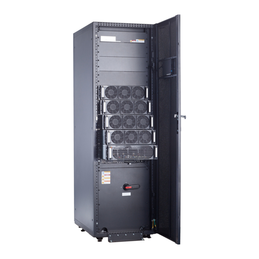
Figure 2-8 UPS conceptual diagram in ECO mode NO TE Manual startup is required to ensure that the inverter is in standby state and the power flow has reached the inverter. 2.3 Product Introduction 2.3.1 Structure Issue 11 (2020-12-07) Copyright © Huawei Technologies Co., Ltd. - Page 34 Figure 2-9 UPS5000-S-200K-SM front view (1) Power modules (2) Bypass module (3) Control module (4) Power distribution subrack cover (5) Filler panels (6) Monitor display (7) Maintenance (8) Folder unit bypass switch Issue 11 (2020-12-07) Copyright © Huawei Technologies Co., Ltd.
- Page 35 (2) Bypass input switch (3) Maintenance (4) Mains input switch subrack cover bypass switch (5) Output switch (6) Control module (7) Bypass module (8) Power modules (9) Monitor display (10) Folder (11) Filler panels unit Issue 11 (2020-12-07) Copyright © Huawei Technologies Co., Ltd.
- Page 36 (1) Cover (2) Mains input switch (3) Bypass input switch (4) Maintenance bypass switch (5) Output switch (6) Control module (7) Bypass module (8) Power modules (9) Monitor display (10) Folder unit Issue 11 (2020-12-07) Copyright © Huawei Technologies Co., Ltd.
- Page 37 Figure 2-12 UPS5000-S-300K-SM front view (1) Power modules (2) Bypass module (3) Control module (4) Power distribution subrack cover (5) Monitor display (6) Filler panels (7) Maintenance (8) Folder unit bypass switch Issue 11 (2020-12-07) Copyright © Huawei Technologies Co., Ltd.
- Page 38 2 Overview Figure 2-13 UPS5000-S-300K-SMT front view (1) Power distribution (2) Maintenance (3) Control module (4) Bypass module subrack cover bypass switch (5) Power modules (6) Monitor display (7) Filler panels unit Issue 11 (2020-12-07) Copyright © Huawei Technologies Co., Ltd.
- Page 39 UPS5000-S-(50 kVA-300 kVA) User Manual 2 Overview Figure 2-14 UPS5000-S-300K-SMT (isolation protection) front view (1) Cover (2) Maintenance (3) Control module (4) Bypass module bypass switch (5) Power modules (6) Monitor display unit Issue 11 (2020-12-07) Copyright © Huawei Technologies Co., Ltd.
-
Page 40: Power Module
The module is not configured, the short inverter or rectifier software is being intervals upgraded, or the inverter software is being upgraded (blinking at 4 Hz, on for 0.125s and off for 0.125s). Issue 11 (2020-12-07) Copyright © Huawei Technologies Co., Ltd. -
Page 41: Bypass Module
Weight: ≤ 35 kg ● Rated output capacity: 50 kVA/50 kW ● Power density: 50 kVA/3 U 2.3.3 Bypass Module Appearance Figure 2-16 shows a bypass module of a 200 kVA UPS. Issue 11 (2020-12-07) Copyright © Huawei Technologies Co., Ltd. - Page 42 (3) Run indicator (4) Alarm indicator (5) Fault indicator (6) Ready switch (7) Signal port (8) Input and output ports Figure 2-17 shows a bypass module of a 300 kVA UPS. Issue 11 (2020-12-07) Copyright © Huawei Technologies Co., Ltd.
- Page 43 The bypass software is being upgraded. Alarm Yellow Steady on A minor alarm is generated for the bypass. indicator There is no minor alarm for the bypass, or the software is being upgraded. Issue 11 (2020-12-07) Copyright © Huawei Technologies Co., Ltd.
-
Page 44: Control Module
Figure 2-18 Signal panel on the control module (1) Ground terminal (2) Parallel port 1 (3) BSC port 1 (4) Ready switch on ECM 1 Issue 11 (2020-12-07) Copyright © Huawei Technologies Co., Ltd. -
Page 45: Ecm
UPS systems, ensuring that two buses can switch with each other. BSC cables are hot-swappable. NO TE For a single UPS, the parallel cable is not needed. Issue 11 (2020-12-07) Copyright © Huawei Technologies Co., Ltd. - Page 46 Controls the running of a single UPS5000 and a parallel system, and reports the UPS5000 status information to other monitoring modules. ● The system provides three types of CAN communication: monitoring CAN communication, intra-rack parallel CAN communication, and inter-rack parallel CAN communication. Issue 11 (2020-12-07) Copyright © Huawei Technologies Co., Ltd.
-
Page 47: Dry Contact Card
Port for signal ground ● Disconnected: no battery grounding fault Port for detecting diesel ● Connected: D.G. Disconnecte generator (D.G.) mode mode ● Disconnected: Port for signal ground non-D.G. mode Issue 11 (2020-12-07) Copyright © Huawei Technologies Co., Ltd. - Page 48 STATUS_MT maintenance circuit circuit breaker breaker ● Connected: SWITCH Port for signal ground circuit breaker STATUS_0V SWITCH Port for monitoring the ● Connected: Connected STATUS_BP bypass input circuit circuit breaker breaker Issue 11 (2020-12-07) Copyright © Huawei Technologies Co., Ltd.
-
Page 49: Monitoring Interface Card
● In a parallel system, ensure that used dry contacts properly connect to each UPS. The monitoring interface card provides external ports as well as monitoring and control functions for the MDU. The ports include the ambient temperature and Issue 11 (2020-12-07) Copyright © Huawei Technologies Co., Ltd. - Page 50 B_TEMP Connects to an indoor battery temperature sensor port sensor. Southbound COM1 ● Supported protocol: Modbus-RTU. communications ● Connects to an ambient temperature and port 1 humidity sensor over two wires. Issue 11 (2020-12-07) Copyright © Huawei Technologies Co., Ltd.
- Page 51 ● RS485 cables and FE cables must be shielded cables. Figure 2-23 Figure 2-24 are recommended wiring methods for DO ports. Figure 2-23 Wiring method 1 Figure 2-24 Wiring method 2 Issue 11 (2020-12-07) Copyright © Huawei Technologies Co., Ltd.
- Page 52 UPS5000-S-(50 kVA-300 kVA) User Manual 2 Overview Figure 2-25 COM1 pins Table 2-8 COM1 pin definition Description RS485– RS485+ 12V_PORT Figure 2-26 COM2 pins Table 2-9 COM2 pin definition Description RS485+ RS485– Issue 11 (2020-12-07) Copyright © Huawei Technologies Co., Ltd.
- Page 53 UPS5000-S-(50 kVA-300 kVA) User Manual 2 Overview Description RS485+ RS485– CANH0 CANL0 Figure 2-27 RS485 pins Table 2-10 RS485 pin definition Description RS485_T+ RS485_T– RS485_R+ RS485_R– Issue 11 (2020-12-07) Copyright © Huawei Technologies Co., Ltd.
-
Page 54: Mdu
The UPS is running properly or a warning has been generated. The MDU is powered off. NO TE The indicator on the MDU panel is yellow when the bypass supplies power in non-ECO mode. Issue 11 (2020-12-07) Copyright © Huawei Technologies Co., Ltd. - Page 55 View or obtain UPS running information during preventive maintenance. NOTE Only Huawei service engineers or authorized service engineers are allowed to use the WiFi module. To ensure security, remove the WiFi module immediately after use.
-
Page 56: Typical Configurations
UPS are connected over parallel cables. The parallel connections synchronize the UPS outputs to supply power to loads. If one UPS fails, the other UPSs continue supplying power to loads. Issue 11 (2020-12-07) Copyright © Huawei Technologies Co., Ltd. -
Page 57: Dual-Bus System
An optional static transfer switch (STS) can be installed to start the bus synchronization controller (BSC). The UPS systems work in normal mode or bypass mode. Figure 2-31 Conceptual diagram of a dual-bus system Issue 11 (2020-12-07) Copyright © Huawei Technologies Co., Ltd. -
Page 58: Optional Components
Antiseismic Reinforces the cabinet so that the cabinet meets the requirements of 9 degree seismic fortification intensity. IP21 Prevents water from dropping into the cabinet, component protecting the cabinet to IP21. Issue 11 (2020-12-07) Copyright © Huawei Technologies Co., Ltd. - Page 59 Used for top air exhaust and allows the UPS to cabinet be installed against a wall. Cable entry If a cable entry cabinet is installed, cables can be cabinet routed in and out from the bottom of the cabinet. Issue 11 (2020-12-07) Copyright © Huawei Technologies Co., Ltd.
- Page 60 NO TE ● The ECM extended subrack does not support onsite installation. If you require this optional component, inform Huawei when you purchase the UPS. Huawei installs it before delivery. ● IP21 cannot be configured for the UPS5000-S-300K-SMT and UPS5000-S-200K-FM. If cables are routed in and out from the top for the UPS5000-S-200K-SM, IP21 cannot be configured.
-
Page 61: Installation
Ensure that the floor or installation support can bear the weight of the UPS5000, batteries, and battery racks. The weight of batteries and battery racks depends on the UPS configuration for the site. Issue 11 (2020-12-07) Copyright © Huawei Technologies Co., Ltd. -
Page 62: Installation Environment
The optimal operating temperatures for valve-regulated lead-acid batteries (VRLA batteries) are 20–30°C. Operating temperatures higher than 30°C shorten the battery lifespan and operating temperatures lower than 20°C reduce the battery backup time. Issue 11 (2020-12-07) Copyright © Huawei Technologies Co., Ltd. -
Page 63: Installation Clearances
Figure 3-2 Reserved clearances (unit: mm) 3.1.2 Tools and Instruments CA UTION Insulate installation tools to prevent electric shocks. Prepare the following tools and meters indicated in Table 3-1 for installation. Issue 11 (2020-12-07) Copyright © Huawei Technologies Co., Ltd. - Page 64 Electric hydraulic pliers Clamp meter Multimeter Cable tie Level instrument Polyvinyl chloride Cotton cloth Label Electrician's knife (PVC) insulation tape Electrostatic Protective gloves Insulated gloves Insulation discharge (ESD) protective shoes gloves Issue 11 (2020-12-07) Copyright © Huawei Technologies Co., Ltd.
-
Page 65: Preparing Power Cables
● The TN-C system is supported when the input N and PE are connected. Table 3-2 lists the recommended cross-sectional areas for power cables. Note that the currents listed are measured at a rated voltage of 380 V. Issue 11 (2020-12-07) Copyright © Huawei Technologies Co., Ltd. - Page 66 2 x (2 x 2 x (2 x 2 x (2 x 2 x (2 x d cross- 120) 150) 185) sectional area Batter Nominal battery y input discharge current (A) Issue 11 (2020-12-07) Copyright © Huawei Technologies Co., Ltd.
- Page 67 300 kVA: single-core 90°C soft power cable with a copper conductor. – It is recommended that the 200 kVA AC power cable should not be longer than 30 meters and the DC power cable should not be longer than 40 Issue 11 (2020-12-07) Copyright © Huawei Technologies Co., Ltd.
- Page 68 Crimped OT 10.5 mm 40 mm 26 N·m terminals Crimped OT 10.5 mm 30 mm 26 N·m terminals Table 3-5 lists the requirements for power cable terminals of the UPS5000- S-300K-SM/SMT. Issue 11 (2020-12-07) Copyright © Huawei Technologies Co., Ltd.
- Page 69 Mains input circuit breaker 400 A/3P Bypass input circuit breaker 400 A/3P Downstream output circuit 400 A/3P breaker UPS5000-S-300K- 250 kVA Mains input circuit breaker 630 A/3P SM/FMT Bypass input circuit breaker 400 A/3P Issue 11 (2020-12-07) Copyright © Huawei Technologies Co., Ltd.
-
Page 70: Unpacking And Checking
Step 1 Use a pallet truck to transport the UPS to the installation position. Step 2 Check the UPS packing. Step 3 Hold the sliding plate steady. Cut and remove the binding tapes. Put down the sliding plate gently. Issue 11 (2020-12-07) Copyright © Huawei Technologies Co., Ltd. - Page 71 Check that all fittings comply with the packing list. If some fittings are missing or do not comply with the packing list, record this information and contact your local Huawei office immediately. Step 7 Remove the L-shaped bracket that secures the cabinet and the pallet, and secure the sliding plate to the pallet by using the two M12 screws that were removed.
- Page 72 Step 8 Raise the four anchor bolts to the highest position using an adjustable wrench. Figure 3-6 Raising anchor bolts Step 9 Push the cabinet along the sliding plate to the floor. ----End Issue 11 (2020-12-07) Copyright © Huawei Technologies Co., Ltd.
-
Page 73: Installing A Single Ups
Step 2 Use a hammer drill to drill four holes for installing expansion bolts and then install four expansion bolts in the holes. Figure 3-8 shows the composition of an expansion bolt, and Figure 3-9 shows how to install an expansion bolt. Issue 11 (2020-12-07) Copyright © Huawei Technologies Co., Ltd. - Page 74 Partially tighten the expansion bolt and vertically insert it into the hole. Hit the expansion bolt using a rubber mallet until the expansion sleeve is fully inserted into the hole. Partially tighten the expansion bolt. Remove the bolt, spring washer, and flat washer. Issue 11 (2020-12-07) Copyright © Huawei Technologies Co., Ltd.
- Page 75 Step 5 Remove the rear panel of the cabinet, and then open the front door. Figure 3-10 Removing the rear panel Step 6 Remove the four plugs from the bottom of the cabinet (two at the front and two at the rear). Issue 11 (2020-12-07) Copyright © Huawei Technologies Co., Ltd.
- Page 76 Step 1 Adjust the four anchor bolts at the bottom of the UPS cabinet until all the four castors at the bottom hang in the air and the anchor bolts bear all of the cabinet weight, as shown in Figure 3-13. Issue 11 (2020-12-07) Copyright © Huawei Technologies Co., Ltd.
-
Page 77: Installing Batteries
● Install the batteries from the lower layer to the upper layer to prevent falling over due to imbalance. Procedure Step 1 Install a battery rack and batteries. For details, see the battery installation guide delivered along with batteries. ----End 3.2.3 Installing Optional Components Issue 11 (2020-12-07) Copyright © Huawei Technologies Co., Ltd. -
Page 78: Installing Antiseismic Kits
Step 2 Drill holes for installing expansion bolts, and install expansion bolts. Step 3 Secure two antiseismic kits to the front and rear of the cabinet: ● (With a marking-off template) use twelve M5x16 and four M12 screws. Issue 11 (2020-12-07) Copyright © Huawei Technologies Co., Ltd. - Page 79 Step 6 Secure antiseismic kits to the floor at both the front and rear of the cabinet by using eight M12 expansion bolts. The positioning is shown in Figure 3-17. Issue 11 (2020-12-07) Copyright © Huawei Technologies Co., Ltd.
-
Page 80: Installing An Ip21 Component
● Select the mounting holes for leveling feet based on the cabinet width onsite. Figure 3-18 Installing leveling feet Step 2 Secure the IP21 component to the top of each cabinet. Issue 11 (2020-12-07) Copyright © Huawei Technologies Co., Ltd. -
Page 81: Connecting An Ambient T/H Sensor
BCB box. For details, see the 0400, 0630) DC0384BXA BCB Box User Manual or PDU8000-(0125, 0250, 0400, 0630, 0800) DCV8-BXA001 BCB Box User Manual . Issue 11 (2020-12-07) Copyright © Huawei Technologies Co., Ltd. -
Page 82: Connecting The Bbb Box
Step 1 Install a battery grounding failure detector. For the installation method, see Battery Grounding Failure Detector User Manual . Figure 3-21 Position of a battery grounding failure detector in a UPS5000-S-200K- (1) Battery grounding failure detector Issue 11 (2020-12-07) Copyright © Huawei Technologies Co., Ltd. - Page 83 Figure 3-22 Position of a battery grounding failure detector in a UPS5000-S-200K- (1) Battery grounding failure detector Figure 3-23 Position of a battery grounding failure detector in a UPS5000-S-200K- FM (isolation protection) (1) Battery grounding failure detector Issue 11 (2020-12-07) Copyright © Huawei Technologies Co., Ltd.
- Page 84 Figure 3-24 Position of a battery grounding failure detector in a UPS5000-S-300K- (1) Battery grounding failure detector Figure 3-25 Position of a battery grounding failure detector in a UPS5000-S-300K- (1) Battery grounding failure detector Issue 11 (2020-12-07) Copyright © Huawei Technologies Co., Ltd.
-
Page 85: Connecting The Ibat
3.2.3.7 Connecting the iBAT Procedure Step 1 Connect the COM_OUT port on the CIM of the iBAT to the COM2 port on the monitoring interface card. Figure 3-27 COM2 port ----End Issue 11 (2020-12-07) Copyright © Huawei Technologies Co., Ltd. -
Page 86: Ups Cable Connection Reference
Choose an appropriate cabling route based on the actual situation. The figure is for reference only. Step 4 Connect the cable with a crimped terminal to the corresponding copper bar. Step 5 Clean foreign matter inside the cabinet. ----End Issue 11 (2020-12-07) Copyright © Huawei Technologies Co., Ltd. -
Page 87: Routing Cables (Ups5000-S-200K-Sm)
● When connecting battery cables, you do not need to connect neutral wires. Procedure Step 1 Ensure the maintenance bypass switch is OFF. Open the front door and remove the cover from the power distribution subrack. Figure 3-29 Removing the cover Issue 11 (2020-12-07) Copyright © Huawei Technologies Co., Ltd. - Page 88 N) Step 2 Remove the cable covers from the top of the cabinet. Figure 3-31 Removing the cable covers from the top of the cabinet Step 3 Connect ground cables. Issue 11 (2020-12-07) Copyright © Huawei Technologies Co., Ltd.
- Page 89 Figure 3-32 Ground cable NO TE ● : Internal equipotential connection ● : Protection ground Step 4 Route power cables. ● Dual mains Remove the copper bars between mains and bypass input terminals. Issue 11 (2020-12-07) Copyright © Huawei Technologies Co., Ltd.
- Page 90 Step 5 Route the signal cables on the left side of subracks along the left side of the cabinet and the cables on the right side of subracks along the right side of the cabinet, and then bind the cables to the cabinet, as shown in Figure 3-35. Issue 11 (2020-12-07) Copyright © Huawei Technologies Co., Ltd.
-
Page 91: Routing Cables From The Bottom
● Route cables for the UPS from inside out. ● When connecting battery cables, you do not need to connect neutral wires. Procedure Step 1 Open the front door and remove the cover from the power distribution subrack. Issue 11 (2020-12-07) Copyright © Huawei Technologies Co., Ltd. - Page 92 Remove all the cable cover for signal cables and small covers from the bottom. Remove the two large covers from the top of the cabinet, drill holes into them, and install them to the positions where the small covers were originally. Issue 11 (2020-12-07) Copyright © Huawei Technologies Co., Ltd.
- Page 93 The quantity of holes in the above figure is for reference only. ▪ If holes are drilled for routing cables, attach grommet strips on the hole edges to protect cables. Step 3 Connect ground cables. Issue 11 (2020-12-07) Copyright © Huawei Technologies Co., Ltd.
- Page 94 Step 4 Route power cables. ● Dual mains Remove the copper bars between mains and bypass input terminals. Figure 3-39 shows power cables routed from the bottom by removing small covers, as an example. Issue 11 (2020-12-07) Copyright © Huawei Technologies Co., Ltd.
- Page 95 Step 5 Route the signal cables on the left side of subracks along the left side of the cabinet and the cables on the right side of subracks along the right side of the cabinet, and then bind the cables to the cabinet, as shown in Figure 3-40. Issue 11 (2020-12-07) Copyright © Huawei Technologies Co., Ltd.
-
Page 96: Routing Cables (Ups5000-S-200K-Fm)
● Route cables for the UPS from inside out. ● When connecting battery cables, you do not need to connect neutral wires. Procedure Step 1 Open the front door and remove the cover from the power distribution subrack. Issue 11 (2020-12-07) Copyright © Huawei Technologies Co., Ltd. - Page 97 UPS5000-S-(50 kVA-300 kVA) User Manual 3 Installation Figure 3-41 Removing the cover Figure 3-42 Copper bar positions (1) Mains input terminals (1L1–1L3, N) (2) Bypass input terminals (2L1–2L3, N) Issue 11 (2020-12-07) Copyright © Huawei Technologies Co., Ltd.
- Page 98 Remove small covers from the top. Remove the two large covers from the rear top of the cabinet, drill holes into them, and install them to the positions where the small covers were placed. Issue 11 (2020-12-07) Copyright © Huawei Technologies Co., Ltd.
- Page 99 ● Prepare the OT terminals onsite to ensure that the length of the copper wire is the same as that of the part of the OT terminal that covers the conductor. Issue 11 (2020-12-07) Copyright © Huawei Technologies Co., Ltd.
- Page 100 Step 4 Route power cables. ● Dual mains Remove the copper bars between mains and bypass input terminals. Figure 3-46 Removing copper bars Figure 3-47 shows the cables routed from the top of the cabinet. Issue 11 (2020-12-07) Copyright © Huawei Technologies Co., Ltd.
- Page 101 Step 5 Route the signal cables on the left side of subracks along the left side of the cabinet and the cables on the right side of subracks along the right side of the cabinet, and then bind the cables to the cabinet. Issue 11 (2020-12-07) Copyright © Huawei Technologies Co., Ltd.
-
Page 102: Routing Cables From The Bottom
A cable entry cabinet is installed. Context NO TICE ● Route cables for the UPS from inside out. ● When connecting battery cables, you do not need to connect neutral wires. Issue 11 (2020-12-07) Copyright © Huawei Technologies Co., Ltd. - Page 103 Step 3 Adjust the anchor bolts of the cable entry cabinet to make it flush with the UPS cabinet. Step 4 Install equipotential plate mounting kits on the same horizontal plane of the UPS cabinet and cable entry cabinet. Issue 11 (2020-12-07) Copyright © Huawei Technologies Co., Ltd.
- Page 104 Figure 3-50 Equipotential plate mounting kit (1) Side panel (2) Cable trough Step 5 Place the cable entry cabinet on the right of the UPS cabinet. Step 6 Install the front and rear connecting kits. Issue 11 (2020-12-07) Copyright © Huawei Technologies Co., Ltd.
- Page 105 Step 9 Determine the cabling mode. ● Remove small covers for routing cables. Remove a certain number of small covers from the bottom of the cable entry cabinet based on the actual cable conditions. Issue 11 (2020-12-07) Copyright © Huawei Technologies Co., Ltd.
- Page 106 Remove the two large covers from the bottom of the cable entry cabinet, drill holes in them based on site requirements, and install them on the positions where the small covers were placed. Issue 11 (2020-12-07) Copyright © Huawei Technologies Co., Ltd.
- Page 107 – The quantity of holes in the above figure is for reference only. – If holes are drilled for routing cables, attach grommet strips on the hole edges to protect cables. Step 10 Connect the ground cables. Issue 11 (2020-12-07) Copyright © Huawei Technologies Co., Ltd.
- Page 108 Step 11 Connect power cables. ● Dual mains Remove the copper bars between mains and bypass input terminals. Figure 3-56 shows power cables routed from the bottom by removing small covers, as an example. Issue 11 (2020-12-07) Copyright © Huawei Technologies Co., Ltd.
- Page 109 For single mains, the copper bars between the mains and bypass input terminals do not need to be removed, and bypass input cables do not need to be connected. Step 12 Remove the signal cable trough cover from the cable entry cabinet. Issue 11 (2020-12-07) Copyright © Huawei Technologies Co., Ltd.
- Page 110 UPS5000-S-(50 kVA-300 kVA) User Manual 3 Installation Figure 3-57 Removing the cable trough cover Step 13 Connect the signal cable. Issue 11 (2020-12-07) Copyright © Huawei Technologies Co., Ltd.
-
Page 111: Routing Cables (Ups5000-S-200K-Fm, Isolation Protection)
Step 1 Ensure the maintenance bypass switch is OFF. Open the front door, remove the front cover, and remove covers from the top of the cabinet based on the site requirements. Issue 11 (2020-12-07) Copyright © Huawei Technologies Co., Ltd. - Page 112 Figure 3-60 Copper bar positions (1) Battery input terminals (+, –) (2) Output terminals (U, V, W, N) (3) Bypass input terminals (2L1–2L3, N) (4) Mains input terminals (1L1–1L3, N) Step 2 Connect ground cable. Issue 11 (2020-12-07) Copyright © Huawei Technologies Co., Ltd.
- Page 113 UPS5000-S-(50 kVA-300 kVA) User Manual 3 Installation Figure 3-61 Grounding Step 3 Route power cables. ● Dual mains Remove the copper bar between mains and bypass input terminals. Figure 3-62 Removing copper bars Issue 11 (2020-12-07) Copyright © Huawei Technologies Co., Ltd.
- Page 114 For single mains, the copper bar between the mains and bypass input terminals do not need to be removed, and bypass input cables do not need to be connected. Step 4 Route signal cables. Bind cables to the cabinet. Issue 11 (2020-12-07) Copyright © Huawei Technologies Co., Ltd.
-
Page 115: Routing Cables (Ups5000-S-300K-Sm)
● Route cables for the UPS from inside out. ● When connecting battery cables, you do not need to connect neutral wires. Procedure Step 1 Open the front door and remove the cover from the power distribution subrack. Issue 11 (2020-12-07) Copyright © Huawei Technologies Co., Ltd. - Page 116 (3) Mains input terminals –) (2L1–2L3, N) (1L1–1L3, N) (4) Output terminals (U, V, W, (5) Maintenance bypass switch and N) Step 2 Determine the cabling mode. ● Remove small covers for routing cables. Issue 11 (2020-12-07) Copyright © Huawei Technologies Co., Ltd.
- Page 117 Remove the two large covers from the top of the cabinet, drill holes into them, and install them to the positions where the small covers were placed. Figure 3-69 Hole positions Issue 11 (2020-12-07) Copyright © Huawei Technologies Co., Ltd.
- Page 118 Figure 3-70 Grounding NO TE ● : Internal equipotential connection ● : Protection ground Step 4 Route power cables. ● Dual mains Remove the copper bars between mains and bypass input terminals. Issue 11 (2020-12-07) Copyright © Huawei Technologies Co., Ltd.
- Page 119 UPS5000-S-(50 kVA-300 kVA) User Manual 3 Installation Figure 3-71 Removing copper bars Figure 3-72 shows the power cables routed from the bottom of the cabinet. Issue 11 (2020-12-07) Copyright © Huawei Technologies Co., Ltd.
- Page 120 Step 5 Route the signal cables on the left side of subracks along the left side of the cabinet and the cables on the right side of subracks along the right side of the cabinet, and then bind the cables to the cabinet, as shown in Figure 3-73. Issue 11 (2020-12-07) Copyright © Huawei Technologies Co., Ltd.
-
Page 121: Routing Cables (Ups5000-S-300K-Smt)
● When connecting battery cables, you do not need to connect neutral wires. Procedure Step 1 Ensure the maintenance bypass switch is OFF. Open the front door and remove the cover from the power distribution subrack. Issue 11 (2020-12-07) Copyright © Huawei Technologies Co., Ltd. - Page 122 (3) Battery input terminals (+, (1L1–1L3, N) (2L1–2L3, N) –) (4) Maintenance bypass switch (5) Output terminals (U, V, W, Step 2 Determine the cabling mode. ● Remove small covers for routing cables. Issue 11 (2020-12-07) Copyright © Huawei Technologies Co., Ltd.
- Page 123 Remove the two large covers from the rear top of the cabinet, drill holes into them, and install them to the positions where the small covers were placed. Figure 3-77 Hole positions Issue 11 (2020-12-07) Copyright © Huawei Technologies Co., Ltd.
- Page 124 Figure 3-78 Grounding NO TE ● : Internal equipotential connection ● : Protection ground Step 4 Route power cables. ● Dual mains Remove the copper bars between mains and bypass input terminals. Issue 11 (2020-12-07) Copyright © Huawei Technologies Co., Ltd.
- Page 125 UPS5000-S-(50 kVA-300 kVA) User Manual 3 Installation Figure 3-79 Removing copper bars Figure 3-80 shows the cables routed from the top of the cabinet. Issue 11 (2020-12-07) Copyright © Huawei Technologies Co., Ltd.
- Page 126 For single mains, the copper bars between the mains and bypass input terminals do not need to be removed, and bypass input cables do not need to be connected. Step 5 Route signal cables. Bind cables to the cabinet. Issue 11 (2020-12-07) Copyright © Huawei Technologies Co., Ltd.
-
Page 127: Routing Cables (Ups5000-S-300K-Smt, Isolation Protection)
Step 1 Ensure the maintenance bypass switch is OFF. Open the front door, remove the front cover, and remove covers from the top of the cabinet based on the site requirements. Issue 11 (2020-12-07) Copyright © Huawei Technologies Co., Ltd. - Page 128 Figure 3-83 Copper bar positions (1) Battery input terminals (+, –) (2) Bypass input terminals (2L1–2L3, N) (3) Mains input terminals (1L1–1L3, N) (4) Output terminals (U, V, W, N) Step 2 Connect ground cables. Issue 11 (2020-12-07) Copyright © Huawei Technologies Co., Ltd.
- Page 129 UPS5000-S-(50 kVA-300 kVA) User Manual 3 Installation Figure 3-84 Grounding Step 3 Route power cables. ● Dual mains Remove the copper bar between mains and bypass input terminals. Figure 3-85 Removing copper bars Issue 11 (2020-12-07) Copyright © Huawei Technologies Co., Ltd.
- Page 130 For single mains, the copper bar between the mains and bypass input terminals do not need to be removed, and bypass input cables do not need to be connected. Step 4 Route signal cables. Bind cables to the cabinet. Issue 11 (2020-12-07) Copyright © Huawei Technologies Co., Ltd.
-
Page 131: Remote Epo
----End 3.2.11 Remote EPO NO TICE ● Huawei does not provide the EPO switch or cable. If the cable is required, the recommended cable is 22 AWG. ● Equip the EPO switch with a protective cover to prevent misoperations, and cover the cable with protective tubing. -
Page 132: Connecting Communications Cables
Step 2 Connect the network port on a PC to the FE port of the monitoring interface card. ----End 3.3 Installing a Parallel System 3.3.1 Installing the UPSs Issue 11 (2020-12-07) Copyright © Huawei Technologies Co., Ltd. - Page 133 UPSs and then use screws to tighten the connecting kits to the cabinet according to the following figures: Figure 3-90 Installing connecting kits UPS5000-S-200K-SM and UPS5000-S-300K- Issue 11 (2020-12-07) Copyright © Huawei Technologies Co., Ltd.
-
Page 134: Connecting Power Cables
Step 2 Based on the site configurations, select a parallel connection method to connect cables for the parallel system. NO TE This document uses the number of oblique lines to indicate the number of power cables of the same type. Issue 11 (2020-12-07) Copyright © Huawei Technologies Co., Ltd. - Page 135 Connect power cables according to port silk screen. Figure 3-93 Cable connections for a 1+1 parallel system (1) Mains input power (2) Bypass input power (3) Battery cables (4) Output power cables cables cables Issue 11 (2020-12-07) Copyright © Huawei Technologies Co., Ltd.
- Page 136 Figure 3-94 Conceptual diagram of a dual-bus system Figure 3-95 Cable connections for a dual-bus system (1) Mains input power (2) Bypass input power (3) Battery cables (4) Output power cables cables cables ----End Issue 11 (2020-12-07) Copyright © Huawei Technologies Co., Ltd.
-
Page 137: Connecting Signal Cables
Figure 3-96 Topology diagram of an N+X parallel system NO TICE Figure 3-97 shows only control modules. Each control module represents a single UPS. Issue 11 (2020-12-07) Copyright © Huawei Technologies Co., Ltd. - Page 138 UPSs ● In a dual-bus system, you need to connect cables to BSC ports on the UPSs. Figure 3-98 shows the cable connections for a dual-bus system containing two master systems. Issue 11 (2020-12-07) Copyright © Huawei Technologies Co., Ltd.
-
Page 139: Installation Verification
UPS may be damaged. Table 3-7 Installation checklist Item Acceptance Criteria UPS installation The UPS is securely installed and does not tilt due to vibration. Issue 11 (2020-12-07) Copyright © Huawei Technologies Co., Ltd. - Page 140 3. There is no foreign matter around switch terminals. 4. There is no foreign matter on the bottom plate of the cabinet. 5. There is no foreign matter on the rear module subrack. Issue 11 (2020-12-07) Copyright © Huawei Technologies Co., Ltd.
- Page 141 3. Do not remove the dustproof cover before power-on to prevent dust inside the UPS. Figure 3-99 Positions for checking foreign matter (UPS5000-S-200K-FM) (1) Cabinet top (2) Wiring terminal (3) Switches (4) Rear of modules blocks Issue 11 (2020-12-07) Copyright © Huawei Technologies Co., Ltd.
- Page 142 UPS5000-S-(50 kVA-300 kVA) User Manual 3 Installation Figure 3-100 Positions for checking foreign matter (UPS5000-S-200K-FM, isolation protection) (1) Rear of modules (2) Cabinet top (3) Wiring terminal (4) Switches blocks Issue 11 (2020-12-07) Copyright © Huawei Technologies Co., Ltd.
- Page 143 UPS5000-S-(50 kVA-300 kVA) User Manual 3 Installation Figure 3-101 Positions for checking foreign matter (UPS5000-S-300K-SM) (1) Cabinet top (2) Wiring terminal (3) Cabinet bottom (4) Rear of modules blocks and switch Issue 11 (2020-12-07) Copyright © Huawei Technologies Co., Ltd.
- Page 144 Figure 3-102 Positions for checking foreign matter (UPS5000-S-300K-SMT, isolation protection) (1) Rear of modules (2) Cabinet top (3) Wiring terminal (4) Switches blocks Figure 3-103 Fill the holes with sealing putty (1) Paper protective film (2) Sealing putty Issue 11 (2020-12-07) Copyright © Huawei Technologies Co., Ltd.
- Page 145 UPS5000-S-(50 kVA-300 kVA) User Manual 3 Installation Figure 3-104 Dustproof cover Issue 11 (2020-12-07) Copyright © Huawei Technologies Co., Ltd.
-
Page 146: User Interface
The LCD screen is divided into three parts: status bar, alarm bar and information area. Figure 4-1 numerically labels functions of the default main screen, and Table 4-1 describes these functions. Figure 4-1 Main Menu screen Issue 11 (2020-12-07) Copyright © Huawei Technologies Co., Ltd. -
Page 147: System Info Screen
Returns to the upper-level menu. Logs a user out. 4.1.2 System Info Screen On the main screen, tap System Info. The System Info screen is displayed, as shown in Figure 4-2. Issue 11 (2020-12-07) Copyright © Huawei Technologies Co., Ltd. -
Page 148: Module Data Screen
Figure 4-3. Figure 4-3 Module Data screen 4.1.2.2 Running On the System Info screen, tap to access the Runn Info screen. Issue 11 (2020-12-07) Copyright © Huawei Technologies Co., Ltd. - Page 149 Table 4-3 AC output Item Description Phase voltage (V) AC output phase voltage Line voltage (V) AC output line voltage Phase current (A) AC output phase current Frequency (Hz) AC output frequency Issue 11 (2020-12-07) Copyright © Huawei Technologies Co., Ltd.
- Page 150 Mains input line voltage Phase current (A) Mains input phase current Frequency (Hz) Mains input frequency Power factor Proportion of the mains input active power to the mains input apparent power. Issue 11 (2020-12-07) Copyright © Huawei Technologies Co., Ltd.
- Page 151 Temperature (°C) (only for lithium batteries) Min Cell Temperature (°C) (only for lithium batteries) Table 4-8 Total runtime Item Description Bypass runtime (h) Time for which the UPS runs in bypass mode. Issue 11 (2020-12-07) Copyright © Huawei Technologies Co., Ltd.
-
Page 152: Alarms Screen
SOC, and SOH data of a single battery in the battery string. 4.1.2.3 Alarms Screen on the System Info screen to enter the Alarms screen. Figure 4-6 Alarms Screen Issue 11 (2020-12-07) Copyright © Huawei Technologies Co., Ltd. - Page 153 If the buzzer is enabled, Buzzer Off is displayed on the operation screen. Twinkle When the UPS communicates with the northbound NMS, the function determines the position of the UPS in the NMS layout diagram. Issue 11 (2020-12-07) Copyright © Huawei Technologies Co., Ltd.
-
Page 154: Settings
Figure 4-9 Settings 1 Figure 4-10 Settings 2 NO TE If the battery type is lead-acid battery, Settings is displayed on the iBOX Settings screen. Comm Settings Figure 4-11 Comm settings (lead-acid battery) Issue 11 (2020-12-07) Copyright © Huawei Technologies Co., Ltd. - Page 155 0. Table 4-10 Bitwise AND operation example PC IP address UPS IP address (182.98.225.125) (182.98.225.112) PC IP address/UPS IP 10110110.01100010.1 10110110.01100010.1 address 1100001.01111101 1100001.01110000 Subnet mask 11111111.11111111.1 11111111.11111111.1 (255.255.255.192) 1111111.11000000 1111111.11000000 Issue 11 (2020-12-07) Copyright © Huawei Technologies Co., Ltd.
- Page 156 NAT means network address Disable Disable, mapping translation. If it is set to Enable Disable, Internet cannot access IP addresses in local area network (LAN). Issue 11 (2020-12-07) Copyright © Huawei Technologies Co., Ltd.
- Page 157 When the UPS is connected over the serial port Modbus, set this parameter based on the frame format that the upstream device Modbus supports. Northbound Set the northbound protocol ModbusRTU ModbusRTU, protocol type type. Issue 11 (2020-12-07) Copyright © Huawei Technologies Co., Ltd.
- Page 158 Figure 4-16 Ambient temperature and humidity sensor Item Description Default Value Value Range Start address 32–44 Quantity Number of cascaded ambient 0–4 temperature and humidity sensors Issue 11 (2020-12-07) Copyright © Huawei Technologies Co., Ltd.
- Page 159 Default Value Value Range Start address 16–28 Quantity Number of cascaded battery 0–4 temperature sensors Figure 4-18 BMU Item Description Default Value Value Range Start address Quantity Number of cascaded BMUs 0–12 Issue 11 (2020-12-07) Copyright © Huawei Technologies Co., Ltd.
- Page 160 Password The password for accessing Changeme WiFi. Figure 4-20 SSH settings Item Description Default Value Value Range Enables or disables Secure Enable Disable, Shell (SSH) login. Enable Issue 11 (2020-12-07) Copyright © Huawei Technologies Co., Ltd.
- Page 161 SmartLi communication address address when the UPS queries SmartLi data. Start address Address for the NMS to obtain 0–124 for SmartLi- lithium battery data. communication System Settings Figure 4-22 System settings 1 Issue 11 (2020-12-07) Copyright © Huawei Technologies Co., Ltd.
- Page 162 Matches the system capacity. modules Redundant Set this parameter based on 0–19 modules load capacity and redundancy requirements. Working UPS working mode Normal mode Normal mode, mode ECO, Self-load mode, Converter mode Issue 11 (2020-12-07) Copyright © Huawei Technologies Co., Ltd.
- Page 163 Then the fan running status can be checked. Air filter Specifies the rack air filter 0–365 maintenance maintenance interval. If it is period (d) set to 0, there is no reminder. Issue 11 (2020-12-07) Copyright © Huawei Technologies Co., Ltd.
- Page 164 BCB trips if Indicates whether the BCB Enable Disable, UPS stops trips when the system stops Enable power supply supplying power and the output power is off. Input Settings Figure 4-25 Input settings Issue 11 (2020-12-07) Copyright © Huawei Technologies Co., Ltd.
- Page 165 Disable Disable, limiting or disable input current Enable limiting to protect generators. Input cur. Limits the input current to 50–200 limiting ratio protect the D.G. Output Settings Figure 4-26 Output settings Issue 11 (2020-12-07) Copyright © Huawei Technologies Co., Ltd.
- Page 166 (less than 20 ms) occurs when the UPS transfers from normal mode to bypass mode. If Output freq. track rate (Hz/s) is fast, the inverter frequency is unstable. Issue 11 (2020-12-07) Copyright © Huawei Technologies Co., Ltd.
- Page 167 (min) Enable, the UPS starts working after the time set for EOD restart delay when the input recovers from the power failure upon EOD. Bypass Settings Figure 4-27 Bypass settings Issue 11 (2020-12-07) Copyright © Huawei Technologies Co., Ltd.
- Page 168 ±2.0, ±3.0, range (Hz) and the rated frequency is ±4.0, ±5.0, ±6.0 greater than the specified value, the system determines that the bypass frequency is abnormal, so the bypass is unavailable. Issue 11 (2020-12-07) Copyright © Huawei Technologies Co., Ltd.
- Page 169 Figure 4-28 Battery settings (lead-acid battery) Figure 4-29 Battery settings (lithium battery) Item Description Default Value Value Range Battery type Type of batteries connected VRLA batt. VRLA batt., to the UPS. lithium batt. Issue 11 (2020-12-07) Copyright © Huawei Technologies Co., Ltd.
- Page 170 0.1C, 0.3C, 0.5C, and 1.0C Dis. cur. 0.3C 1.80 1.80–1.90 respectively. EOD (V/cell) Dis. cur. 0.5C 1.75 1.75–1.85 EOD (V/cell) Dis. cur. 1.0C 1.60 1.60–1.75 EOD (V/cell) Issue 11 (2020-12-07) Copyright © Huawei Technologies Co., Ltd.
- Page 171 Lithium battery: The charging 0.50 0.10–1.00 limiting coef. current limit is a multiple of the battery capacity. Lead-acid battery: The 0.10 0.05–0.15 charging current limit is a multiple of the battery capacity. Issue 11 (2020-12-07) Copyright © Huawei Technologies Co., Ltd.
- Page 172 Start address Specifies the communication 0–124 for iBOX-NMS address when the communicati northbound device queries iBOX data. iBOX number Specifies the number of 0–300 of iBATs iBATs managed by the iBOX. Issue 11 (2020-12-07) Copyright © Huawei Technologies Co., Ltd.
- Page 173 Multi-Hall (Single batt. group number cur. setting of hall≥ 1). Figure 4-33 Batt. String Config Set the iBOX and iBAT number for each battery string. Issue 11 (2020-12-07) Copyright © Huawei Technologies Co., Ltd.
- Page 174 BP/SYSMT Switch If the BP/SYSMT switch is set to Enable, the port has dry contact signal access. Using the port depends on the status of the BP/SYSMT switch. Issue 11 (2020-12-07) Copyright © Huawei Technologies Co., Ltd.
- Page 175 DO on the MUE07A. MUE07A DO_4, MUE07A DO_5 MUE07A DI_1, MUE07A DI_2, Corresponds to the signal of the input dry MUE07A DI_3, MUE07A DI_4, contact DI on the MUE07A. MUE07A DI_5 Issue 11 (2020-12-07) Copyright © Huawei Technologies Co., Ltd.
- Page 176 6–20 characters and contain at least two types of characters. NO TE Set the date and time as required. Issue 11 (2020-12-07) Copyright © Huawei Technologies Co., Ltd.
-
Page 177: Maintenance
Time Zone Figure 4-35 Time zone Set the local time zone. 4.1.2.5 Maintenance On the System Info screen, tap to display the Maintenance screen. Figure 4-36 Maintenance 1 Figure 4-37 Maintenance 2 Issue 11 (2020-12-07) Copyright © Huawei Technologies Co., Ltd. - Page 178 ● Do not perform battery maintenance when a D.G. is connected. Battery maintenance includes Forced Equalized Charging, Shallow Dis. Test, and Capacity Test. Figure 4-38 Battery Maint. (lead-acid battery) Figure 4-39 Battery Maint. (lithium battery) Issue 11 (2020-12-07) Copyright © Huawei Technologies Co., Ltd.
- Page 179 Starting or Shutting Down the Inverter Item Description Inv. ON The Inv. ON screen allows you to start the inverter manually. Inv. OFF The Inv. OFF screen allows you to shut down the inverter manually. Issue 11 (2020-12-07) Copyright © Huawei Technologies Co., Ltd.
- Page 180 Bus capacitor life forecast If the service life of a capacitor is about to end, that is, Module X bus capacitor life (y) is less than 1.0, contact Huawei technical support to replace the power module. Wizard Startup The wizard startup can be used to test the bypass, mains inverter, inverter/bypass switch, battery inverter, battery charging capability, battery switch tripping and so Perform operations as prompted.
-
Page 181: About Screen
4.1.2.6 About Screen On the System Info screen, tap About to view the UPS model, manufacturer name, monitoring version and power version. To view version details, tap Version Info. Issue 11 (2020-12-07) Copyright © Huawei Technologies Co., Ltd. -
Page 182: System Status
Figure 4-42 About screen 4.1.3 System Status On the System Status to view the mains input, bypass input, load, and battery information. Figure 4-43 System status 4.1.4 Common Functions Figure 4-44 Common functions 1 Issue 11 (2020-12-07) Copyright © Huawei Technologies Co., Ltd. -
Page 183: Webui
User name and Password, and click Login. NO TE The preset UPS IP address is 192.168.0.10. You can set the UPS Ethernet IP address on the LCD or WebUI. The value range is 1.0.0.0–223.255.255.255. Issue 11 (2020-12-07) Copyright © Huawei Technologies Co., Ltd. -
Page 184: Home
● It is advised to change the password after the first login using User Mgmt. on the Config. page to prevent unauthorized access. ----End 4.2.2 Home On the Home page, you can view the information about System Overview and Active Alarm. Figure 4-46 Home Issue 11 (2020-12-07) Copyright © Huawei Technologies Co., Ltd. -
Page 185: Monitoring
If Number of iBOXs is not 0 and the battery type is lead-acid Summary battery, Battery String Summary is displayed on the Monitoring sreen. Set parameters for the iBOX and iBAT connected to each battery string. Issue 11 (2020-12-07) Copyright © Huawei Technologies Co., Ltd. - Page 186 ECO function is enabled. ● If this parameter is set to Disable, the system is not allowed to enter ECO mode when the D.G. supplies power to the bypass. Issue 11 (2020-12-07) Copyright © Huawei Technologies Co., Ltd.
- Page 187 DGs, and DGs that are sensitive to the output reactive component. Input adaptability mode 2: It is applicable to the normal power grid and DGs, and input power sources with high internal resistance. Issue 11 (2020-12-07) Copyright © Huawei Technologies Co., Ltd.
- Page 188 LCD when the inverter cannot track the bypass frequency change. Normal power supply is not affected no matter whether this parameter is set to Enable or Disable. Issue 11 (2020-12-07) Copyright © Huawei Technologies Co., Ltd.
- Page 189 Capacitor failure detection upper limit and Capacitor failure detection lower limit. If the power module determines that the inverter capacitor is faulty, it shuts down the inverter to prevent the fault from expanding. Issue 11 (2020-12-07) Copyright © Huawei Technologies Co., Ltd.
- Page 190 (Charge/Discharge voltage – Average voltage)/Average voltage x 100%. The charge/discharge voltage and average voltage are obtained from the BMU. If the BMU is not configured, these two parameters do not need to be set. Issue 11 (2020-12-07) Copyright © Huawei Technologies Co., Ltd.
- Page 191 Equalized charging protection protection interval. After interval (d) equalized charging is complete, scheduled equalized charging starts when the non-equalized charging time exceeds Scheduled equalized charging interval. Issue 11 (2020-12-07) Copyright © Huawei Technologies Co., Ltd.
- Page 192 When a value exceeds the specified range, an alarm is generated. The calculation formula is (Charge/Discharge voltage – Issue 11 (2020-12-07) Copyright © Huawei Technologies Co., Ltd.
- Page 193 Class 1 grid Hibernation time for class 1 0–30 hiber. time power grids. Class 2 grid Hibernation time for class 2 0–15 hiber. time power grids. Issue 11 (2020-12-07) Copyright © Huawei Technologies Co., Ltd.
-
Page 194: Query
No. End number of an iBAT connected to the iBOX. 4.2.4 Query On the Query page, you can query Historical Alarm, Operation Log, and Performance Data, and perform Export Data. Issue 11 (2020-12-07) Copyright © Huawei Technologies Co., Ltd. -
Page 195: System Settings
Query the performance data of related components of the Data system. Export Data Export Historical Alarm, Active Alarm, Operation Log, and Performance Data. 4.2.5 System Settings Figure 4-49 System settings (lead-acid battery) Issue 11 (2020-12-07) Copyright © Huawei Technologies Co., Ltd. - Page 196 Export certificate file: Export the root certificate. Time Set the time zone and time for the site. Comm. Settings Set parameters such as IP Settings, RS485 Settings, ModbusTCP Settings, Amb. T/H Sensor. Issue 11 (2020-12-07) Copyright © Huawei Technologies Co., Ltd.
- Page 197 If SNMP Trap is incorrectly set or not set, system information will be lost or not reported in time. Event Notice ● Mailbox Settings: Set the email address of the recipient in Mailbox Settings. Issue 11 (2020-12-07) Copyright © Huawei Technologies Co., Ltd.
-
Page 198: Maintenance
On the Maintenance page, you can perform Soft Upgrade and User Management, query Version Information, query and export E-label, export Fault Information, and import and back up Configuration File. Figure 4-51 Maintenance Issue 11 (2020-12-07) Copyright © Huawei Technologies Co., Ltd. -
Page 199: Old Webui
User name and Password, and click Login. NO TE The preset UPS IP address is 192.168.0.10. You can set the UPS Ethernet IP address on the LCD or WebUI. The value range is 1.0.0.0–223.255.255.255. Issue 11 (2020-12-07) Copyright © Huawei Technologies Co., Ltd. - Page 200 ● After a user logs in to the WebUI, if another user logs in with the same user name, the current account will be logged out. ● It is advised to change the password after the first login using User Mgmt. on the Config. page to prevent unauthorized access. ----End Issue 11 (2020-12-07) Copyright © Huawei Technologies Co., Ltd.
-
Page 201: Monitoring
Menu bar Displays alarms and real-time data, sets parameters, and provides control commands. The Active Alarms page is displayed by default. Information Displays system monitoring information. area 4.3.2.1 Parameter Settings Issue 11 (2020-12-07) Copyright © Huawei Technologies Co., Ltd. - Page 202 EPO is performed only when this parameter is enabled and the EPO switch is triggered. When EPO detection is changed from Disable to Enable, check that the EPO cable is connected correctly. Issue 11 (2020-12-07) Copyright © Huawei Technologies Co., Ltd.
- Page 203 If Enable this parameter is set to Enable, the control chip RAM working status is checked regularly. If this parameter is set to Disable, regular check is disabled. Issue 11 (2020-12-07) Copyright © Huawei Technologies Co., Ltd.
- Page 204 In this mode, the total distortion of the input current waveform (THDi) is poor, but the system is stable. Weak input adaptability is suitable for mains and AC input sources. Issue 11 (2020-12-07) Copyright © Huawei Technologies Co., Ltd.
- Page 205 LCD when the inverter cannot track the bypass frequency change. Normal power supply is not affected no matter whether this parameter is set to Enable or Disable. Issue 11 (2020-12-07) Copyright © Huawei Technologies Co., Ltd.
- Page 206 Capacitor failure detection upper limit and Capacitor failure detection lower limit. If the power module determines that the inverter capacitor is faulty, it shuts down the inverter to prevent the fault from expanding. Issue 11 (2020-12-07) Copyright © Huawei Technologies Co., Ltd.
- Page 207 (Charge/Discharge voltage – Average voltage)/Average voltage x 100%. The charge/discharge voltage and average voltage are obtained from the BMU. If the BMU is not configured, these two parameters do not need to be set. Issue 11 (2020-12-07) Copyright © Huawei Technologies Co., Ltd.
- Page 208 Equalized charging protection protection interval. After interval (d) equalized charging is complete, scheduled equalized charging starts when the non-equalized charging time exceeds Scheduled equalized charging interval. Issue 11 (2020-12-07) Copyright © Huawei Technologies Co., Ltd.
- Page 209 Battery temperatures can be –5°C –20°C to +5°C alarm thresh. monitored in a timely (°C) manner. If a battery overtemperature alarm is detected, the charging current limit decreases to 0.03 CA. Battery charging Issue 11 (2020-12-07) Copyright © Huawei Technologies Co., Ltd.
- Page 210 Enable Enable and the remaining capacity is less than the warning threshold. Intelligent If this parameter is set to Disable Disable, hibernation Enable, the intelligent Enable battery hibernation function is enabled. Issue 11 (2020-12-07) Copyright © Huawei Technologies Co., Ltd.
-
Page 211: Communication Settings
Threshold, and the battery contact (V/ voltage is lower than this cell) threshold, the output dry contact will output signals. 4.3.2.2 Communication Settings Figure 4-54 Communication settings 4.3.2.3 Control Figure 4-55 Control 4.3.3 Query Issue 11 (2020-12-07) Copyright © Huawei Technologies Co., Ltd. -
Page 212: Historical Alarms
NO TE Historical logs can be exported but not queried. Figure 4-57 Logs 4.3.4 Config. 4.3.4.1 User Management On the home page, choose Config. > User Mgmt. Issue 11 (2020-12-07) Copyright © Huawei Technologies Co., Ltd. -
Page 213: Site Config
If the password complexity check is enabled, the user password is required to be a string of 6–20 characters and contain at least two types of characters. 4.3.4.2 Site Config. On the home page, choose Config. > Site Config. Issue 11 (2020-12-07) Copyright © Huawei Technologies Co., Ltd. - Page 214 Specify Email server IP address, Sender's email, and User account authentication required when sending a mail and click Test to check whether the test email can be received. Configure Alarm Notification Server Issue 11 (2020-12-07) Copyright © Huawei Technologies Co., Ltd.
-
Page 215: Rccmd
Enable upon first login. After you submit the setting, the page refreshes. The controls such as SSL Encrypted Transmission and Event Configuration will be displayed on the page, as shown in Figure 4-61. Figure 4-60 RCCMD function disabled Issue 11 (2020-12-07) Copyright © Huawei Technologies Co., Ltd. - Page 216 If it is set to Disable, the RCCMD certificate controls will not be displayed on the page, as shown in Figure 4-63. If SSL Encrypted Transmission is set to Disable, a message indicating there is a risk will be displayed. Issue 11 (2020-12-07) Copyright © Huawei Technologies Co., Ltd.
- Page 217 The MDU supports 17 alarm events, and a maximum of 50 jobs can be added for each event, as shown in Figure 4-64. Figure 4-64 shows the buttons on the Event Configuration page, and Table 4-22 describes these buttons. Figure 4-64 Event configuration page Issue 11 (2020-12-07) Copyright © Huawei Technologies Co., Ltd.
- Page 218 You can delete all jobs of the event by clicking this button. Figure 4-65 shows the buttons after one event is expanded and Table 4-23 describes these buttons. Figure 4-65 Buttons after one event is expanded Issue 11 (2020-12-07) Copyright © Huawei Technologies Co., Ltd.
- Page 219 Figure 4-66 RCCMD shutdown ● RCCMD Message: Specify the RCCMD client IP address, port, and message to be conveyed. The RCCMD client will receive the message. For example, enter "This is a test message". Issue 11 (2020-12-07) Copyright © Huawei Technologies Co., Ltd.
- Page 220 RCCMD client will receive the UPS input voltage value (for example, single-phase: 220 V; three-phase A: 220 V, B: 220 V, C: 220 V). Table 4-24 lists the signal names that can be entered. Issue 11 (2020-12-07) Copyright © Huawei Technologies Co., Ltd.
- Page 221 #TEMPDEG Temperature inside the Celsius #AUTONOMTIME Battery backup time minutes #STATUS UPS status #RUNTIME UPS operating time minutes #BATTVOLT Battery voltage #INFREQ Input frequency #BYPASSINFREQ Bypass input frequency #OUTFREQ Output frequency Issue 11 (2020-12-07) Copyright © Huawei Technologies Co., Ltd.
- Page 222 After the certificate is uploaded successfully, click Submit. The WebUI of the MDU will restart, and the uploaded certificate will be used for communication. Issue 11 (2020-12-07) Copyright © Huawei Technologies Co., Ltd.
-
Page 223: Managing The Ups By Using The Nms Complying With Rfc1628 Standard
MIB file which allows the third-party NMS to manage the UPS remotely. Figure 4-71 Download the MIB NO TE The UPS-RFC1628-MIB has more alarms than RFC1628. Download the UPS-RFC1628-MIB before using. Issue 11 (2020-12-07) Copyright © Huawei Technologies Co., Ltd. -
Page 224: Protecting The Server By Using The Rccmd Software
Configures and saves the address and port for receiving the shutdown command, and the message sending mechanism. For the method of installing the RCCMD client, see the manual related to the RCCMD. Issue 11 (2020-12-07) Copyright © Huawei Technologies Co., Ltd. -
Page 225: Rccmd Event Shutdown And Message Sending
RCCMD client at the same time to keep them the same. Enter the message to be sent and set the message sending mechanism. For example, set it to Immediately, once. Issue 11 (2020-12-07) Copyright © Huawei Technologies Co., Ltd. -
Page 226: Ups Alive Check Function
The default interval is 1800s and detection is performed 100 times, as shown in Figure 4-74. Issue 11 (2020-12-07) Copyright © Huawei Technologies Co., Ltd. - Page 227 UPS5000-S-(50 kVA-300 kVA) User Manual 4 User Interface Figure 4-74 Heartbeat detecting mode on the RCCMD client You can also manually detect heartbeat by clicking Run alive check now..Issue 11 (2020-12-07) Copyright © Huawei Technologies Co., Ltd.
- Page 228 UPS5000-S-(50 kVA-300 kVA) User Manual 4 User Interface Figure 4-75 Detecting heartbeat manually Figure 4-76 Detecting heartbeat manually and successfully ----End Issue 11 (2020-12-07) Copyright © Huawei Technologies Co., Ltd.
-
Page 229: Operations
Step 1 Close the upstream bypass and mains input switches. Step 2 (Full configuration model) Close the UPS bypass input switch, mains input switch, and output switch. After the UPS is powered on, initialization begins. The MDU displays the Huawei logo and an initialization progress bar. ----End 5.1.2 Initial Startup... -
Page 230: Obtaining Startup Password
Enter the generated password in the password text box on the LCD to start the inverter. ----End 5.1.2.2 Settings Wizard Procedure Step 1 Set the language, time, network parameters, system parameters, and battery parameters on the Settings Wizard screen. Issue 11 (2020-12-07) Copyright © Huawei Technologies Co., Ltd. - Page 231 ● Set Output frequency correctly; otherwise, loads may be affected and the UPS may not work properly. ● Battery parameter settings are critical to battery maintenance, battery lifespan, and UPS discharge time. Figure 5-1 Settings Wizard Issue 11 (2020-12-07) Copyright © Huawei Technologies Co., Ltd.
-
Page 232: Starting The Inverter
Starting the UPS on the MDU Step 1 Choose Common Functions > Inv. ON. NO TE You can also start the inverter by choosing System Info > Maintenance > Inv. ON. Issue 11 (2020-12-07) Copyright © Huawei Technologies Co., Ltd. - Page 233 Step 5 On the home page of the WebUI, choose Monitoring > UPS System > Running Control, click Inv. ON, and confirm the operation to start the inverter. Figure 5-3 Starting the inverter Issue 11 (2020-12-07) Copyright © Huawei Technologies Co., Ltd.
- Page 234 Step 4 Enter the correct user name and password and click Login. Step 5 On the home page of the WebUI, choose Monitoring > Control, click Inv. ON, and confirm the operation to start the inverter. Issue 11 (2020-12-07) Copyright © Huawei Technologies Co., Ltd.
-
Page 235: Powering On Loads
A BCB box is installed. Procedure Step 1 On the System Info > Settings > Dry Contact Set screen, set MUE05A connection to Enable, and set BCB connection [OL] and Battery breaker [STA] to Enable. Issue 11 (2020-12-07) Copyright © Huawei Technologies Co., Ltd. -
Page 236: Shutting Down And Powering Off The Ups
To shut down the inverter on the Maintenance screen, tap System Info > Maintenance. Figure 5-7 Normal bypass NO TE After you shut down the inverter, the Bypass mode alarm is displayed on the LCD. Issue 11 (2020-12-07) Copyright © Huawei Technologies Co., Ltd. -
Page 237: Starting The Ups In Battery Mode
Step 3 Use a multimeter to check that the voltage of battery strings at the UPS battery input terminal is greater than a certain value (single battery voltage x number of batteries in the battery string), which indicates that the batteries are connected properly. Issue 11 (2020-12-07) Copyright © Huawei Technologies Co., Ltd. -
Page 238: Transferring To Bypass Mode
Step 4 Press and hold down the BATT START button on the bypass module for at least 2 seconds. The system automatically enters the battery cold start status. The LCD displays the Huawei logo and an initialization progress bar. Step 5 After LCD initialization, start the inverter. -
Page 239: Testing Batteries
If the bypass is not normal, the inverter supplies power immediately. If the inverter is not started, the UPS may be disconnected. Figure 5-10 System status in ECO mode ----End 5.6 Testing Batteries Issue 11 (2020-12-07) Copyright © Huawei Technologies Co., Ltd. -
Page 240: Lead-Acid Battery Test
● The forced equalized charging test duration reaches the forced equalized charging protection time (12–24 h, 18 h by default). ● The UPS generates a battery overtemperature, overvoltage, or overcurrent alarm. ● An alarm is generated. ----End Issue 11 (2020-12-07) Copyright © Huawei Technologies Co., Ltd. -
Page 241: Shallow Discharge Test
Step 1 On the home screen of the LCD, choose System Info > Maintenance > Battery Maint. Step 2 Tap Start next to Shallow Dis. Test to start a shallow discharge test. Figure 5-12 Starting a shallow discharge test Issue 11 (2020-12-07) Copyright © Huawei Technologies Co., Ltd. -
Page 242: Capacity Test
Step 1 On the home screen of the LCD, choose System Info > Maintenance > Battery Maint. Step 2 Tap Start next to Capacity Test to start a capacity test. Figure 5-13 Starting a capacity test Issue 11 (2020-12-07) Copyright © Huawei Technologies Co., Ltd. -
Page 243: Lithium Battery Test
Manual Shallow Discharge Test On the home screen of the UPS LCD, choose System Info > Maintenance > Battery Maint. Tap Start next to Shallow Dis. Test to start a shallow discharge test. Issue 11 (2020-12-07) Copyright © Huawei Technologies Co., Ltd. -
Page 244: Capacity Test
Step 1 On the home screen of the UPS LCD, choose System Info > Maintenance > Battery Maint. Step 2 Tap Start next to Capacity Test to start a capacity test. Issue 11 (2020-12-07) Copyright © Huawei Technologies Co., Ltd. -
Page 245: Test Data Download
Export. ● Old Web On the WebUI, choose Query > Logs, choose logs that need to be exported from the Log drop-down list box, and click Query. Figure 5-17 Logs Issue 11 (2020-12-07) Copyright © Huawei Technologies Co., Ltd. -
Page 246: Transferring To Maintenance Bypass Mode
Step 1 Transfer the UPS to the bypass mode. Step 2 Close the maintenance bypass switch by performing the following actions according to the UPS version being used: Figure 5-18 Closing the maintenance bypass switch (UPS5000-S-200K-SM) Issue 11 (2020-12-07) Copyright © Huawei Technologies Co., Ltd. - Page 247 UPS5000-S-(50 kVA-300 kVA) User Manual 5 Operations Figure 5-19 Closing the maintenance bypass switch (UPS5000-S-200K-FM) Figure 5-20 Closing the maintenance bypass switch (UPS5000-S-200K-FM, isolation protection) Issue 11 (2020-12-07) Copyright © Huawei Technologies Co., Ltd.
- Page 248 UPS5000-S-(50 kVA-300 kVA) User Manual 5 Operations Figure 5-21 Closing the maintenance bypass switch (UPS5000-S-300K-SM) Figure 5-22 Closing the maintenance bypass switch (UPS5000-S-300K-SMT) Issue 11 (2020-12-07) Copyright © Huawei Technologies Co., Ltd.
-
Page 249: Transferring From Maintenance Bypass Mode To Normal Mode
The Maint. breaker misoperation and Maint. Breaker closed alarms disappear from the alarm list. Check whether the UPS works in bypass mode by viewing the system running status diagram on the LCD or WebUI. Issue 11 (2020-12-07) Copyright © Huawei Technologies Co., Ltd. -
Page 250: Performing Epo
Yes. The EPO alarm is cleared successfully. ● On the WebUI Choose Monitoring > UPS system > Running Control > Issued Order and click Clear Fault. The EPO alarm is cleared successfully. Issue 11 (2020-12-07) Copyright © Huawei Technologies Co., Ltd. -
Page 251: Exporting Data
Figure 5-25 Export Historical Data Click Export Historical Data and save the displayed webpage. Old Web Choose Query > Historical Alarms, and set Severity, Generated, and Cleared. Click Query to view the historical alarm information. Issue 11 (2020-12-07) Copyright © Huawei Technologies Co., Ltd. -
Page 252: Setting Hibernation Mode
On the WebUI, choose Monitoring > UPS System > Running Parameter > System Settings and set Paral sys hibernate to Enable. Set the module cycle hibernation period to an integer ranging from 1 to 100. The default value is 30. Issue 11 (2020-12-07) Copyright © Huawei Technologies Co., Ltd. - Page 253 Set the module cycle hibernation period to an integer ranging from 1 to 100. The default value is 30. Figure 5-28 System settings NO TE Click Submit after setting parameters on the WebUI. Issue 11 (2020-12-07) Copyright © Huawei Technologies Co., Ltd.
-
Page 254: Routine Maintenance
Customers are not allowed to maintain components behind protective covers that can be removed only using tools. If the components are to be maintained, contact Huawei technical support. ● Only maintenance engineers can maintain power modules and bypass modules. -
Page 255: Monthly Maintenance
Wipe the cabinet surface using Remove the dust, especially a white paper and the paper from the air filter on the front does not turn black. door, or replace the air filter. Issue 11 (2020-12-07) Copyright © Huawei Technologies Co., Ltd. -
Page 256: Annual Maintenance
The circuit breakers and ● Replace the circuit breaker through-current cables meet load breaker. capacity requirements. ● Replace the cable. The actual cable through-current capacity is greater than the circuit breaker specifications. Issue 11 (2020-12-07) Copyright © Huawei Technologies Co., Ltd. -
Page 257: Battery Maintenance
6.2.2 Monthly Maintenance Table 6-4 Monthly maintenance Item Expected Result Troubleshooting Battery No battery management Identify the cause of an alarm management alarm is generated. based on the alarm alarm information. Issue 11 (2020-12-07) Copyright © Huawei Technologies Co., Ltd. - Page 258 2. Check whether the equalized charging voltage and float charging voltage are correctly set for the UPS. 3. If the fault persists, contact Huawei technical support. Issue 11 (2020-12-07) Copyright © Huawei Technologies Co., Ltd.
-
Page 259: Quarterly Maintenance
3. If the fault persists, contact Huawei technical support. Issue 11 (2020-12-07) Copyright © Huawei Technologies Co., Ltd. -
Page 260: Annual Maintenance
(A torque wrench is used for checking the torque. After checking that the battery screws meet the requirements, mark the screws for later check.) Issue 11 (2020-12-07) Copyright © Huawei Technologies Co., Ltd. -
Page 261: Troubleshooting
EOD voltage and 11.3 V/cell. For details about how to rectify common faults, see Table 7-1. If any unmentioned faults occur, see the alarm list chapter, or contact Huawei technical support. Issue 11 (2020-12-07) Copyright © Huawei Technologies Co., Ltd. - Page 262 The buzzer is The bypass thyristor Replace the bypass bypass is activated, and the is damaged. module. Fault indicator is on. normal. Issue 11 (2020-12-07) Copyright © Huawei Technologies Co., Ltd.
- Page 263 Measure The bypass module Reduce the load, or experiences improve ventilation. overtemperature. NO TE For details about component replacement and maintenance involved in Troubleshooting and Alarm List, consult Huawei maintenance engineers. Issue 11 (2020-12-07) Copyright © Huawei Technologies Co., Ltd.
-
Page 264: Technical Specifications
Supports dry contacts, RS485 serial port, and FE port. Supports the Simple Network tion Management Protocol (SNMP). Weight 330 kg 440 kg 370 kg 450 kg 380 kg 460 kg 8.2 Internal Switch Parameters Issue 11 (2020-12-07) Copyright © Huawei Technologies Co., Ltd. -
Page 265: Environmental Specifications
When the altitude is greater than 1000 m and less than 4000 m, the rated power should be derated. For details, see the IEC62040-3. 8.4 Safety Regulations and EMC Item Specifications Safety EN62040-1: 2013 IEC62040-1: 2013 CQC3108-2011 YD/T2165-2017 Issue 11 (2020-12-07) Copyright © Huawei Technologies Co., Ltd. -
Page 266: Mains Input Electrical Specifications
Input PF ● > 0.99 (full load) ● > 0.98 (half load) THDi ● THDi ≤ 3% (full linear load) ● THDi < 5% (full non-linear load) 8.6 Bypass Input Electrical Specifications Issue 11 (2020-12-07) Copyright © Huawei Technologies Co., Ltd. -
Page 267: Battery Electrical Specifications
Maximum 32 A for a module Battery string sharing Battery string sharing is supported in a parallel system. No battery string is shared by default. Batteries with no neutral Supported wire Issue 11 (2020-12-07) Copyright © Huawei Technologies Co., Ltd. -
Page 268: Output Electrical Specifications
● Load > 150% or a short circuit occurs: run for 200 ms Bypass overload capability: ● At 30°C, load ≤ 135%: long-time operation ● At 40°C, load ≤ 125%: long-time operation ● Load > 1000%, run for 100 ms Issue 11 (2020-12-07) Copyright © Huawei Technologies Co., Ltd. -
Page 269: System Electrical Specifications
User Manual 8 Technical Specifications 8.9 System Electrical Specifications Item Specifications Redundancy design The auxiliary power supplies, centralized controllers, and parallel signals use redundancy design. ECO in a parallel system Supported Issue 11 (2020-12-07) Copyright © Huawei Technologies Co., Ltd. -
Page 270: A (Optional) Tn-C System Application
If the TN-C system is adopted, short-circuit the input N and PE. NO TE The following cable connections are for reference only. Figure A-1 Short-circuiting the input N and PE (UPS5000-S-200K-SM) Issue 11 (2020-12-07) Copyright © Huawei Technologies Co., Ltd. - Page 271 UPS5000-S-(50 kVA-300 kVA) User Manual A (Optional) TN-C System Application Figure A-2 Short-circuiting the input N and PE (UPS5000-S-200K-FM) Figure A-3 Short-circuiting the input N and PE (UPS5000-S-200K-FM, isolation protection) Issue 11 (2020-12-07) Copyright © Huawei Technologies Co., Ltd.
- Page 272 UPS5000-S-(50 kVA-300 kVA) User Manual A (Optional) TN-C System Application Figure A-4 Short-circuiting the input N and PE (UPS5000-S-300K-SM) Figure A-5 Short-circuiting the input N and PE (UPS5000-S-300K-SMT) Issue 11 (2020-12-07) Copyright © Huawei Technologies Co., Ltd.
- Page 273 User Manual A (Optional) TN-C System Application Figure A-6 Short-circuiting the input N and PE (UPS5000-S-300K-SMT, isolation protection) Table A-1 Recommended cross-sectional areas for cables Model Recommended Cross-Sectional Area UPS5000-S-200K-SM/FM UPS5000-S-300K-SM/SMT Issue 11 (2020-12-07) Copyright © Huawei Technologies Co., Ltd.
-
Page 274: B Alarm List
UPS5000-S-(50 kVA-300 kVA) User Manual B Alarm List Alarm List NO TE This table lists only common alarms. For more information, contact Huawei technical support. Alarm ID Alarm Name Severity Cause Solution (Alarm ID- Cause ID) 0001-1 Mains voltage Minor ●... - Page 275 ● The bypass 2. Check the voltage system input voltage is and bypass voltage not normal. thresholds configured on the LCD. Issue 11 (2020-12-07) Copyright © Huawei Technologies Co., Ltd.
- Page 276 The battery If the BCB box is configured, voltage reaches check whether the BCB box the EOD voltage trips. If it trips, close the BCB threshold due to box switch. continuous discharge. Issue 11 (2020-12-07) Copyright © Huawei Technologies Co., Ltd.
- Page 277 ● The charger is 3. If this alarm is generated faulty. in normal mode, check whether the battery switch is ON. If yes, the charger may be faulty. Replace the related power module. Issue 11 (2020-12-07) Copyright © Huawei Technologies Co., Ltd.
- Page 278 ● The actual number of batteries does not meet requirements. 0036-2 Battery Warning The time for Maintain the batteries. maintenance maintenance reminder arrives. Issue 11 (2020-12-07) Copyright © Huawei Technologies Co., Ltd.
- Page 279 1. Replace the fan. faulty. 2. Check the fan monitoring 0043-4 ● The fan cable. monitoring cable is faulty. 0047-1 Not ready Critical The ready switch Close the ready switch. is OFF. Issue 11 (2020-12-07) Copyright © Huawei Technologies Co., Ltd.
- Page 280 ● If all modules generate the alarm, open the bypass input circuit breaker. After the inverter relay is closed, close the bypass input circuit breaker 10 seconds later. Issue 11 (2020-12-07) Copyright © Huawei Technologies Co., Ltd.
- Page 281 2. Check that the module reduces the power is not derated due rated system to a fan fault. power. 3. If the alarm persists, ● The module is replace the power module. damaged. Issue 11 (2020-12-07) Copyright © Huawei Technologies Co., Ltd.
- Page 282 ● The intra-rack INVBYP cable is broken. ● The parallel CAN bus is broken. 0584-2 Inter-rack par. Minor The inter-rack Replace the inter-rack parallel cable alarm parallel cable is cable. faulty. Issue 11 (2020-12-07) Copyright © Huawei Technologies Co., Ltd.
- Page 283 Replace the dry contact board board fault communication MUE05A. with the dry contact board MUE05A fails. 0090-2 Replace the dry contact board communication MUE06A. with the dry contact board MUE06A fails. Issue 11 (2020-12-07) Copyright © Huawei Technologies Co., Ltd.
- Page 284 The running status is closed circuit breaker is displayed. No further measures are required. 0335 Generator Warning The generator is The running status is connected connected. displayed. No further measures are required. Issue 11 (2020-12-07) Copyright © Huawei Technologies Co., Ltd.
- Page 285 2. Check that bypass input the bypass and output power cables input or output on each rack meet the cables is length requirements. incorrect. 3. Rectify any bypass SCR ● The bypass SCR open-circuit. open-circuits. Issue 11 (2020-12-07) Copyright © Huawei Technologies Co., Ltd.
- Page 286 2. After maintenance, open the maintenance circuit breaker and then start the inverter. 0380 In self-check Warning The inverter is in Wait until the inverter self- self-check. check is complete. Issue 11 (2020-12-07) Copyright © Huawei Technologies Co., Ltd.
-
Page 287: C Acronyms And Abbreviations
American wire gauge bus synchronization controller BCB-BOX battery circuit breaker box BBB-BOX battery bus bar box control area network Conformite Europeenne economy control operation emergency power off energy control module end of discharge Issue 11 (2020-12-07) Copyright © Huawei Technologies Co., Ltd. - Page 288 RS485 Recommend Standard 485 SNMP Simple Network Management Protocol state of charge state of health static transfer switch Issue 11 (2020-12-07) Copyright © Huawei Technologies Co., Ltd.
- Page 289 User Manual C Acronyms and Abbreviations THDi total distortion of the input current waveform THDv total harmonic distortion of output voltage uninterruptible power system Universal Serial Bus VRLA valve-regulated lead acid battery Issue 11 (2020-12-07) Copyright © Huawei Technologies Co., Ltd.
Need help?
Do you have a question about the UPS5000-S Series and is the answer not in the manual?
Questions and answers