Huawei UPS5000-S User Manual
1200 kva
Hide thumbs
Also See for UPS5000-S:
- User manual (289 pages) ,
- Quick manual (16 pages) ,
- Quick manual (16 pages)

Related Manuals for Huawei UPS5000-S


Summary of Contents for Huawei UPS5000-S
- Page 1 UPS5000-S-1200 kVA User Manual Issue Date 2020-12-15 HUAWEI TECHNOLOGIES CO., LTD.
- Page 2 Notice The purchased products, services and features are stipulated by the contract made between Huawei and the customer. All or part of the products, services and features described in this document may not be within the purchase scope or the usage scope. Unless otherwise specified in the contract, all statements, information, and recommendations in this document are provided "AS IS"...
-
Page 3: About This Document
User Manual About This Document About This Document Purpose This document describes the UPS5000-S-1200 kVA in terms of its features, performance, working principles, appearance as well as instructions for installation, and operation and maintenance (O&M). Intended Audience This document is intended for: ●... - Page 4 Issue 06 (2020-01-15) Updated the installation procedure. Issue 05 (2019-12-20) Updated the safety information. Issue 04 (2019-06-25) Added the optional fan unit. Issue 03 (2019-04-02) Updated descriptions of installing communications cables. Issue 08 (2020-12-15) Copyright © Huawei Technologies Co., Ltd.
- Page 5 UPS5000-S-1200 kVA User Manual About This Document Issue 02 (2019-01-26) Updated the busbar installation sequence. Issue 01 (2018-05-30) This issue is the first official release. Issue 08 (2020-12-15) Copyright © Huawei Technologies Co., Ltd.
-
Page 6: Table Of Contents
2.3.3 Power Module..................................24 2.3.4 Bypass Module................................... 26 2.3.5 Control Module.................................. 28 2.3.5.1 Overview................................... 28 2.3.5.2 ECM..................................... 29 2.3.5.3 Dry Contact Card................................31 2.3.5.4 Monitoring Interface Card............................33 2.3.6 MDU....................................... 38 Issue 08 (2020-12-15) Copyright © Huawei Technologies Co., Ltd. - Page 7 3.4 Installation Verification...............................97 4 User Interface........................100 4.1 LCD Interface..................................100 4.1.1 Main Menu..................................100 4.1.2 Menu Hierarchy................................102 4.1.3 System Info..................................105 4.1.3.1 Running................................... 105 4.1.3.2 Alarms..................................... 110 4.1.3.3 Settings....................................111 4.1.3.4 Maintenance..................................138 Issue 08 (2020-12-15) Copyright © Huawei Technologies Co., Ltd.
- Page 8 5.5 Setting ECO Mode................................184 5.6 Testing Batteries..................................185 5.6.1 Lead-Acid Battery Test..............................185 5.6.1.1 Forced Equalized Charging Test..........................186 5.6.1.2 Shallow Discharge Test.............................. 187 5.6.1.3 Capacity Test................................. 188 5.6.2 Lithium Battery Test............................... 189 Issue 08 (2020-12-15) Copyright © Huawei Technologies Co., Ltd.
- Page 9 6.2.2 Monthly Maintenance..............................201 6.2.3 Quarterly Maintenance..............................202 6.2.4 Annual Maintenance..............................203 7 Troubleshooting........................205 8 Technical Specifications..................... 208 A (Optional) TN-C System Application................214 B Alarm List..........................215 C Acronyms and Abbreviations................... 228 Issue 08 (2020-12-15) Copyright © Huawei Technologies Co., Ltd. viii...
-
Page 10: Safety Information
The "NOTICE", "CAUTION", "WARNING", and "DANGER" statements in this document do not cover all the safety instructions. They are only supplements to the safety instructions. Huawei will not be liable for any consequence caused by the violation of general safety requirements or design, production, and usage safety standards. - Page 11 ● Keep irrelevant people away from the equipment. Only operators are allowed to access the equipment. ● Use insulated tools or tools with insulated handles, as shown in the following figure. Issue 08 (2020-12-15) Copyright © Huawei Technologies Co., Ltd.
- Page 12 Do not change the structure or installation sequence of equipment without permission. ● Do not touch a running fan with your fingers, components, screws, tools, or boards before the fan is powered off or stops running. Issue 08 (2020-12-15) Copyright © Huawei Technologies Co., Ltd.
-
Page 13: Personnel Requirements
Do not power on the equipment before it is installed or confirmed by professionals. 1.2 Personnel Requirements ● Personnel who plan to install or maintain Huawei equipment must receive thorough training, understand all necessary safety precautions, and be able to correctly perform all operations. ●... - Page 14 0°C. Handle cables with caution, especially at a low temperature. – Cables stored at subzero temperatures must be stored at room temperature for at least 24 hours before they are laid out. Issue 08 (2020-12-15) Copyright © Huawei Technologies Co., Ltd.
-
Page 15: Installation Environment Requirements
Install the equipment in an area far away from liquids. Do not install it under areas prone to condensation, such as under water pipes and air exhaust vents, or areas prone to water leakage, such as air conditioner vents, ventilation Issue 08 (2020-12-15) Copyright © Huawei Technologies Co., Ltd. - Page 16 Any violations must be promptly pointed out by the site manager or safety supervisor and the involved personnel should be prompted for correction. Personnel who fail to stop violations will be forbidden from working. Issue 08 (2020-12-15) Copyright © Huawei Technologies Co., Ltd.
-
Page 17: Mechanical Safety
Ensure that the wider end of the ladder is at the bottom, or protective measures have been taken at the bottom to prevent the ladder from sliding. Issue 08 (2020-12-15) Copyright © Huawei Technologies Co., Ltd. - Page 18 D ANGER When removing a heavy or unstable component from a cabinet, be aware of unstable or heavy objects on the cabinet. ● Be cautious to avoid injury when moving heavy objects. Issue 08 (2020-12-15) Copyright © Huawei Technologies Co., Ltd.
-
Page 19: Device Running Safety
The UPS operating environment must meet the requirements for the climate indicator, mechanically active substance indicator, and chemically active substance indicator in ETSI EN 300 019-1 class 3.6. Issue 08 (2020-12-15) Copyright © Huawei Technologies Co., Ltd. - Page 20 UPS is connected to a backfeed protection card. Disconnect the backfeed protection card from the UPS before operating the UPS. Do not use the UPS in the following places: Issue 08 (2020-12-15) Copyright © Huawei Technologies Co., Ltd.
-
Page 21: Battery Safety
● Dispose of waste batteries in accordance with local laws and regulations. Do not dispose of batteries as household waste. If a battery is disposed of improperly, it may explode. Issue 08 (2020-12-15) Copyright © Huawei Technologies Co., Ltd. - Page 22 NO TICE To ensure battery safety and battery management accuracy, use batteries provided with the UPS by Huawei. Huawei is not responsible for any battery faults caused by batteries not provided by Huawei. Battery Installation Before installing batteries, observe the following safety precautions: ●...
- Page 23 Use batteries within the allowed temperature range; otherwise, the battery performance and safety will be compromised. ● Do not throw a lithium battery in fire. ● When maintenance is complete, return the waste lithium battery to the maintenance office. Issue 08 (2020-12-15) Copyright © Huawei Technologies Co., Ltd.
-
Page 24: Others
UPS output voltage level or frequency. Doing so may affect the power supply to equipment. ● Exercise caution when setting battery parameters. Incorrect settings will affect the power supply and battery lifespan. Issue 08 (2020-12-15) Copyright © Huawei Technologies Co., Ltd. -
Page 25: Overview
1200 kVA Solution FusionPower The maximum capacity of UPS5000-S-1200 kVA-FP is 1200 kVA and it is compatible with a capacity of 1100 kVA, 990 kVA, 880 kVA, 770 kVA and 660 kVA. Issue 08 (2020-12-15) Copyright © Huawei Technologies Co., Ltd. -
Page 26: Working Principle
In normal mode, the rectifier converts AC power into DC power, then the inverter converts DC power into high-precision AC outputs. The conversions protect loads from interference such as input harmonics, glitches, and voltage transients. Issue 08 (2020-12-15) Copyright © Huawei Technologies Co., Ltd. -
Page 27: Bypass Mode
The bypass power supply is not protected by the UPS which means it may be affected by mains outage, and incorrect AC voltage or frequency. Figure 2-4 UPS conceptual diagram in bypass mode 2.2.2.3 Battery Mode Issue 08 (2020-12-15) Copyright © Huawei Technologies Co., Ltd. -
Page 28: Maintenance Bypass Mode
You can maintain the circuit inside the cabinet. Figure 2-6 UPS conceptual diagram in maintenance bypass mode Issue 08 (2020-12-15) Copyright © Huawei Technologies Co., Ltd. -
Page 29: Eco Mode
UPS transfers to joint power mode. In this case, the power module obtains energy from both the mains and batteries, and the energy is converted into AC outputs over the inverter. Issue 08 (2020-12-15) Copyright © Huawei Technologies Co., Ltd. -
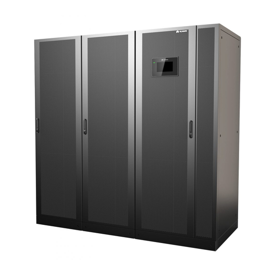
Page 30: Product Introduction
Figure 2-8 Conceptual diagram in joint power mode 2.3 Product Introduction 2.3.1 Appearance Figure 2-9 UPS (1) Power Unit 1 (2) Power Unit 2 (3) Bypass Unit (4) Input and output Unit Issue 08 (2020-12-15) Copyright © Huawei Technologies Co., Ltd. - Page 31 (optional) Figure 2-11 UPS+Fan unit (1) Fan unit – left (optional) (2) Power unit 2 (3) Power unit 1 (4) Bypass unit (5) Input/output unit (6) Fan unit – right (optional) Issue 08 (2020-12-15) Copyright © Huawei Technologies Co., Ltd.
-
Page 32: Product Structure
1 (Q5-1) 2 (Q5-2) (13) Bypass control (14) System output module switch (Q5) NO TE Modules in each power unit are numbered in ascending order, that is, module 1…, and module n. Issue 08 (2020-12-15) Copyright © Huawei Technologies Co., Ltd. -
Page 33: Power Module
2 Overview Figure 2-13 Maintenance bypass unit (optional) (1) Cover (2) Maintenance bypass switch Figure 2-14 Fan unit (optional) (1) Fan power switch (2) Cover stopper (3) Cover 2.3.3 Power Module Issue 08 (2020-12-15) Copyright © Huawei Technologies Co., Ltd. - Page 34 The module is not configured, the short intervals inverter or rectifier DSP software is being upgraded, or the inverter FPGA software is being upgraded (blinking at 4 Hz, on for 0.125s and off for 0.125s). Issue 08 (2020-12-15) Copyright © Huawei Technologies Co., Ltd.
-
Page 35: Bypass Module
Specifications ● Dimensions (H x W x D): 130 mm x 442 mm x 620 mm ● Weight: < 34 kg ● Rated output capacity: 55 kVA/55 kW 2.3.4 Bypass Module Issue 08 (2020-12-15) Copyright © Huawei Technologies Co., Ltd. - Page 36 (blinking at 4 Hz, on for 0.125s and off for 0.125s). The bypass CPLD software is being upgraded. Alarm Yellow Steady on A minor alarm is generated for indicator the bypass. Issue 08 (2020-12-15) Copyright © Huawei Technologies Co., Ltd.
-
Page 37: Control Module
NO TE The optional backfeed protection card or dry contact extended card can be installed only in the control module of the bypass unit. Issue 08 (2020-12-15) Copyright © Huawei Technologies Co., Ltd. -
Page 38: Ecm
The control module consists of two energy control modules (ECMs) in active/ standby mode. Figure 2-18 ECM Table 2-4 Ports on the ECM Silk Screen Description PARALLEL The PARALLEL port transmits parallel signals between racks. Issue 08 (2020-12-15) Copyright © Huawei Technologies Co., Ltd. - Page 39 Controls the running of a single UPS5000, and reports the UPS5000 status information to other monitoring modules. ● The system provides three types of CAN communication: monitoring CAN communication, intra-rack parallel CAN communication, and inter-rack parallel CAN communication. Specifications ● Hot-swappable Issue 08 (2020-12-15) Copyright © Huawei Technologies Co., Ltd.
-
Page 40: Dry Contact Card
Controls battery circuit ● 0 V: battery breaker trip. When the switch not voltage is +12 V, the tripped circuit breaker trips. ● 12 V: battery switch tripped BCB_0V Port for signal ground Issue 08 (2020-12-15) Copyright © Huawei Technologies Co., Ltd. - Page 41 ● Set the EPO port to NO or NC as required. ● Single cables require dual-insulated twisted cables. If the length of a power cable is within 25–50 m, its cross-sectional area must be 0.5 mm to 1.5 mm Issue 08 (2020-12-15) Copyright © Huawei Technologies Co., Ltd.
-
Page 42: Monitoring Interface Card
LCD. Figure 2-20 Monitoring interface card NO TE DO_1 to DO_4 meet the maximum voltage and current requirements of 30 V DC/1 A or 60 V DC/0.5 A. Issue 08 (2020-12-15) Copyright © Huawei Technologies Co., Ltd. - Page 43 Southbound COM2 Reserved ● Supported protocol: communications Modbus-RTU. port 2 ● Connects to a southbound device, such as an iBattery. Issue 08 (2020-12-15) Copyright © Huawei Technologies Co., Ltd.
- Page 44 0.5–1.5 mm ● RS485 cables and FE cables must be shielded cables. Figure 2-21 Figure 2-22 are recommended wiring methods for DO ports. Figure 2-21 Wiring method 1 Issue 08 (2020-12-15) Copyright © Huawei Technologies Co., Ltd.
- Page 45 UPS5000-S-1200 kVA User Manual 2 Overview Figure 2-22 Wiring method 2 Figure 2-23 COM1 pins Table 2-8 COM1 pin definition Description RS485– RS485+ 12V_PORT Issue 08 (2020-12-15) Copyright © Huawei Technologies Co., Ltd.
- Page 46 User Manual 2 Overview Figure 2-24 COM2 pins Table 2-9 COM2 pin definition Description RS485+ RS485– RS485+ RS485– CANH0 CANL0 Figure 2-25 RS485 pins Table 2-10 RS485 pin definition Description RS485_T+ Issue 08 (2020-12-15) Copyright © Huawei Technologies Co., Ltd.
-
Page 47: Mdu
RS485–. 2.3.6 MDU Appearance Figure 2-26 MDU (1) Status indicator (2) LCD touchscreen Table 2-11 Status indicator Status Color Meaning A critical alarm has been generated, and the buzzer sounds continuously. Issue 08 (2020-12-15) Copyright © Huawei Technologies Co., Ltd. - Page 48 The indicator on the MDU panel is yellow when the bypass supplies power in non-ECO mode. Figure 2-27 MDU ports Table 2-12 Description of MDU ports Port Name Description MUS05A Connects to the MDU and monitoring interface card (DB26) Network port Reserved RS485_1 Reserved Issue 08 (2020-12-15) Copyright © Huawei Technologies Co., Ltd.
-
Page 49: Typical Configurations
View or obtain UPS running information during preventive maintenance. NOTE Only Huawei service engineers or authorized service engineers are allowed to use the WiFi module. To ensure security, remove the WiFi module immediately after use. -
Page 50: Single Ups
UPS are connected over parallel cables. The parallel connections synchronize the UPS outputs to supply power to loads. If one UPS fails, the other UPSs continue supplying power to loads. Issue 08 (2020-12-15) Copyright © Huawei Technologies Co., Ltd. -
Page 51: Single Ups Dual-Bus System
(STS) can be installed to start the bus synchronization controller (BSC). The UPS systems work in normal mode or bypass mode. The conceptual diagram uses a dual-bus system with a single UPS as an example. Issue 08 (2020-12-15) Copyright © Huawei Technologies Co., Ltd. -
Page 52: Optional Components
● PDU8000-0800DCV remote trip control. 8-BXA001 PDU8000-(0630, 1250, BBB box ● PDU8000-1250DCV Converges the energy from 2000) DCV8-BGA001 BBB 8-BGA001 multiple battery strings. Box User Manual ● PDU8000-2000DCV 8-BGA001 Issue 08 (2020-12-15) Copyright © Huawei Technologies Co., Ltd. - Page 53 Fan unit The fan unit is used for top air exhaust. Install this subrack when expansion the UPS is equipped with a subrack backfeed protection card and dry contact expansion card. Issue 08 (2020-12-15) Copyright © Huawei Technologies Co., Ltd.
- Page 54 2 Overview NO TE The ECM expansion subrack does not support onsite installation. If you require this optional component, inform Huawei when you purchase the UPS so that Huawei can install the subrack before delivery. Issue 08 (2020-12-15) Copyright © Huawei Technologies Co., Ltd.
-
Page 55: Installation
The optimal operating temperatures for valve-regulated lead-acid batteries (VRLA batteries) are 20–30°C. Operating temperatures higher than 30°C shorten the battery lifespan and operating temperatures lower than 20°C reduce the battery backup time. 3.1.1.2 Installation Clearances Issue 08 (2020-12-15) Copyright © Huawei Technologies Co., Ltd. - Page 56 Figure 3-1 UPS reserved clearances (unit: mm) Figure 3-2 UPS+Maintenance bypass unit reserved clearances (unit: mm) Figure 3-3 UPS+Fan unit reserved clearances (unit: mm) Reserve the following clearances around the cabinet to facilitate operations and ventilation: Issue 08 (2020-12-15) Copyright © Huawei Technologies Co., Ltd.
-
Page 57: Tools And Instruments
Hammer drill and Hand-held Alloy hole saw Heat gun drill bit Φ16 electric drill Diagonal pliers Crimping tools Wire stripper Electric hydraulic pliers Clamp meter Multimeter Cable tie Level instrument Issue 08 (2020-12-15) Copyright © Huawei Technologies Co., Ltd. - Page 58 M16) NO TE Table 3-1 lists only the common tools for installation and cable connection. For more dedicated tools required, see the corresponding component manuals. Prepare tools based on site requirements. Issue 08 (2020-12-15) Copyright © Huawei Technologies Co., Ltd.
-
Page 59: Preparing Power Cables And Copper Bars
(1) The area marked by the line box is reserved for dense busway. (2) No power distribution box (PDB) or cabling is allowed inside the area marked by the line box. Issue 08 (2020-12-15) Copyright © Huawei Technologies Co., Ltd. - Page 60 Table 3-2 Recommended cross-sectional areas for power cables Item Specifications Mains input Mains input current (A) 2420 Bypass Bypass input current (A) 2000 input Output Output current (A) 2000 Battery Battery nominal discharge current 2632 input (VRLA battery) Issue 08 (2020-12-15) Copyright © Huawei Technologies Co., Ltd.
- Page 61 – Routing mode: The cables are routed over a ladder or bracket in a single layer (E in IEC60364-5-52). The distance between cables should be Issue 08 (2020-12-15) Copyright © Huawei Technologies Co., Ltd.
- Page 62 Mains input circuit breaker 2500 A/3P Bypass input circuit breaker 2500 A/3P Downstream output circuit The system has a general output switch. breaker There is no need to add an external circuit breaker. Issue 08 (2020-12-15) Copyright © Huawei Technologies Co., Ltd.
-
Page 63: Unpacking
Step 1 Use a pallet truck to transport the UPS to the installation position. Step 2 Remove the UPS outer packing. Step 3 Remove the bolts that secure the UPS to the pallet and remove the UPS from the pallet. Issue 08 (2020-12-15) Copyright © Huawei Technologies Co., Ltd. -
Page 64: Optional) Splitting The Bypass Unit And Input And Output Unit
Screw Specification Quantity (PCS) PE copper bar M12x35 N, L1, L2 and L3 M12x45 copper bars U, V and W copper M12x45 bars Top epoxy plate M8x20 Bottom epoxy plate M6x30 Issue 08 (2020-12-15) Copyright © Huawei Technologies Co., Ltd. - Page 65 Step 3 Remove the PE, N, L1, L2 and L3 copper bars. Figure 3-8 Remove copper bars Step 4 Remove cable terminal, U, V and W copper bars and epoxy plate. Issue 08 (2020-12-15) Copyright © Huawei Technologies Co., Ltd.
- Page 66 Step 5 Remove the top, middle, and bottom connecting plates in sequence from the bypass unit and input and output unit. NO TICE Use a step ladder to remove the top connecting plates as the cabinet is high. Issue 08 (2020-12-15) Copyright © Huawei Technologies Co., Ltd.
-
Page 67: Optional) Combining The Bypass Unit And Input And Output Unit
Step 4 Check that the bypass unit and input and output unit are combined completely and securely. Step 5 After checking that cabinets are combined properly, reinstall the rear covers. ----End Issue 08 (2020-12-15) Copyright © Huawei Technologies Co., Ltd. -
Page 68: Single Ups Installation
Step 1 Determine the cabinet installation positions on the floor based on holes in the marking-off template for floor installation. NO TE ● A: mounting holes on the channel steel ● B: mounting holes on the floor Issue 08 (2020-12-15) Copyright © Huawei Technologies Co., Ltd. - Page 69 Figure 3-12 Dimensions for the holes for the bypass unit and input/output unit (unit: mm) Step 2 Use a hammer drill to drill holes for installing the expansion bolts and then install the expansion sleeves in the holes. Issue 08 (2020-12-15) Copyright © Huawei Technologies Co., Ltd.
- Page 70 Partially tighten the expansion bolt and vertically insert it into the hole. Hit the expansion bolt using a rubber mallet until the expansion sleeve is fully inserted into the hole. Partially tighten the expansion bolt. Remove the bolt, spring washer, and flat washer. Issue 08 (2020-12-15) Copyright © Huawei Technologies Co., Ltd.
- Page 71 Figure 3-15 Removing the side panel from the bypass unit Step 4 Combine the power units and bypass unit, and install the connecting plates in the following sequence: bottom, top, and middle. Issue 08 (2020-12-15) Copyright © Huawei Technologies Co., Ltd.
-
Page 72: Channel Steel Installation
----End 3.2.1.2 Channel Steel Installation Prerequisites NO TICE ● Huawei does not provide channel steel or expansion bolts used for securing channel steel. ● Ensure that the surface of channel steels is smooth. Issue 08 (2020-12-15) Copyright © Huawei Technologies Co., Ltd. -
Page 73: Installing Busbars
Step 6 Use M12x60 common bolts to secure the power units, bypass unit, and input/ output unit to the channel steel in sequence. Step 7 Install anchor baffle plates. Figure 3-19 Installing anchor baffle plates ----End 3.2.2 Installing Busbars Issue 08 (2020-12-15) Copyright © Huawei Technologies Co., Ltd. - Page 74 2. Figure 3-20 Removing front panels and dustproof covers Step 2 Install the U-shaped sealing plate component (numbered 01). Issue 08 (2020-12-15) Copyright © Huawei Technologies Co., Ltd.
- Page 75 Step 4 Use copper bars (numbered 04–06) to connect the busbar components (numbered 02 and 03). NO TE Before installation, remove the screws that are partially tightened from the busbar component. Issue 08 (2020-12-15) Copyright © Huawei Technologies Co., Ltd.
- Page 76 Figure 3-24 Installing busbar component Step 6 Install the left sealing plate (numbered 08). Figure 3-25 Installing sealing plates Step 7 Install the side sealing plate (numbered 09) for the input and output unit. Issue 08 (2020-12-15) Copyright © Huawei Technologies Co., Ltd.
- Page 77 Figure 3-26 Installing sealing plates Step 8 Install the right sealing plate (numbered 10). Figure 3-27 Installing sealing plates Step 9 Install the rear sealing plate (numbered 11) for the power unit. Issue 08 (2020-12-15) Copyright © Huawei Technologies Co., Ltd.
- Page 78 Figure 3-28 Installing sealing plates Step 10 Install the sealing plates (numbered 12) for the bypass unit and input and output unit. Figure 3-29 Installing sealing plates Step 11 Install supports for the busbar covers. Issue 08 (2020-12-15) Copyright © Huawei Technologies Co., Ltd.
- Page 79 Figure 3-30 Installing supports for the busbar covers Step 12 Install sealing plates for the battery wiring protective covers. Figure 3-31 Installing sealing plates for the battery wiring protective covers Step 13 Install mounting plates. Issue 08 (2020-12-15) Copyright © Huawei Technologies Co., Ltd.
- Page 80 (2) Power unit 2 plate (2) Power unit 1 plate (4) Bypass unit plate (5) Input and output unit plate Step 14 Install the busbar covers. Figure 3-33 Installing the busbar covers ----End Issue 08 (2020-12-15) Copyright © Huawei Technologies Co., Ltd.
-
Page 81: Ups Cable Connection Reference
Choose an appropriate cabling route based on the actual situation. The figure is for reference only. Step 4 Connect the cable with a crimped terminal to the corresponding copper bar. Step 5 Clean foreign matter inside the cabinet. ----End Issue 08 (2020-12-15) Copyright © Huawei Technologies Co., Ltd. -
Page 82: Connecting Cables
Step 1 Connect the equipotential ground point and the ground bar in the equipment room. Step 2 Remove the copper bars between the mains input and bypass input. (Perform this step only when the mains input and bypass input use different power sources.) Issue 08 (2020-12-15) Copyright © Huawei Technologies Co., Ltd. - Page 83 Step 4 Install supports and covers on the top of the protective covers for each power unit. Figure 3-37 Installing top supports and covers Step 5 Before power-on, remove the protective covers from the top of the power units. Issue 08 (2020-12-15) Copyright © Huawei Technologies Co., Ltd.
- Page 84 J6 jumper caps from each ECM, and reinstall the ECMs in the control modules. Figure 3-40 Removing jumper caps Step 8 Connect the PARALLEL ports on the power units and bypass unit to form a loop by using parallel signal cables. Issue 08 (2020-12-15) Copyright © Huawei Technologies Co., Ltd.
-
Page 85: Installing Optional Components
If the power units do not share battery strings, you need to install battery grounding failure detectors in both power units. Procedure Step 1 Remove the top cover from the power unit, and remove the bracket of the battery grounding failure detector. Issue 08 (2020-12-15) Copyright © Huawei Technologies Co., Ltd. - Page 86 Connect the signal cable of the battery grounding failure detector to the dry contact card (MUE05A) of the control module of the power unit. Connect the transformer and battery grounding failure detector. Issue 08 (2020-12-15) Copyright © Huawei Technologies Co., Ltd.
-
Page 87: Installing The Maintenance Bypass Unit
Step 1 Determine the installation position for the maintenance bypass unit based on the cabinet securing holes in the marking-off template. NO TE ● A: mounting holes on the channel steel ● B: mounting holes on the floor Issue 08 (2020-12-15) Copyright © Huawei Technologies Co., Ltd. - Page 88 Step 3 Combine the maintenance bypass unit with the input and output unit. Figure 3-46 Installing connecting plates Step 4 Secure the maintenance bypass unit to the mounting surface. Issue 08 (2020-12-15) Copyright © Huawei Technologies Co., Ltd.
- Page 89 Figure 3-47 Connecting internal copper bars Step 6 Install sealing plate supports and sealing plates for the maintenance bypass unit. Figure 3-48 Installing sealing plate supports and sealing plates (1) Right sealing plate (numbered 10) Issue 08 (2020-12-15) Copyright © Huawei Technologies Co., Ltd.
-
Page 90: Installing A Fan Unit
Step 1 Determine the cabinet installation positions on the floor based on holes in the marking-off template for floor installation. NO TE ● A: mounting holes on the channel steel ● B: mounting holes on the floor Issue 08 (2020-12-15) Copyright © Huawei Technologies Co., Ltd. - Page 91 Figure 3-52 Power unit hole dimensions (unit: mm) (1) This hole is not required when power unit 1 is installed. Figure 3-53 Dimensions for the holes for the bypass unit and input/output unit (unit: mm) Issue 08 (2020-12-15) Copyright © Huawei Technologies Co., Ltd.
- Page 92 Combine power unit 1 and the bypass unit. (Install anchor screws close to the wall for the bypass unit, install connecting kits at the bottom, top, and then middle of the cabinet, and secure the anchor screws under the front door of the cabinet.) Issue 08 (2020-12-15) Copyright © Huawei Technologies Co., Ltd.
- Page 93 Figure 3-58 Combining power unit 2 Combine fan units. Install connecting kits from the bottom to the middle. Issue 08 (2020-12-15) Copyright © Huawei Technologies Co., Ltd.
- Page 94 The procedure for installing the sealing plate is different. For details about other steps, see the procedure for installing the busbar. Step 1 Install the right sealing plate of the input/output unit. Figure 3-60 Install the right sealing plate Issue 08 (2020-12-15) Copyright © Huawei Technologies Co., Ltd.
- Page 95 Figure 3-62 Installing the rear sealing plate of the power unit Step 4 Install the fan baffle plate (numbered 50). Figure 3-63 Installing the baffle plate of the left fan unit Issue 08 (2020-12-15) Copyright © Huawei Technologies Co., Ltd.
- Page 96 Figure 3-65 Installing the front and rear sealing plates of the bypass unit and input/output unit Step 7 Install the front and rear sealing plates (numbered 52) of the fan unit. Issue 08 (2020-12-15) Copyright © Huawei Technologies Co., Ltd.
- Page 97 Step 1 Install the cable of the fan unit. Figure 3-67 Installing the cable of the fan unit Step 2 Install the mounting plate. Issue 08 (2020-12-15) Copyright © Huawei Technologies Co., Ltd.
- Page 98 Step 1 Switch off the circuit breaker and remove the covers. Switch off the circuit breaker. Remove the screws from the cover. Move the cover stopper upwards. Remove the covers. Figure 3-69 Removing covers Issue 08 (2020-12-15) Copyright © Huawei Technologies Co., Ltd.
- Page 99 Step 4 Install the new fan, and install the fan power cable and signal cable. Step 5 Reinstall the fan cover. Step 6 Reinstall the fan assembly and install cables. Step 7 Reinstall the cover. Issue 08 (2020-12-15) Copyright © Huawei Technologies Co., Ltd.
-
Page 100: Connecting Cables Between The Ups And The Smartli
● Route a signal cable out of the cabinet only from the top of the bypass unit, as shown in the figure. ● The number and colors of cables are for reference only. Issue 08 (2020-12-15) Copyright © Huawei Technologies Co., Ltd. -
Page 101: Connecting Other Optional Components
(MUE05A) in the control module of the corresponding power unit. Ambient COM1 port on the temperature and monitoring humidity sensor interface card (MUS05A) in the control module of the bypass unit Issue 08 (2020-12-15) Copyright © Huawei Technologies Co., Ltd. -
Page 102: Remote Epo
3.2.6 Remote EPO NO TICE ● Huawei does not provide the EPO switch or cable. If the cable is required, the recommended cable is 22 AWG. ● Equip the EPO switch with a protective cover to prevent misoperations, and cover the cable with protective tubing. -
Page 103: Parallel System Installation
Step 1 Ground each UPS in a parallel system separately, and connect power cables and battery cables. Step 2 Choose a parallel mode and connect cables to the parallel system based on site requirements. Issue 08 (2020-12-15) Copyright © Huawei Technologies Co., Ltd. - Page 104 UPS5000-S-1200 kVA User Manual 3 Installation Figure 3-76 1+1 parallel system schematic diagram NO TICE Connect power cables according to port silk screen. Issue 08 (2020-12-15) Copyright © Huawei Technologies Co., Ltd.
-
Page 105: Connecting Signal Cables
UPS output power cables. ----End 3.3.2 Connecting Signal Cables Connecting Signal Cables to a Parallel System NO TICE Figures show only the CM, which stands for the UPS. Issue 08 (2020-12-15) Copyright © Huawei Technologies Co., Ltd. -
Page 106: Installation Verification
(4) Power Unit 2 of UPS2 (5) Power Unit 1 of UPS2 (6) Bypass Unit of UPS2 Connecting Other Signal Cables Connect signal cables for each UPS. 3.4 Installation Verification Table 3-8 lists check items. Issue 08 (2020-12-15) Copyright © Huawei Technologies Co., Ltd. - Page 107 3. There is no foreign matter around switch terminals. 4. There is no foreign matter on the bottom plate of the cabinet. 5. There is no foreign matter on the rear module subrack. Issue 08 (2020-12-15) Copyright © Huawei Technologies Co., Ltd.
- Page 108 2. After verifying the installation, reinstall all the covers. 3. Do not remove the dustproof cover before power-on to prevent dust inside the UPS. Issue 08 (2020-12-15) Copyright © Huawei Technologies Co., Ltd.
-
Page 109: User Interface
User interfaces displayed in this document correspond to the MDU version V300R002C10SPC436 and are for reference only. The LCD screen is divided into three parts: status bar, alarm bar and information area. Figure 4-1 Main menu Issue 08 (2020-12-15) Copyright © Huawei Technologies Co., Ltd. - Page 110 On the System Info screen of the system, you can tap the power unit or bypass unit as indicated in the following figure to access the monitoring screen for the power unit or bypass unit. Issue 08 (2020-12-15) Copyright © Huawei Technologies Co., Ltd.
-
Page 111: Menu Hierarchy
Load Battery System Info Runn Info AC Output UPS Load Mains Input Bypass Input Power Unit 1 Batt. Power Unit 2 Batt. Total Runtime Environment Data Alarms Active Alarms Historical Alarms Issue 08 (2020-12-15) Copyright © Huawei Technologies Co., Ltd. - Page 112 AC Output Functions UPS Load Mains Input Inv. ON Inv. OFF Buzzer Off Historical Alarms Power Unit Power Unit Status Mains Load Battery Power Unit Info Runn Info AC Output UPS Load Issue 08 (2020-12-15) Copyright © Huawei Technologies Co., Ltd.
- Page 113 Fan Life Bus Capa. Life About Common AC Output Functions UPS Load Mains Input Historical Alarms Bypass Unit Bypass Unit Bypass Status Load Bypass Unit Info Runn Info AC Output UPS Load Issue 08 (2020-12-15) Copyright © Huawei Technologies Co., Ltd.
-
Page 114: System Info
Power Unit 1 Batt. Power unit 1 battery data Power Unit 2 Batt. Power unit 2 battery data Total Runtime System inverter Inverter runtime System bypass and bypass of this power unit runtime runtime Issue 08 (2020-12-15) Copyright © Huawei Technologies Co., Ltd. - Page 115 On the System Info screen, tap the power unit icon to access the Power Unit N battery screen, and tap to access the Runn Info screen of the current power unit. Issue 08 (2020-12-15) Copyright © Huawei Technologies Co., Ltd.
- Page 116 AC output phase voltage Line voltage (V) AC output line voltage Phase current (A) AC output phase current Frequency (Hz) AC output frequency Power factor Proportion of output active power to output apparent power. Issue 08 (2020-12-15) Copyright © Huawei Technologies Co., Ltd.
- Page 117 Bypass input line voltage Phase current (A) Bypass input phase current Frequency (Hz) Bypass input frequency Power factor Proportion of the bypass input active power to the bypass input apparent power. Issue 08 (2020-12-15) Copyright © Huawei Technologies Co., Ltd.
- Page 118 ● If the value is less than 1, the value takes 0. ● If the value is greater than or equal to 1 and less than 2, the value takes 1. Issue 08 (2020-12-15) Copyright © Huawei Technologies Co., Ltd.
-
Page 119: Alarms
Historical alarms Historical alarms alarms of this power unit of the bypass unit Buzzer Off Buzzer off Clear Faults Clearing all alarms on the System Info screen to access the Alarms screen. Issue 08 (2020-12-15) Copyright © Huawei Technologies Co., Ltd. -
Page 120: Settings
IP settings of this power unit Comm - RS485 Settings System RS485 settings RS485 settings of this power unit Comm - ModbusTCP System ModbusTCP ModbusTCP settings of Settings settings this power unit Issue 08 (2020-12-15) Copyright © Huawei Technologies Co., Ltd. - Page 121 Battery settings of this power unit iBOX Settings (only for iBOX settings of this lead-acid batteries) power unit On the System Info screen, tap to access the Settings screen of the system. Issue 08 (2020-12-15) Copyright © Huawei Technologies Co., Ltd.
- Page 122 On the System Info screen, tap the power unit icon to access the Power Cabinet N Info screen, and tap to display the Settings screen of the current power unit. Figure 4-10 Power unit settings (lead-acid battery) Issue 08 (2020-12-15) Copyright © Huawei Technologies Co., Ltd.
- Page 123 UPS5000-S-1200 kVA User Manual 4 User Interface Figure 4-11 Power unit settings (lithium battery) Communication Settings Figure 4-12 System communication settings Figure 4-13 Power unit communication settings (lead-acid battery) Issue 08 (2020-12-15) Copyright © Huawei Technologies Co., Ltd.
- Page 124 AND operation rule: 1 AND 1 = 1, 1 AND 0 = 0, 0 AND 1 = 0, 0 AND 0 = 0. That is when the corresponding bits are both 1, the result is 1. In other cases, the result is 0. Issue 08 (2020-12-15) Copyright © Huawei Technologies Co., Ltd.
- Page 125 Specifies the Ethernet 192.168.0.1 1.0.0.0– gateway. 223.255.255.25 NAT means network address Disable Disable, mapping translation. If it is set to Enable Disable, Internet cannot access IP addresses in the local area network (LAN). Issue 08 (2020-12-15) Copyright © Huawei Technologies Co., Ltd.
- Page 126 Stop bit in the Modbus 1–2 communication frame format. When the UPS is connected over the serial port Modbus, set this parameter based on the frame format that the upstream device Modbus supports. Issue 08 (2020-12-15) Copyright © Huawei Technologies Co., Ltd.
- Page 127 Figure 4-18 Ambient temperature and humidity sensor Item Description Default Value Value Range Start address 32–44 Quantity Number of cascaded ambient 0–4 temperature and humidity sensors Issue 08 (2020-12-15) Copyright © Huawei Technologies Co., Ltd.
- Page 128 Default Value Value Range Start address 16–28 Quantity Number of cascaded battery 0–4 temperature sensors Figure 4-20 BMU Item Description Default Value Value Range Start address Quantity Number of cascaded BMUs 0–12 Issue 08 (2020-12-15) Copyright © Huawei Technologies Co., Ltd.
- Page 129 Password The password for accessing Changeme WiFi. Figure 4-22 SSH settings Item Description Default Value Value Range Enables or disables Secure Enable Disable, Shell (SSH) login. Enable Issue 08 (2020-12-15) Copyright © Huawei Technologies Co., Ltd.
- Page 130 SmartLi communication address address when the UPS queries SmartLi data. Start address Address for the NMS to obtain 0–124 for SmartLi- lithium battery data. communication System Settings Figure 4-24 System settings 1 Issue 08 (2020-12-15) Copyright © Huawei Technologies Co., Ltd.
- Page 131 Matches the system capacity. 12–22 modules Redundant Set this parameter based on 0–10 modules load capacity and redundancy requirements. Working UPS working mode Normal mode Normal mode, mode ECO, Self-load mode, Converter mode Issue 08 (2020-12-15) Copyright © Huawei Technologies Co., Ltd.
- Page 132 Disable Disable, set this parameter to Enable. Enable Air filter Specifies the rack air filter 0–365 maintenance maintenance interval. If it is period (d) set to 0, there is no reminder. Issue 08 (2020-12-15) Copyright © Huawei Technologies Co., Ltd.
- Page 133 Disable, detection Enable module BCB trips if Indicates whether the BCB Enable Disable, UPS stops trips when the system stops Enable power supply supplying power and the output power is off. Issue 08 (2020-12-15) Copyright © Huawei Technologies Co., Ltd.
- Page 134 Input cur. Specifies whether to enable Disable Disable, limiting or disable input current Enable limiting to protect generators. Input cur. Limits the input current to 50–200 limiting ratio protect the D.G. Issue 08 (2020-12-15) Copyright © Huawei Technologies Co., Ltd.
- Page 135 400 V, and 415 uninterruptible power supply V respectively. when the UPS transfers from normal mode to bypass mode. Output Specifies the system output 50, 60 frequency frequency level. (Hz) Issue 08 (2020-12-15) Copyright © Huawei Technologies Co., Ltd.
- Page 136 20 ms) occurs when the UPS transfers from normal mode to bypass mode. If Output freq. track rate (Hz/s) is fast, the inverter frequency is unstable. Bypass Settings Figure 4-29 Bypass settings Issue 08 (2020-12-15) Copyright © Huawei Technologies Co., Ltd.
- Page 137 ±4.0, ±5.0, ±6.0 greater than the specified value, the system determines that the bypass frequency is abnormal, so the bypass is unavailable. The frequency range must be greater than the ECO frequency range. Issue 08 (2020-12-15) Copyright © Huawei Technologies Co., Ltd.
- Page 138 6 V, or 12 V. ● In a 1+1 parallel system, two 1.2MW UPS systems cannot share the same battery string. Figure 4-30 Battery settings (lead-acid battery) Figure 4-31 Battery settings (lithium battery) Issue 08 (2020-12-15) Copyright © Huawei Technologies Co., Ltd.
- Page 139 Cell float Specifies the battery float 2.25 2.23 to 2.30 voltage (V/ charging voltage. cell) Cell equalized Specifies the battery 2.35 2.30 to 2.40 volt. (V/cell) equalized charging voltage. Issue 08 (2020-12-15) Copyright © Huawei Technologies Co., Ltd.
- Page 140 00:00 - 06:00 00:00 - 06:00, shallow dis. discharge test. 06:00 - 12:00, test time 12:00 - 18:00, 18:00 - 24:00 Sched. Interval for scheduled 30–90 shallow dis. shallow discharge test. test interval Issue 08 (2020-12-15) Copyright © Huawei Technologies Co., Ltd.
- Page 141 If the battery type is lead-acid battery and Number of iBOXs in System Info > Settings > iBOX Settings > Basic Param. is not 0, Batt. String Config is displayed on the iBOX Settings screen. Issue 08 (2020-12-15) Copyright © Huawei Technologies Co., Ltd.
- Page 142 The number of iBATs 0–300 of iBOXN managed by the iBOX. iBOX logical Communication address 0–124 start addr when the northbound device queries iBOX data. Figure 4-34 Advanced parameters Issue 08 (2020-12-15) Copyright © Huawei Technologies Co., Ltd.
- Page 143 (Multi-Hall cur. setting ≥ 1). Figure 4-35 Battery string configuration Set the iBOX and iBAT number for each battery string. Issue 08 (2020-12-15) Copyright © Huawei Technologies Co., Ltd.
- Page 144 [OL] connection detection. Battery breaker Enable or disable battery In use [STA] circuit breaker status detection. PDC output Enable or disable PDC output In use breaker [OUT] circuit breaker status detection. Issue 08 (2020-12-15) Copyright © Huawei Technologies Co., Ltd.
- Page 145 Action, MUS05A DO_4 Action MUE07A DO_1 Controls the status of DO Action, MUE07A ports on the MUE07A DO_2 Action, extended dry contact card. MUE07A DO_3 Action, MUE07A DO_4 Action, MUE07A DO_5 Action Issue 08 (2020-12-15) Copyright © Huawei Technologies Co., Ltd.
- Page 146 MUE07A DO_5 MUE07A DI_1, Corresponds to the signal of MUE07A DI_2, the input dry contact DI on MUE07A DI_3, the MUE07A. MUE07A DI_4, MUE07A DI_5 User Settings Figure 4-36 User settings 1 Issue 08 (2020-12-15) Copyright © Huawei Technologies Co., Ltd.
-
Page 147: Maintenance
6–20 characters and contain at least two types of characters. NO TE Set the date and time as required. 4.1.3.4 Maintenance Issue 08 (2020-12-15) Copyright © Huawei Technologies Co., Ltd. - Page 148 Bus Capa. Life Estimating the bus capacitor life of this power unit On the System Info screen, tap to display the Maintenance screen. Figure 4-38 System maintenance Issue 08 (2020-12-15) Copyright © Huawei Technologies Co., Ltd.
- Page 149 Starting or Shutting Down the Inverter Item Description Inv. ON The Inv. ON screen allows you to start the inverter manually. Inv. OFF The Inv. OFF screen allows you to shut down the inverter manually. Issue 08 (2020-12-15) Copyright © Huawei Technologies Co., Ltd.
- Page 150 Figure 4-41 Battery maintenance (lead-acid battery) Figure 4-42 Battery Maint. (lithium battery) Item Description Forced Equalized Charging Forcibly perform equalized charging on batteries. Issue 08 (2020-12-15) Copyright © Huawei Technologies Co., Ltd.
-
Page 151: About
(that is, the green indicator is blinking) and then maintain the ECM. Bus capacitor life forecast If the service life of a capacitor is about to end, that is, Power unit X bus capacitor life (y) is less than 1.0, contact Huawei technical support to replace the power unit. 4.1.3.5 About On the About screen, you can view the model, manufacturer, monitoring version, and power version. -
Page 152: System Status
On the System Status screen, you can view the data and information related to the mains input, bypass input, load, and battery by tapping corresponding icons. Figure 4-44 System status Figure 4-45 Power unit status Figure 4-46 Bypass unit status 4.1.5 Common Functions Issue 08 (2020-12-15) Copyright © Huawei Technologies Co., Ltd. -
Page 153: Webui
User name and Password, and click Login. NO TE The preset UPS IP address is 192.168.0.10. You can set the UPS Ethernet IP address on the LCD or WebUI. The value range is 1.0.0.0–223.255.255.255. Issue 08 (2020-12-15) Copyright © Huawei Technologies Co., Ltd. -
Page 154: Monitoring Page
● It is advised to change the password after the first login using User Mgmt. on the Config. page to prevent unauthorized access. ----End 4.2.2 Monitoring Page Issue 08 (2020-12-15) Copyright © Huawei Technologies Co., Ltd. -
Page 155: Parameter Settings
WebUI section. The information displayed in Active Alarms and Real-time Data is the same as that on the LCD, so the information is not described in the WebUI section. 4.2.2.1 Parameter Settings Issue 08 (2020-12-15) Copyright © Huawei Technologies Co., Ltd. - Page 156 Disable to Enable, check that the EPO cable is connected correctly. Bus Capa. Life If this parameter is set to Disable Disable, Enable, the UPS detects the Enable bus capacitor lifespan. Issue 08 (2020-12-15) Copyright © Huawei Technologies Co., Ltd.
- Page 157 If Enable this parameter is set to Enable, the control chip RAM working status is checked regularly. If this parameter is set to Disable, regular check is disabled. Issue 08 (2020-12-15) Copyright © Huawei Technologies Co., Ltd.
- Page 158 In this mode, the total distortion of the input current waveform (THDi) is poor, but the system is stable. Weak input adaptability is suitable for mains and AC input sources. Issue 08 (2020-12-15) Copyright © Huawei Technologies Co., Ltd.
- Page 159 LCD when the inverter cannot track the bypass frequency change. Normal power supply is not affected no matter whether this parameter is set to Enable or Disable. Issue 08 (2020-12-15) Copyright © Huawei Technologies Co., Ltd.
- Page 160 Capacitor failure detection upper limit and Capacitor failure detection lower limit. If the power module determines that the inverter capacitor is faulty, it shuts down the inverter to prevent the fault from expanding. Issue 08 (2020-12-15) Copyright © Huawei Technologies Co., Ltd.
- Page 161 ECO mode. If this parameter is set to Enable, the preceding detection is not performed. Whether the bypass current is imbalanced does not affect the ECO bypass mode. Issue 08 (2020-12-15) Copyright © Huawei Technologies Co., Ltd.
- Page 162 Transfer-to- The battery enters equalized 0.05 0.02–0.08 equalized charge state when the charging cur. battery current exceeds this coef. (C10) parameter value. Issue 08 (2020-12-15) Copyright © Huawei Technologies Co., Ltd.
- Page 163 (°C) 0.03 CA. Battery charging stops if a battery overtemperature protection alarm (when the temperature reaches the high temperature threshold plus 3°C) is generated. Issue 08 (2020-12-15) Copyright © Huawei Technologies Co., Ltd.
- Page 164 If an output dry contact is set 5–80 batt. SOC to Low battery SOC, and the over dry battery SOC is lower than contact (%) this threshold, the output dry contact will output signals. Issue 08 (2020-12-15) Copyright © Huawei Technologies Co., Ltd.
-
Page 165: Communication Settings
4.2.2.2 Communication Settings Figure 4-50 System communication settings Figure 4-51 Power unit communication settings (lead-acid battery) Figure 4-52 Power unit communication settings (lithium battery) 4.2.2.3 Control Issue 08 (2020-12-15) Copyright © Huawei Technologies Co., Ltd. -
Page 166: Query
You can start or shut down the inverter of this power unit. Figure 4-54 Power unit control (lead-acid battery) Figure 4-55 Power unit control (lithium battery) 4.2.3 Query 4.2.3.1 Historical Alarms Issue 08 (2020-12-15) Copyright © Huawei Technologies Co., Ltd. -
Page 167: Logs
Log Record System Export historical logs of all units (excluding battery test logs). Power unit Query and export the battery test logs of the current power unit. Bypass unit Figure 4-57 Logs Issue 08 (2020-12-15) Copyright © Huawei Technologies Co., Ltd. -
Page 168: Config
If the password complexity check is enabled, the user password is required to be a string of 6–20 characters and contain at least two types of characters. 4.2.4.2 Site Config. Issue 08 (2020-12-15) Copyright © Huawei Technologies Co., Ltd. - Page 169 UPS5000-S-1200 kVA User Manual 4 User Interface Figure 4-59 Site configuration Issue 08 (2020-12-15) Copyright © Huawei Technologies Co., Ltd.
-
Page 170: Rccmd
Enable upon first login. After you submit the setting, the page refreshes. The controls such as SSL Encrypted Transmission and Event Configuration will be displayed on the page, as shown in Figure 4-61. Issue 08 (2020-12-15) Copyright © Huawei Technologies Co., Ltd. - Page 171 If it is set to Disable, the RCCMD certificate controls will not be displayed on the page, as shown in Figure 4-63. If SSL Encrypted Transmission is set to Disable, a message indicating there is a risk will be displayed. Issue 08 (2020-12-15) Copyright © Huawei Technologies Co., Ltd.
- Page 172 The MDU supports 17 alarm events, and a maximum of 50 jobs can be added for each event, as shown in Figure 4-64. Figure 4-64 shows the buttons on the Event Configuration page, and Table 4-22 describes these buttons. Figure 4-64 Event configuration page Issue 08 (2020-12-15) Copyright © Huawei Technologies Co., Ltd.
- Page 173 You can delete all jobs of the event by clicking this button. Figure 4-65 shows the buttons after one event is expanded and Table 4-23 describes these buttons. Figure 4-65 Buttons after one event is expanded Issue 08 (2020-12-15) Copyright © Huawei Technologies Co., Ltd.
- Page 174 Figure 4-66 RCCMD shutdown ● RCCMD Message: Specify the RCCMD client IP address, port, and message to be conveyed. The RCCMD client will receive the message. For example, enter "This is a test message". Issue 08 (2020-12-15) Copyright © Huawei Technologies Co., Ltd.
- Page 175 RCCMD client will receive the UPS input voltage value (for example, single-phase: 220 V; three-phase A: 220 V, B: 220 V, C: 220 V). Table 4-24 lists the signal names that can be entered. Issue 08 (2020-12-15) Copyright © Huawei Technologies Co., Ltd.
- Page 176 #TEMPDEG Temperature inside the Celsius #AUTONOMTIME Battery backup time minutes #STATUS UPS status #RUNTIME UPS operating time minutes #BATTVOLT Battery voltage #INFREQ Input frequency #BYPASSINFREQ Bypass input frequency #OUTFREQ Output frequency Issue 08 (2020-12-15) Copyright © Huawei Technologies Co., Ltd.
- Page 177 After the certificate is uploaded successfully, click Submit. The WebUI of the MDU will restart, and the uploaded certificate will be used for communication. Issue 08 (2020-12-15) Copyright © Huawei Technologies Co., Ltd.
-
Page 178: Managing The Ups By Using The Nms Complying With Rfc1628 Standard
MIB file which allows the third-party NMS to manage the UPS remotely. Figure 4-71 Download the MIB NO TE The UPS-RFC1628-MIB has more alarms than RFC1628. Download the UPS-RFC1628-MIB before using. Issue 08 (2020-12-15) Copyright © Huawei Technologies Co., Ltd. -
Page 179: Protecting The Server By Using The Rccmd Software
Configures and saves the address and port for receiving the shutdown command, and the message sending mechanism. For the method of installing the RCCMD client, see the manual related to the RCCMD. Issue 08 (2020-12-15) Copyright © Huawei Technologies Co., Ltd. -
Page 180: Rccmd Event Shutdown And Message Sending
RCCMD client at the same time to keep them the same. Enter the message to be sent and set the message sending mechanism. For example, set it to Immediately, once. Issue 08 (2020-12-15) Copyright © Huawei Technologies Co., Ltd. -
Page 181: Ups Alive Check Function
The default interval is 1800s and detection is performed 100 times, as shown in Figure 4-74. Issue 08 (2020-12-15) Copyright © Huawei Technologies Co., Ltd. - Page 182 UPS5000-S-1200 kVA User Manual 4 User Interface Figure 4-74 Heartbeat detecting mode on the RCCMD client You can also manually detect heartbeat by clicking Run alive check now..Issue 08 (2020-12-15) Copyright © Huawei Technologies Co., Ltd.
- Page 183 UPS5000-S-1200 kVA User Manual 4 User Interface Figure 4-75 Detecting heartbeat manually Figure 4-76 Detecting heartbeat manually and successfully ----End Issue 08 (2020-12-15) Copyright © Huawei Technologies Co., Ltd.
-
Page 184: Operations
Step 4 Turn on mains input circuit breaker 1 (Q1-1), mains input circuit breaker 2 (Q1-2), and bypass input switch (Q2). After the UPS is powered on, initialization begins. The MDU displays the Huawei logo and an initialization progress bar. -
Page 185: Initial Startup
Enter the generated password in the password text box on the LCD to start the inverter. ----End 5.1.2.2 Settings Wizard Procedure Step 1 Set the language, time, network parameters, system parameters, and battery parameters on the Settings Wizard screen. Issue 08 (2020-12-15) Copyright © Huawei Technologies Co., Ltd. - Page 186 ● Set Output frequency correctly; otherwise, loads may be affected and the UPS may not work properly. ● Battery parameter settings are critical to battery maintenance, battery lifespan, and UPS discharge time. Figure 5-1 Settings Wizard Issue 08 (2020-12-15) Copyright © Huawei Technologies Co., Ltd.
-
Page 187: Starting The Inverter
Step 2 Click the Advanced tab, check that Use TLS 1.0 and Use TLS 1.1 are selected, and then click OK. UPS IP address . Step 3 In the address box of the browser, enter https:// Issue 08 (2020-12-15) Copyright © Huawei Technologies Co., Ltd. -
Page 188: Powering On Loads
5.1.5 (Optional) Setting Parameters for the BCB Box Prerequisites A BCB box is installed. ● If the power units share battery strings, you need to set BCB box parameters only on the LCD of power unit 1. Issue 08 (2020-12-15) Copyright © Huawei Technologies Co., Ltd. -
Page 189: Optional) Setting Parameters For The Maintenance Bypass Unit
5.1.6 (Optional) Setting Parameters for the Maintenance Bypass Unit Prerequisites The maintenance bypass cabinet has been configured. Procedure Step 1 Choose System Info > Settings > System Settings. Set Maintenance bypass cabinet to Enable. Issue 08 (2020-12-15) Copyright © Huawei Technologies Co., Ltd. -
Page 190: Optional) Setting Parameters For The Fan Unit
After the inverter is shut down, if the bypass is normal, the UPS transfers to bypass mode; if the bypass is not normal, the UPS supplies no power. Before shutting down the UPS, ensure that all loads have shut down. Issue 08 (2020-12-15) Copyright © Huawei Technologies Co., Ltd. - Page 191 Step 3 Turn off the UPS mains input circuit breaker 1 (Q1-1), mains input circuit breaker 2 (Q1-2), bypass input switch (Q2), output circuit breaker 1 (Q5-1), and output circuit breaker 2 (Q5-2). Issue 08 (2020-12-15) Copyright © Huawei Technologies Co., Ltd.
-
Page 192: Starting The Ups In Battery Mode
1 Hz or is steady on. Then, press and hold down the BATT START button on the bypass module for at least 2 seconds. The system automatically enters the battery cold start status. The LCD displays the Huawei logo and an initialization progress bar. -
Page 193: Transferring To Bypass Mode
Step 1 On the LCD of the system, choose System Info > Settings> System Settings and set Working mode to ECO. The information indicating that the UPS works in ECO mode is displayed on the LCD. Step 2 Set the ECO voltage range. Issue 08 (2020-12-15) Copyright © Huawei Technologies Co., Ltd. -
Page 194: Testing Batteries
If the bypass is not normal, the inverter supplies power immediately. If the inverter is not started, the UPS may be disconnected. Figure 5-9 System status in ECO mode ----End 5.6 Testing Batteries 5.6.1 Lead-Acid Battery Test Issue 08 (2020-12-15) Copyright © Huawei Technologies Co., Ltd. -
Page 195: Forced Equalized Charging Test
● The forced equalized charging test duration reaches the forced equalized charging protection time (12–24 h, 18 h by default). ● The UPS generates a battery overtemperature, overvoltage, or overcurrent alarm. ● An alarm is generated. ----End Issue 08 (2020-12-15) Copyright © Huawei Technologies Co., Ltd. -
Page 196: Shallow Discharge Test
Step 1 On the home screen of the power unit LCD, choose Power Unit N Info. > Maintenance > Battery Maint. Step 2 Tap Start next to Shallow Dis. Test to start a shallow discharge test. Figure 5-11 Starting the shallow discharge test Issue 08 (2020-12-15) Copyright © Huawei Technologies Co., Ltd. -
Page 197: Capacity Test
Step 1 On the home screen of the power unit LCD, choose Power Unit N Info. > Maintenance > Battery Maint. Step 2 Tap Start next to Capacity Test to start a capacity test. Issue 08 (2020-12-15) Copyright © Huawei Technologies Co., Ltd. -
Page 198: Lithium Battery Test
Automatic Shallow Discharge Test On the main screen of the power unit LCD, choose Power Unit N Info. > Settings > Battery Param., and set Sched. shallow dis. test to Enable. Issue 08 (2020-12-15) Copyright © Huawei Technologies Co., Ltd. -
Page 199: Capacity Test
● The battery discharge capacity reaches the specified value (10%–50%, 20% by default). ● The discharge voltage reaches the warning threshold (calculated in real time). ● The load ratio fluctuation exceeds 10%. ● An alarm is generated. 5.6.2.2 Capacity Test Issue 08 (2020-12-15) Copyright © Huawei Technologies Co., Ltd. -
Page 200: Test Data Download
The test is complete when the minimum cell voltage reaches 2.6 V. Data about the most amount of energy discharged is stored once a month for 36 months. ----End 5.6.3 Test Data Download Issue 08 (2020-12-15) Copyright © Huawei Technologies Co., Ltd. -
Page 201: Transferring To Maintenance Bypass Mode
Step 2 Turn on the maintenance bypass switch. NO TE After the UPS transfers to maintenance bypass mode, the Maint. breaker closed and Bypass mode alarms are displayed on the MDU. ----End Issue 08 (2020-12-15) Copyright © Huawei Technologies Co., Ltd. -
Page 202: Transferring From Maintenance Bypass Mode To Normal Mode
Press the external EPO switch that connects to the dry contact card or remove the 4-pin terminal on the EPO port of the dry contact card of the bypass unit. Figure 5-16 EPO ports Issue 08 (2020-12-15) Copyright © Huawei Technologies Co., Ltd. -
Page 203: Clearing The Epo State
Step 3 Check that the EPO alarm is cleared by viewing active alarms. If the system bypass input is normal, the UPS transfers to bypass mode. ● Viewing active alarms on the LCD Issue 08 (2020-12-15) Copyright © Huawei Technologies Co., Ltd. -
Page 204: Data Export
You do not need to query logs. Choose Query > Logs, click Export, and save the file. Step 2 Click Query, and you can see the corresponding historical alarms. Step 3 Click Export and save the displayed web page. ----End Issue 08 (2020-12-15) Copyright © Huawei Technologies Co., Ltd. -
Page 205: Setting Hibernation Mode
Settings and set Paral. sys. hibernate to Enable. Step 2 Set the module cycle hibernation period to an integer ranging from 1 to 100. The default value is 30. Figure 5-20 System settings Issue 08 (2020-12-15) Copyright © Huawei Technologies Co., Ltd. - Page 206 UPS5000-S-1200 kVA User Manual 5 Operations NO TE Click Submit after setting parameters on the WebUI. ----End Issue 08 (2020-12-15) Copyright © Huawei Technologies Co., Ltd.
-
Page 207: Routine Maintenance
Customers are not allowed to maintain components behind protective covers that can be removed only using tools. If the components are to be maintained, contact Huawei technical support. ● Only maintenance engineers can maintain power modules and bypass modules. -
Page 208: Monthly Maintenance
Wipe the cabinet surface Remove the dust, especially using a white paper and the from the air filter on the front paper does not turn black. door, or replace the air filter. Issue 08 (2020-12-15) Copyright © Huawei Technologies Co., Ltd. -
Page 209: Annual Maintenance
● Replace the circuit breaker through-current cables meet load breaker. capacity requirements. ● Replace the cable. The actual cable through-current capacity is greater than the circuit breaker specifications. 6.2 Lead-Acid Battery Maintenance Issue 08 (2020-12-15) Copyright © Huawei Technologies Co., Ltd. -
Page 210: Precautions For Battery Maintenance
2. The battery operating temperature is lower than 2. If the fault persists, contact battery temperature +20°C. Huawei technical support. 3. Battery charge and discharge conditions meet the requirements specified in the battery specifications. Issue 08 (2020-12-15) Copyright © Huawei Technologies Co., Ltd. -
Page 211: Quarterly Maintenance
Huawei terminals indicating tight technical support. connections does not change. Cables between No cable deteriorates and Replace the faulty cable. batteries the insulation layer does not crack. Issue 08 (2020-12-15) Copyright © Huawei Technologies Co., Ltd. -
Page 212: Annual Maintenance
1. Locate the cause when an discharge a battery to the exception is identified. undervoltage alarm threshold, 2. If the fault persists, contact to refresh the capacity of the Huawei technical support. battery. Issue 08 (2020-12-15) Copyright © Huawei Technologies Co., Ltd. - Page 213 (A torque wrench is used for checking the torque. After checking that the battery screws meet the requirements, mark the screws for later check.) Issue 08 (2020-12-15) Copyright © Huawei Technologies Co., Ltd.
-
Page 214: Troubleshooting
EOD voltage and 11.3 V/cell. For details about how to rectify common faults, see Table 7-1. If any unmentioned faults occur, see the alarm list chapter, or contact Huawei technical support. Issue 08 (2020-12-15) Copyright © Huawei Technologies Co., Ltd. - Page 215 The buzzer is The bypass thyristor Replace the bypass bypass is activated, and the is damaged. module. Fault indicator is on. normal. Issue 08 (2020-12-15) Copyright © Huawei Technologies Co., Ltd.
- Page 216 Measure The bypass module Reduce the load, or experiences improve ventilation. overtemperature. NO TE For details about component replacement and maintenance involved in Troubleshooting and Alarm List, consult Huawei maintenance engineers. Issue 08 (2020-12-15) Copyright © Huawei Technologies Co., Ltd.
-
Page 217: Technical Specifications
2590 kg (with a maintenance bypass unit) 2660 kg (with a fan unit) Table 8-2 Environmental specifications Item Specifications Operating 0°C to 40°C temperature Storage temperature –40°C to +70°C Relative humidity 0%–95% RH (non-condensing) Issue 08 (2020-12-15) Copyright © Huawei Technologies Co., Ltd. - Page 218 Radiated susceptibility EN/IEC62040-2 EN/IEC61000-4-3 Electrical fast transient (EFT) EN/IEC62040-2 IEC61000-4-4 Surge protection EN/IEC62040-2 IEC61000-4-5 Power frequency magnetic IEC61000-4-8 field Table 8-4 Mains input electrical specifications Item Specifications System Three-phase, four-wire, and PE Issue 08 (2020-12-15) Copyright © Huawei Technologies Co., Ltd.
- Page 219 50/60 Hz ±6 Hz (adjustable with the tolerance of 0.5–6 Hz, ±2 Hz by default) Input mode The mains input and bypass input share a power source or use different power sources. Issue 08 (2020-12-15) Copyright © Huawei Technologies Co., Ltd.
- Page 220 ● Equalized charging voltage: 2.3–2.4 V/cell. The (VRLA battery) default voltage is 2.35 V/cell. ● Float charging voltage: 2.23–2.3 V/cell. The default voltage is 2.25 V/cell. Minimum cell voltage 1.6–1.9 V/cell (VRLA battery) Issue 08 (2020-12-15) Copyright © Huawei Technologies Co., Ltd.
- Page 221 ● THDv ≤ 4% (full non-linear load) Power factor Transfer time ● Uninterruptible transfer: 0 ms ● Interruptible transfer: ≤ 20 ms Output voltage Voltage imbalance: ±3%; phase imbalance: ±2° imbalance Issue 08 (2020-12-15) Copyright © Huawei Technologies Co., Ltd.
- Page 222 ● The UPS runs for 100 ms when the load is greater than 1000%. Table 8-8 System electrical specifications Item Specifications Parallel reliability of Redundant parallel signals power units Parallel ECO function Supported of power units Number of parallel UPSs Issue 08 (2020-12-15) Copyright © Huawei Technologies Co., Ltd.
-
Page 223: A (Optional) Tn-C System Application
If the TN-C system is adopted, short-circuit the input N and PE, and connect the input PE and N to the terminal on the N bar. ● Recommended cable cross-sectional area: 240 mm ● Recommended screw: M16 Figure A-1 Short-circuiting the input N and PE Issue 08 (2020-12-15) Copyright © Huawei Technologies Co., Ltd. -
Page 224: B Alarm List
UPS5000-S-1200 kVA User Manual B Alarm List Alarm List NO TE This table lists only common alarms. For more information, contact Huawei technical support. Alarm ID Alarm Name Severity Cause Solution (Alarm ID- Cause ID) 0001-1 Mains voltage Minor ● Cable 1. - Page 225 ● The bypass 2. Check the voltage system input voltage is and bypass voltage not normal. thresholds configured on the LCD. Issue 08 (2020-12-15) Copyright © Huawei Technologies Co., Ltd.
- Page 226 The battery If the BCB box is configured, voltage reaches check whether the BCB box the EOD voltage trips. If it trips, close the BCB threshold due to box switch. continuous discharge. Issue 08 (2020-12-15) Copyright © Huawei Technologies Co., Ltd.
- Page 227 ● The charger is 3. If this alarm is generated faulty. in normal mode, check whether the battery switch is ON. If yes, the charger may be faulty. Replace the related power module. Issue 08 (2020-12-15) Copyright © Huawei Technologies Co., Ltd.
- Page 228 ● The actual number of batteries does not meet requirements. 0036-2 Battery Warning The time for Maintain the batteries. maintenance maintenance reminder arrives. Issue 08 (2020-12-15) Copyright © Huawei Technologies Co., Ltd.
- Page 229 1. Replace the fan. faulty. 2. Check the fan monitoring 0043-4 ● The fan cable. monitoring cable is faulty. 0047-1 Not ready Critical The ready switch Close the ready switch. is OFF. Issue 08 (2020-12-15) Copyright © Huawei Technologies Co., Ltd.
- Page 230 ● If all modules generate the alarm, open the bypass input circuit breaker. After the inverter relay is closed, close the bypass input circuit breaker 10 seconds later. Issue 08 (2020-12-15) Copyright © Huawei Technologies Co., Ltd.
- Page 231 2. Check that the module reduces the power is not derated due rated system to a fan fault. power. 3. If the alarm persists, ● The module is replace the power module. damaged. Issue 08 (2020-12-15) Copyright © Huawei Technologies Co., Ltd.
- Page 232 ● The intra-rack INVBYP cable is broken. ● The parallel CAN bus is broken. 0584-2 Inter-rack par. Minor The inter-rack Replace the inter-rack parallel cable alarm parallel cable is cable. faulty. Issue 08 (2020-12-15) Copyright © Huawei Technologies Co., Ltd.
- Page 233 Replace the dry contact board board fault communication MUE05A. with the dry contact board MUE05A fails. 0090-2 Replace the dry contact board communication MUE06A. with the dry contact board MUE06A fails. Issue 08 (2020-12-15) Copyright © Huawei Technologies Co., Ltd.
- Page 234 The running status is closed circuit breaker is displayed. No further measures are required. 0335 Generator Warning The generator is The running status is connected connected. displayed. No further measures are required. Issue 08 (2020-12-15) Copyright © Huawei Technologies Co., Ltd.
- Page 235 2. Check that bypass input the bypass and output power cables input or output on each rack meet the cables is length requirements. incorrect. 3. Rectify any bypass SCR ● The bypass SCR open-circuit. open-circuits. Issue 08 (2020-12-15) Copyright © Huawei Technologies Co., Ltd.
- Page 236 2. After maintenance, open the maintenance circuit breaker and then start the inverter. 0380 In self-check Warning The inverter is in Wait until the inverter self- self-check. check is complete. Issue 08 (2020-12-15) Copyright © Huawei Technologies Co., Ltd.
-
Page 237: C Acronyms And Abbreviations
Acronyms and Abbreviations American Wire Gauge bus synchronization controller BCB box battery circuit breaker box BBB box battery bus bar box Conformite Europeenne digital signal processing economic control operation emergency power off Issue 08 (2020-12-15) Copyright © Huawei Technologies Co., Ltd. - Page 238 International Electrotechnical Commission liquid crystal display monitor display unit personal computer protective earthing power distribution unit RS485 Recommended Standard static transfer switch SNMP Simple Network Management Protocol Issue 08 (2020-12-15) Copyright © Huawei Technologies Co., Ltd.
- Page 239 User Manual C Acronyms and Abbreviations THDi total distortion of the input current waveform THDv total harmonic distortion of output voltage uninterruptible power system Universal Serial Bus VRLA valve-regulated lead acid Issue 08 (2020-12-15) Copyright © Huawei Technologies Co., Ltd.
Need help?
Do you have a question about the UPS5000-S and is the answer not in the manual?
Questions and answers