Huawei UPS5000-S Series User Manual
Hide thumbs
Also See for UPS5000-S Series:
- User manual (289 pages) ,
- Quick manual (16 pages) ,
- Quick manual (10 pages)

Related Manuals for Huawei UPS5000-S Series


Summary of Contents for Huawei UPS5000-S Series
- Page 1 UPS5000-S-(350 kVA-800 kVA) User Manual User Manual Issue Date 2019-02-27 HUAWEI TECHNOLOGIES CO., LTD.
- Page 2 Notice The purchased products, services and features are stipulated by the contract made between Huawei and the customer. All or part of the products, services and features described in this document may not be within the purchase scope or the usage scope. Unless otherwise specified in the contract, all statements, information, and recommendations in this document are provided "AS IS"...
-
Page 3: About This Document
Indicates a potentially hazardous situation which, if not avoided, may result in minor or moderate injury. Indicates a potentially hazardous situation which, if not avoided, could result in equipment damage, data loss, performance deterioration, or unanticipated results. Issue 05 (2019-02-27) Copyright © Huawei Technologies Co., Ltd. - Page 4 Issue 03 (2018-02-01) Added the description of device application scenarios. Issue 02 (2017-10-30) Updated the output electrical specifications, product weight, and typical configuration. Issue 01 (2017-03-30) This issue is the first official release. Issue 05 (2019-02-27) Copyright © Huawei Technologies Co., Ltd.
-
Page 5: Table Of Contents
2.3.5 Control Module ................................ 35 2.3.5.1 Overview ................................35 2.3.5.2 ECM..................................35 2.3.5.3 Dry contact card ..............................37 2.3.5.4 Monitoring interface card ............................. 39 2.3.6 MDU ..................................45 2.4 Typical configurations ..............................47 Issue 05 (2019-02-27) Copyright © Huawei Technologies Co., Ltd. - Page 6 3.2.7 Routing Cables (800 kVA UPS) ..........................119 3.2.7.1 Top Cable Routing .............................. 120 3.2.7.2 Bottom Cable Routing ............................127 3.2.8 Remote EPO ................................134 3.2.9 Connecting Communications Cables ........................135 3.3 Parallel System Installation ............................136 Issue 05 (2019-02-27) Copyright © Huawei Technologies Co., Ltd.
- Page 7 5.1 Powering On and Starting the UPS ........................... 211 5.1.1 Powering On the UPS ............................211 5.1.2 Starting the Inverter ............................... 211 5.1.2.1 Initial Startup ..............................212 5.1.2.2 Non-initial Startup .............................. 218 5.1.3 Powering On Loads ............................... 220 Issue 05 (2019-02-27) Copyright © Huawei Technologies Co., Ltd.
- Page 8 8.8 Output Electrical Specifications ..........................250 8.9 System Electrical Specifications ..........................251 A (Optional) TN-C System Application .................. 252 B Menu Hierarchy ........................254 B.1 Menus on the LCD ..............................254 Issue 05 (2019-02-27) Copyright © Huawei Technologies Co., Ltd.
- Page 9 UPS5000-S-(350 kVA-800 kVA) User Manual User Manual Contents B.2 Menus on the WebUI ..............................256 C Alarm List ..........................259 D Acronyms and Abbreviations....................270 Issue 05 (2019-02-27) Copyright © Huawei Technologies Co., Ltd. viii...
-
Page 10: Safety Precautions
Follow the precautions and special safety instructions provided by Huawei when operating Huawei products. Huawei will not be liable for any consequences that are caused due to violations regarding general safety regulations and equipment design, production, and usage safety standards. - Page 11 Personal Requirements Only Huawei engineers or engineers certified by Huawei are allowed to perform UPS commissioning and maintenance. Otherwise, human injury or equipment damage may occur, and any resulting UPS faults will be beyond warranty scope.
-
Page 12: Electrical Safety
The personnel who install the AC facility must be qualified to perform high voltage and AC operations. When selecting, connecting, and routing power cables, ensure compliance with local laws and regulations. Issue 05 (2019-02-27) Copyright © Huawei Technologies Co., Ltd. - Page 13 Backfeed Protection Dry Contact The UPS can be configured with a backfeed protection dry contact to work with an external automatic circuit breaker, preventing the voltage from flowing back to input terminals over Issue 05 (2019-02-27) Copyright © Huawei Technologies Co., Ltd.
- Page 14 Otherwise, short circuits will occur and may result in serious injury or death. If any liquid is detected inside the product, immediately disconnect the power supply and contact the administrator. Issue 05 (2019-02-27) Copyright © Huawei Technologies Co., Ltd.
-
Page 15: Operating Environment
1.4 Battery Safety This section describes precautions for operating batteries. Before operating batteries, carefully read the safety precautions to ensure correct battery handling and connection is performed, and personal safety is managed. Issue 05 (2019-02-27) Copyright © Huawei Technologies Co., Ltd. - Page 16 1 Safety Precautions To ensure battery safety and efficient battery management, use the batteries delivered with the UPS. Huawei shall not be responsible for battery damage caused by using non-Huawei batteries for Huawei UPSs. Ensure lead-acid battery handling is in accordance with local regulations.
-
Page 17: Mechanical Safety
If any personnel are exposed to battery electrolyte, wash the exposed area with clean water immediately and seek medical advice if the situation is serious. 1.5 Mechanical Safety Moving Sharp Objects Wear protective gloves when moving sharp objects. Issue 05 (2019-02-27) Copyright © Huawei Technologies Co., Ltd. -
Page 18: Laying Out Cables
Figure 1-2 Tilting angle of a cabinet Handling Fans Do not insert fingers or boards into the operating fans until the fans are switched off, and have stopped running. 1.6 Laying Out Cables Binding Signal Cables Issue 05 (2019-02-27) Copyright © Huawei Technologies Co., Ltd. -
Page 19: Information About Foreign Objects Near Ups Equipment Installation
Huawei UPS uses the highest safety standard in equipment design to ensure that live parts are not in contact with the exterior and that no foreign object will enter the equipment during operation. - Page 20 UPS5000-S-(350 kVA-800 kVA) User Manual User Manual 1 Safety Precautions manager to ensure that no foreign object enters the UPS modules/units or relevant auxiliary equipment/components. Issue 05 (2019-02-27) Copyright © Huawei Technologies Co., Ltd.
-
Page 21: Overview
Figure 2-1 UPS model number Table 2-1 Model number details Item Description Product UPS, short for uninterruptible power system category UPS family 5000 S series subcategory Output 400K: The output capacity is 400 kVA. Issue 05 (2019-02-27) Copyright © Huawei Technologies Co., Ltd. -
Page 22: Working Principle
Its power module consists of a rectifier, inverter, and DC/DC converter. The UPS5000 converts inputs into pure high-quality sine wave outputs by using the high-frequency switching technology. Figure 2-2 shows the UPS conceptual diagram. Issue 05 (2019-02-27) Copyright © Huawei Technologies Co., Ltd. -
Page 23: Working Modes
In normal mode, the rectifier converts AC power into DC power, then the inverter converts DC power into high-precision AC outputs. The conversions protect loads from interference such as input harmonics, glitches, and voltage transients. Issue 05 (2019-02-27) Copyright © Huawei Technologies Co., Ltd. -
Page 24: Bypass Mode
The bypass power supply is not protected by the UPS which means it may be affected by mains outage, and incorrect AC voltage or frequency. Issue 05 (2019-02-27) Copyright © Huawei Technologies Co., Ltd. -
Page 25: Joint Power Mode
If the UPS works properly and the AC input power of the rectifiers is insufficient, the UPS transfers to joint power mode. In this case, the power module obtains energy from both the mains and batteries, and the energy is converted into AC outputs over the inverter. Issue 05 (2019-02-27) Copyright © Huawei Technologies Co., Ltd. -
Page 26: Battery Mode
If the mains input is abnormal or the rectifier becomes abnormal, the UPS transfers to battery mode. The power module obtains DC power from batteries, and the power is converted into AC output by the inverter. Issue 05 (2019-02-27) Copyright © Huawei Technologies Co., Ltd. -
Page 27: Maintenance Bypass Mode
2.2.2.5 Maintenance Bypass Mode When the UPS works in maintenance bypass mode, the current flows through the maintenance bypass instead of the power module. You can maintain the circuit inside the cabinet. Issue 05 (2019-02-27) Copyright © Huawei Technologies Co., Ltd. -
Page 28: Eco Mode
ECO voltage range, the UPS transfers from bypass mode to normal mode. In bypass mode or normal mode, the rectifier keeps working and charges batteries using a charger. The ECO mode delivers a high efficiency. Issue 05 (2019-02-27) Copyright © Huawei Technologies Co., Ltd. -
Page 29: Product Introduction
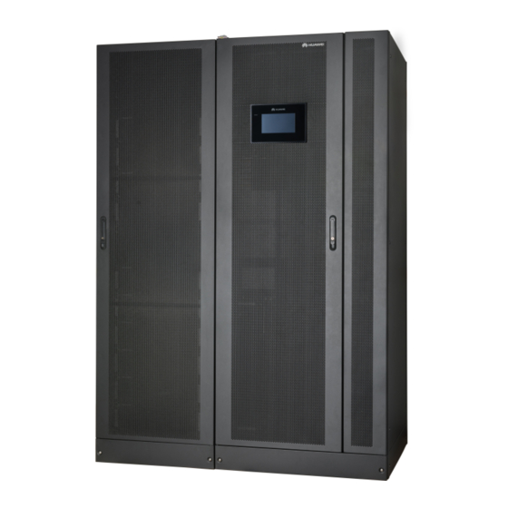
Manual startup is required to ensure that the inverter is in standby state and the power flow has reached the inverter. 2.3 Product Introduction 2.3.1 Appearance Figure 2-9 to Figure 2-11 show the 400 kVA, 500 kVA, 600 kVA, and 800 kVA UPSs. Issue 05 (2019-02-27) Copyright © Huawei Technologies Co., Ltd. - Page 30 UPS5000-S-(350 kVA-800 kVA) User Manual User Manual 2 Overview Figure 2-9 400 kVA/500 kVA UPS (1) Power (2) Anchor baffle (3) Monitor display unit (4) Bypass cabinet plates (MDU) cabinet Issue 05 (2019-02-27) Copyright © Huawei Technologies Co., Ltd.
- Page 31 UPS5000-S-(350 kVA-800 kVA) User Manual User Manual 2 Overview Figure 2-10 600 kVA UPS (1) Power cabinet (2) Anchor baffle plates (3) MDU (4) Bypass cabinet Issue 05 (2019-02-27) Copyright © Huawei Technologies Co., Ltd.
-
Page 32: Product Structure
(3) Anchor baffle plates (4) MDU (5) Bypass cabinet 2 (6) Bypass cabinet 1 2.3.2 Product Structure Figure 2-12 to Figure 2-19 show the structures of UPSs with the front doors open. Issue 05 (2019-02-27) Copyright © Huawei Technologies Co., Ltd. - Page 33 User Manual 2 Overview Figure 2-12 Product structure (400 kVA in standard configuration) (1) Power modules (2) Control module (3) Power distribution module cover (4) Maintenance bypass switch (5) Bypass module Issue 05 (2019-02-27) Copyright © Huawei Technologies Co., Ltd.
- Page 34 Figure 2-13 Product structure (400 kVA in full configuration) (1) Power modules (2) Control module (3) Power distribution module cover (4) Maintenance bypass (5) Bypass module (6) Mains input switch switch (7) Output switch (8) Bypass input switch Issue 05 (2019-02-27) Copyright © Huawei Technologies Co., Ltd.
- Page 35 User Manual 2 Overview Figure 2-14 Product structure (500 kVA in standard configuration) (1) Power modules (2) Control module (3) Power distribution module cover (4) Maintenance bypass switch (5) Bypass module Issue 05 (2019-02-27) Copyright © Huawei Technologies Co., Ltd.
- Page 36 Figure 2-15 Product structure (500 kVA in full configuration) (1) Power modules (2) Control module (3) Power distribution module cover (4) Maintenance bypass (5) Bypass module (6) Mains input switch switch (7) Output switch (8) Bypass input switch Issue 05 (2019-02-27) Copyright © Huawei Technologies Co., Ltd.
- Page 37 User Manual 2 Overview Figure 2-16 Product structure (600 kVA in standard configuration) (1) Power modules (2) Control module (3) Power distribution module cover (4) Maintenance bypass switch (5) Bypass module Issue 05 (2019-02-27) Copyright © Huawei Technologies Co., Ltd.
- Page 38 Figure 2-17 Product structure (600 kVA in full configuration) (1) Power modules (2) Control module (3) Power distribution module cover (4) Maintenance bypass (5) Bypass module (6) Mains input switch switch (7) Output switch (8) Bypass input switch Issue 05 (2019-02-27) Copyright © Huawei Technologies Co., Ltd.
- Page 39 Figure 2-19 Product structure (800 kVA in full configuration) (1) Power modules (2) Control module (3) Maintenance bypass switch (4) Power distribution module (5) Bypass module (6) Mains input switch cover Issue 05 (2019-02-27) Copyright © Huawei Technologies Co., Ltd.
-
Page 40: Power Module
The inverter is ready and in intervals standby state (blinking at 0.5 Hz, on for 1s and off for 1s). The inverter is not started (blinking at 0.2 Hz, on for 2.5s Issue 05 (2019-02-27) Copyright © Huawei Technologies Co., Ltd. -
Page 41: Bypass Module
Rated output capacity: 50 kVA/50 kW Power density: 50 kVA/3 U 2.3.4 Bypass Module Appearance 400 kVA/500 kVA/600 kVA bypass module have the same appearance. Figure 2-21 shows the 600 kVA bypass module. Issue 05 (2019-02-27) Copyright © Huawei Technologies Co., Ltd. - Page 42 Figure 2-22 shows the 800 kVA bypass module. Figure 2-22 800kVA bypass module (1) Positioning (2) Cold start (3) Run (4) Alarm indicator lock button indicator (5) Fault indicator (6) Ready switch (7) Crowbar (8) Auxiliary power supply Issue 05 (2019-02-27) Copyright © Huawei Technologies Co., Ltd.
- Page 43 400 kVA/500 kVA/600 kVA: 600 mm x 200 mm x 600 mm − 800 kVA: 500 mm x 480 mm x 550 mm Weight − 400 kVA/500 kVA/600 kVA: 50 kg Issue 05 (2019-02-27) Copyright © Huawei Technologies Co., Ltd.
-
Page 44: Control Module
(17) Battery temperature (18) Optional card sensor port subrack cover Ports are protected by a security mechanism. 2.3.5.2 ECM Appearance The control module consists of two energy control modules (ECMs) in active/standby mode. Issue 05 (2019-02-27) Copyright © Huawei Technologies Co., Ltd. - Page 45 The ECM has no minor alarm or the DSP of the ECM is being upgraded. FAULT Steady on The ECM has a critical alarm. The ECM has no critical alarm or the DSP of the ECM is being upgraded. Issue 05 (2019-02-27) Copyright © Huawei Technologies Co., Ltd.
-
Page 46: Dry Contact Card
CAN communication, and inter-rack parallel CAN communication. Figure 2-25 Logical connections for CAN communication Specifications Hot-swappable 1 U high 2.3.5.3 Dry contact card Appearance Figure 2-26 Dry contact card Issue 05 (2019-02-27) Copyright © Huawei Technologies Co., Ltd. - Page 47 STATUS_ output circuit breaker breaker ON Disconnected: circuit breaker SWITCH Port for signal ground STATUS_ SWITCH Port for monitoring the Disconnected: Disconnected STATUS_ maintenance circuit breaker circuit breaker ON Issue 05 (2019-02-27) Copyright © Huawei Technologies Co., Ltd.
-
Page 48: Monitoring Interface Card
The dry contact card allows the UPS to detect and manage the switch status of the battery system (including the external battery switch) and implement remote emergency power-off (EPO). Specifications Hot-swappable 0.5 U high 2.3.5.4 Monitoring interface card Issue 05 (2019-02-27) Copyright © Huawei Technologies Co., Ltd. - Page 49 DO_2 is used to output alarms and indicates minor alarms by default. It can be set to indicate critical alarms, bypass mode, battery mode, or low battery voltage. DO_3 DO_3 is used to output Issue 05 (2019-02-27) Copyright © Huawei Technologies Co., Ltd.
- Page 50 Signal cables must be double-insulated twisted cables. If the cable length is 25–50 m, the cross-sectional area must be 0.5–1.5 mm RS485 cables and FE cables must be shielded cables. Figure 2-28 and Figure 2-29 are recommended wiring methods for DO ports. Issue 05 (2019-02-27) Copyright © Huawei Technologies Co., Ltd.
- Page 51 UPS5000-S-(350 kVA-800 kVA) User Manual User Manual 2 Overview Figure 2-28 Wiring method 1 Figure 2-29 Wiring method 2 Figure 2-30 COM1 pins Table 2-8 COM1 pin definition Description RS485– RS485+ Issue 05 (2019-02-27) Copyright © Huawei Technologies Co., Ltd.
- Page 52 UPS5000-S-(350 kVA-800 kVA) User Manual User Manual 2 Overview Description 12V_PORT Figure 2-31 COM2 pins Table 2-9 COM2 pin definition Description RS485+ RS485– RS485+ RS485– CANH0 CANL0 Issue 05 (2019-02-27) Copyright © Huawei Technologies Co., Ltd.
- Page 53 Connect pins 1, 2, 4, and 5. Twist cables to pin 1 and pin 4 into one cable and then connect it to RS485+. Twist cables to pin 2 and pin 5 into one cable and then connect it to RS485–. Issue 05 (2019-02-27) Copyright © Huawei Technologies Co., Ltd.
-
Page 54: Mdu
Table 2-11 Status indicator Status Color Meaning A critical alarm has been generated, and the buzzer sounds continuously. Yellow A minor alarm has been generated, and the buzzer buzzes at 2 Hz. Issue 05 (2019-02-27) Copyright © Huawei Technologies Co., Ltd. - Page 55 Insert the USB flash drive, import and export the configuration file, export run logs, and upgrade software. Restart switch for the MDU Issue 05 (2019-02-27) Copyright © Huawei Technologies Co., Ltd.
-
Page 56: Typical Configurations
This series uses a modular design in which multiple power modules are connected in parallel to deliver a high loading capacity. If a single power module is faulty, the other power modules Issue 05 (2019-02-27) Copyright © Huawei Technologies Co., Ltd. -
Page 57: Parallel System
An optional static transfer switch (STS) can be installed to start the bus synchronization controller (BSC). The UPS systems work in normal mode or bypass mode. Issue 05 (2019-02-27) Copyright © Huawei Technologies Co., Ltd. -
Page 58: Optional Components
Converges the energy of kVA, multiple battery strings. PDU8000-2000DCV8-BGA kVA, 600 kVA 800 kVA PDU8000-2000DCV8-BGA001 Ensures heat dissipation. For air-flow details, see the document cabinet delivered with the top air-flow cabinet. Issue 05 (2019-02-27) Copyright © Huawei Technologies Co., Ltd. - Page 59 Parallel 5 m/10 m/15 m Connects UPSs in parallel. cable 5 m/10 m/15 m/60 m Transmits bus synchronization cable signals in a dual-bus system. Issue 05 (2019-02-27) Copyright © Huawei Technologies Co., Ltd.
- Page 60 If an IP21 component is installed, cables cannot be routed from the top of the cabinet. The ECM extended subrack does not support onsite installation. If this component is required, inform Huawei before purchasing the UPS to receive pre-installation services. Issue 05 (2019-02-27) Copyright © Huawei Technologies Co., Ltd.
-
Page 61: Installation
UPS5000-S-(350 kVA-800 kVA) User Manual User Manual 3 Installation Installation 3.1 Installation Preparations 3.1.1 Site 3.1.1.1 UPS Dimensions Figure 3-1 Dimensions (400 kVA/500 kVA, unit: mm) Issue 05 (2019-02-27) Copyright © Huawei Technologies Co., Ltd. - Page 62 UPS5000-S-(350 kVA-800 kVA) User Manual User Manual 3 Installation Figure 3-2 Dimensions (600 kVA, unit: mm) Issue 05 (2019-02-27) Copyright © Huawei Technologies Co., Ltd.
-
Page 63: Installation Environment
If a top air-flow cabinet is deployed, the UPS can be installed against a wall and no space needs to be reserved at the rear (except the 800 kVA UPS). If no top air-flow cabinet is Issue 05 (2019-02-27) Copyright © Huawei Technologies Co., Ltd. -
Page 64: Tools And Instruments
Insulate installation tools to prevent electric shocks. Prepare the following tools and meters indicated in Table 3-1 for installation. Table 3-1 Tools and meters Tools and Meters Electric pallet truck Manual pallet truck Ladder Rubber mallet Issue 05 (2019-02-27) Copyright © Huawei Technologies Co., Ltd. - Page 65 Level instrument Polyvinyl chloride Cotton cloth Label Electrician's knife (PVC) insulation tape Electrostatic Protective gloves Insulated gloves Insulation protective discharge (ESD) shoes gloves Torque screwdriver Cable cutter Brush Flat-head screwdriver (2–5 mm) Issue 05 (2019-02-27) Copyright © Huawei Technologies Co., Ltd.
-
Page 66: Power Cables
2 x (4 x 185) 2 x (4 x 240) 3 x (4 x 185) 3 x (4 x 185) 3 x (4 x 240) conn nded ector cross-secti onal area Issue 05 (2019-02-27) Copyright © Huawei Technologies Co., Ltd. - Page 67 4 x (4 x 185) 4 x (4 x 240) 4 x (4 x 240) 4 x (4 x 240) 4 x (4 x 240) conn nded ector cross-secti onal area Issue 05 (2019-02-27) Copyright © Huawei Technologies Co., Ltd.
- Page 68 The maximum battery discharge current refers to the current when forty 12 V batteries in standard configuration, that is, two hundred and forty 2 V battery cells (1.67 V/cell), stop discharging. Issue 05 (2019-02-27) Copyright © Huawei Technologies Co., Ltd.
- Page 69 47 N· m terminals connector Table 3-5 Recommended upstream input and downstream output circuit breakers UPS Capacity Component Specifications 350 kVA Mains input circuit breaker 800 A/3P Bypass input circuit breaker 630 A/3P Issue 05 (2019-02-27) Copyright © Huawei Technologies Co., Ltd.
- Page 70 Bypass input circuit breaker 1250 A/3P Output branch circuit 1250 A/3P breaker 750 kVA Mains input circuit breaker 1600 A/3P Bypass input circuit breaker 1250 A/3P Output branch circuit 1250 A/3P breaker Issue 05 (2019-02-27) Copyright © Huawei Technologies Co., Ltd.
-
Page 71: Unpacking
Step 1 Use a pallet truck to transport the UPS to the installation position. Step 2 Remove the UPS outer packing. Step 3 Remove the bolts that secure the UPS to the pallet and remove the UPS from the pallet. Issue 05 (2019-02-27) Copyright © Huawei Technologies Co., Ltd. -
Page 72: Optional) Splitting The Power Cabinet And Bypass Cabinet (400 Kva, 500 Kva, Or 600 Kva Ups)
Table 3-6 Specifications and number of screws (400 kVA or 500 kVA UPS) Position Screw Specification Quantity (PCS) Soft copper bar M12x35 Battery copper bar M8x20 component Top connecting plate M6x30 Middle connecting plate M6x30 Issue 05 (2019-02-27) Copyright © Huawei Technologies Co., Ltd. - Page 73 Step 1 Open the front door of the bypass cabinet and remove the covers of the power distribution subrack. The covers of the power distribution subrack can be removed from the bypass cabinet only when all switches are OFF. Issue 05 (2019-02-27) Copyright © Huawei Technologies Co., Ltd.
- Page 74 Step 3 Remove the cable terminals that connect the system signal interface board in the power cabinet to the bypass cabinet. Disconnect cables by referring to Figure 3-7 and Table 3-8, and cut off the cable ties on the disconnected cables. Issue 05 (2019-02-27) Copyright © Huawei Technologies Co., Ltd.
- Page 75 ECM system W307_J25 monitoring bus CT cable W309_J26 Switch cable SW1_J27 SW2_J28 SW4_J30 Because the switch extension rod is sharp, exercise caution when removing the connecting copper bars to prevent personal injury. Issue 05 (2019-02-27) Copyright © Huawei Technologies Co., Ltd.
- Page 76 Figure 3-8 Removing soft copper bars numbered 43, 44, and 45 For a 500 kVA or 600 kVA UPS, remove the soft copper bars numbered 56, 58, and 60. Step 5 Remove the battery copper bar component. Issue 05 (2019-02-27) Copyright © Huawei Technologies Co., Ltd.
- Page 77 UPS5000-S-(350 kVA-800 kVA) User Manual User Manual 3 Installation Figure 3-9 Removing the battery copper bar component Step 6 Remove the soft copper bars numbered 39–42. Issue 05 (2019-02-27) Copyright © Huawei Technologies Co., Ltd.
- Page 78 Step 7 Remove the top, middle, and bottom connecting plates in sequence from the power cabinet and bypass cabinet. Use a step ladder to remove the top connecting plates as the cabinet is high. Issue 05 (2019-02-27) Copyright © Huawei Technologies Co., Ltd.
-
Page 79: Optional) Combining The Power Cabinet And Bypass Cabinet (400 Kva, 500 Kva, Or 600 Kva Ups)
Step 4 Check that the power cabinet and bypass cabinet are combined completely and securely. Step 5 After checking that cabinets are combined properly, reinstall the side covers and rear covers. ----End Issue 05 (2019-02-27) Copyright © Huawei Technologies Co., Ltd. -
Page 80: Single Ups Installation
Step 1 Determine the cabinet installation positions on the ground based on holes in the marking-off template for ground installation. A: mounting holes on the channel steel B: mounting holes on the floor Issue 05 (2019-02-27) Copyright © Huawei Technologies Co., Ltd. - Page 81 Step 2 Use a hammer drill to drill holes for installing expansion bolts, and install expansion sleeves in the holes. Figure 3-15 shows expansion bolt composition. Figure 3-16 shows how to install an expansion bolt. Issue 05 (2019-02-27) Copyright © Huawei Technologies Co., Ltd.
- Page 82 Partially tighten the expansion bolt and vertically insert it into the hole. Knock the expansion bolt using a rubber mallet until the expansion sleeve is fully inserted into the hole. Partially tighten the expansion bolt. Remove the bolt, spring washer, and flat washer. Issue 05 (2019-02-27) Copyright © Huawei Technologies Co., Ltd.
- Page 83 Step 5 Install the front, rear, left, and right anchor baffle plates. The installation methods for different UPS models are the same. Figure 3-18 shows how to install anchor baffle plates for a 400 kVA UPS cabinet. Issue 05 (2019-02-27) Copyright © Huawei Technologies Co., Ltd.
- Page 84 Figure 3-20. Figure 3-19 Installing a lock for the maintenance bypass switch (400 kVA UPS, 500 kVA UPS) Figure 3-20 Installing a lock for the maintenance bypass switch (600 kVA UPS) ----End Issue 05 (2019-02-27) Copyright © Huawei Technologies Co., Ltd.
-
Page 85: Installing The Ups On Channel Steel
A: mounting holes on the channel steel B: mounting holes on the floor Figure 3-21 Mounting hole dimensions for the 400 kVA UPS and 500 kVA UPS (unit: mm) Issue 05 (2019-02-27) Copyright © Huawei Technologies Co., Ltd. -
Page 86: Installing A Ups (800 Kva)
Step 1 Determine the cabinet installation positions on the ground based on holes in the marking-off template for ground installation. A: mounting holes on the channel steel B: mounting holes on the floor Issue 05 (2019-02-27) Copyright © Huawei Technologies Co., Ltd. - Page 87 (4) Expansion sleeve Knock the expansion bolt into the hole until the expansion sleeve completely fits into the hole. The expansion sleeve must be completely buried under the ground to facilitate subsequent installation. Issue 05 (2019-02-27) Copyright © Huawei Technologies Co., Ltd.
- Page 88 52. Soft M12x45 If holes are drilled for connecting routing cables at the top copper bar of the cabinet, attach grommet strips on the Grommet hole edges to protect Issue 05 (2019-02-27) Copyright © Huawei Technologies Co., Ltd.
- Page 89 Figure 3-26 Installing connecting plates Step 4 Use M12x60 expansion bolts to secure the cabinets to the expansion bolt holes on the ground. Figure 3-27 shows how to secure the power cabinets. Issue 05 (2019-02-27) Copyright © Huawei Technologies Co., Ltd.
- Page 90 Step 6 Remove the front covers of the power distribution subrack from the bypass cabinets, as shown in Figure 3-29. The front covers of the power distribution subrack can be removed only when all the switches are OFF. Issue 05 (2019-02-27) Copyright © Huawei Technologies Co., Ltd.
- Page 91 When reinstalling the switch extension rod, keep the dowel level, as shown in Figure 3-30. Insert the switch extension rod to the blue mark, put washers, and tighten the slotted screw to reinstall the switch extension rod. Issue 05 (2019-02-27) Copyright © Huawei Technologies Co., Ltd.
- Page 92 Cut off the cable ties bound between holes in soft copper bars numbered 23, 24, 25, 26, and 30. Secure the soft copper bars numbered 23, 24, 25, 26, and 30 using M12x45 screws, as shown in Figure 3-31. Issue 05 (2019-02-27) Copyright © Huawei Technologies Co., Ltd.
- Page 93 Remove filler panels from power cabinet 1. Take out two soft copper bars numbered 52 from the fittings, and secure them to power cabinet 1 and its adjacent bypass cabinet respectively, as shown in Figure 3-32. Issue 05 (2019-02-27) Copyright © Huawei Technologies Co., Ltd.
- Page 94 Figure 3-33. The mapping between the cables in the bypass cabinets and the ports on the system signal interface board is listed in Table 3-10. Figure 3-34 shows cable connections for combined cabinets. Issue 05 (2019-02-27) Copyright © Huawei Technologies Co., Ltd.
- Page 95 (output switch, maintenance bypass switch, and bypass input switch). The following figure describes how to connect cables for combined cabinets using a full configuration model as an example. Issue 05 (2019-02-27) Copyright © Huawei Technologies Co., Ltd.
-
Page 96: Installing The Ups On Channel Steel
Step 1 Determine the cabinet installation positions on the channel steel based on holes in the marking-off template for channel steel installation. A: mounting holes on the channel steel B: mounting holes on the floor Issue 05 (2019-02-27) Copyright © Huawei Technologies Co., Ltd. -
Page 97: Installing Batteries
Step 1 Use common M12x45 bolts to secure the cabinets into the mounting holes in the channel steel and tighten the bolts. Step 2 Install the front, rear, left, and right anchor baffle plates. ----End 3.2.3 Installing Batteries Context Issue 05 (2019-02-27) Copyright © Huawei Technologies Co., Ltd. -
Page 98: Installing Optional Components
Install antiseismic kits only when the cabinet is ground-mounted. Step 1 Mark mounting holes on the ground based on the marking-off templates. Figure 3-36 to Figure 3-38 show the dimensions of antiseismic kit mounting holes. Issue 05 (2019-02-27) Copyright © Huawei Technologies Co., Ltd. - Page 99 UPS5000-S-(350 kVA-800 kVA) User Manual User Manual 3 Installation Figure 3-36 Dimensions of antiseismic kit mounting holes for the 400 kVA UPS and 500 kVA UPS (unit: mm) Issue 05 (2019-02-27) Copyright © Huawei Technologies Co., Ltd.
- Page 100 3 Installation Figure 3-37 Dimensions of antiseismic kit mounting holes for the 600 kVA UPS (unit: mm) Figure 3-38 Dimensions of antiseismic kit mounting holes for the 800 kVA UPS (unit: mm) Issue 05 (2019-02-27) Copyright © Huawei Technologies Co., Ltd.
- Page 101 Step 6 Use expansion bolts to firmly lock the front and rear antiseismic kits to the ground. The installation methods for different UPS models are the same. Figure 3-41 shows how to lock antiseismic kits for a 600 kVA UPS. Issue 05 (2019-02-27) Copyright © Huawei Technologies Co., Ltd.
-
Page 102: Installing An Ip21 Component
Select the mounting holes for leveling feet based on the cabinet width onsite. Figure 3-42 Installing leveling feet Step 2 Secure the IP21 component to the top of each cabinet using four M12 screws. Issue 05 (2019-02-27) Copyright © Huawei Technologies Co., Ltd. -
Page 103: Connecting An Ambient T/H Sensor
Step 1 Connect the RJ11 port on the ambient T/H sensor to the COM1 port on the monitoring interface card. Figure 3-44 Connecting a UPS and an ambient T/H sensor The ambient T/H sensor can be used as a battery temperature sensor. ----End Issue 05 (2019-02-27) Copyright © Huawei Technologies Co., Ltd. -
Page 104: Connecting The Bcb Box
Box User Manual. 3.2.4.6 Installing a Battery Grounding Failure Detector Procedure Step 1 Install a battery grounding failure detector. For the installation method, see UPS Battery Grounding Failure Detector User Manual. Issue 05 (2019-02-27) Copyright © Huawei Technologies Co., Ltd. - Page 105 UPS5000-S-(350 kVA-800 kVA) User Manual User Manual 3 Installation Figure 3-45 Position of a battery grounding failure detector in the 400 kVA, 500 kVA, or 600 kVA (1) Battery grounding failure detector Issue 05 (2019-02-27) Copyright © Huawei Technologies Co., Ltd.
-
Page 106: Connecting The Ibat
(1) Battery grounding failure detector ----End 3.2.4.7 Connecting the iBAT Procedure Step 1 Connect the COM_OUT port on the CIM of the iBAT to the COM2 port on the monitoring interface card. Issue 05 (2019-02-27) Copyright © Huawei Technologies Co., Ltd. -
Page 107: Ups Cable Connection Reference
Step 3 Pull the marked cable out of the cabinet, cut the cable from the marked position, strip the cable, and crimp a terminal. Issue 05 (2019-02-27) Copyright © Huawei Technologies Co., Ltd. -
Page 108: Routing Cables (400 Kva, 500 Kva, Or 600 Kva Ups)
Step 4 Connect the cable with a crimped terminal to the corresponding copper bar. Step 5 Clean foreign matter inside the cabinet. ----End 3.2.6 Routing Cables (400 kVA, 500 kVA, or 600 kVA UPS) Issue 05 (2019-02-27) Copyright © Huawei Technologies Co., Ltd. -
Page 109: Top Cable Routing
3.2.6.1 Top Cable Routing Context Figure 3-49 Power distribution module (400 kVA UPS, 500 kVA UPS) (1) Mains input (2) Battery input (3) Output terminal (4) Bypass input terminal terminal terminal Issue 05 (2019-02-27) Copyright © Huawei Technologies Co., Ltd. - Page 110 (4) Bypass input terminal terminal terminal Procedure Step 1 Open the front door of the bypass cabinet and remove the covers of the power distribution subrack, as shown in Figure 3-51. Issue 05 (2019-02-27) Copyright © Huawei Technologies Co., Ltd.
- Page 111 Step 2 Remove the covers from the top of the cabinet, drill holes in the covers for the power cables and battery cables, attach grommet strips to the hole edges for protecting cables, and reinstall the covers. The hole diameter and quantity are for reference only. Issue 05 (2019-02-27) Copyright © Huawei Technologies Co., Ltd.
- Page 112 (Optional) If copper bar protective covers are installed for the bypass cabinet, remove the protective covers and then the connecting copper bars. The protective covers need to be reinstalled after the connecting copper bars are removed. Issue 05 (2019-02-27) Copyright © Huawei Technologies Co., Ltd.
- Page 113 UPS5000-S-(350 kVA-800 kVA) User Manual User Manual 3 Installation Figure 3-53 Removing the copper bar protective covers at the rear Issue 05 (2019-02-27) Copyright © Huawei Technologies Co., Ltd.
- Page 114 Figure 3-54 Removing the connecting copper bars Step 5 Connect a ground cable to the UPS. If you do not ground the UPS as required, electromagnetic interference, electric shocks, or fire may occur. Issue 05 (2019-02-27) Copyright © Huawei Technologies Co., Ltd.
- Page 115 Connect input power cables to the UPS and then to customer equipment. Figure 3-55 Ground cable Step 6 Connect the mains input power cables. Issue 05 (2019-02-27) Copyright © Huawei Technologies Co., Ltd.
- Page 116 Figure 3-56 Connecting the mains input power cables Step 7 Connect the output power cables. After you connect output power cables, if loads are not ready to be powered, insulate the end of the system output power cable. Issue 05 (2019-02-27) Copyright © Huawei Technologies Co., Ltd.
- Page 117 3 Installation Figure 3-57 Connecting AC output power cables Step 8 Connect the bypass input power cables. (Perform this step only when the mains input and bypass input use different power sources.) Issue 05 (2019-02-27) Copyright © Huawei Technologies Co., Ltd.
- Page 118 UPS5000-S-(350 kVA-800 kVA) User Manual User Manual 3 Installation Figure 3-58 Connecting the bypass input power cables Step 9 Connect the battery cables. Issue 05 (2019-02-27) Copyright © Huawei Technologies Co., Ltd.
- Page 119 Figure 3-59 Connecting battery cables Step 10 Route signal cables. Bind cables to the cabinet. Figure 3-60 shows the signal cables routed from the top of the cabinet. Bind signal cables and power cables separately. Issue 05 (2019-02-27) Copyright © Huawei Technologies Co., Ltd.
-
Page 120: Bottom Cable Routing
After connecting cables, check that a certain clearance is reserved between the internal switch (if any) extension pole and power cables to avoid friction. 3.2.6.2 Bottom Cable Routing Context Issue 05 (2019-02-27) Copyright © Huawei Technologies Co., Ltd. - Page 121 The hole size and quantity are for reference only. Figure 3-61 Removing the bottom cable covers and drilling holes (1) Power cable covers (2) Signal cable hole Issue 05 (2019-02-27) Copyright © Huawei Technologies Co., Ltd.
- Page 122 Step 5 Connect a ground cable to the UPS. If you do not ground the UPS as required, electromagnetic interference, electric shocks, or fire may occur. Issue 05 (2019-02-27) Copyright © Huawei Technologies Co., Ltd.
- Page 123 Connect the input power cables to the UPS before connecting power cables to customer equipment. Figure 3-62 Grounding Step 6 Connect the bypass input power cables. (Perform this step only when the mains input and bypass input use different power sources.) Issue 05 (2019-02-27) Copyright © Huawei Technologies Co., Ltd.
- Page 124 Figure 3-63 Connecting the bypass input power cables Step 7 Connect the output power cables. After connecting the output power cables, if loads are not ready to be powered, insulate the terminals of the output power cables. Issue 05 (2019-02-27) Copyright © Huawei Technologies Co., Ltd.
- Page 125 UPS5000-S-(350 kVA-800 kVA) User Manual User Manual 3 Installation Figure 3-64 Connecting output power cables Step 8 Connect the mains input power cables. Issue 05 (2019-02-27) Copyright © Huawei Technologies Co., Ltd.
- Page 126 UPS5000-S-(350 kVA-800 kVA) User Manual User Manual 3 Installation Figure 3-65 Connecting the mains input power cables Step 9 Connect the battery cables. Issue 05 (2019-02-27) Copyright © Huawei Technologies Co., Ltd.
- Page 127 UPS. Avoid inverse connections. Figure 3-66 Connecting battery cables Step 10 Route signal cables. Bind cables to the cabinet. Figure 3-67 shows the signal cables routed from the bottom of the cabinet. Issue 05 (2019-02-27) Copyright © Huawei Technologies Co., Ltd.
-
Page 128: Routing Cables (800 Kva Ups)
After connecting cables, check that a certain clearance is reserved between the internal switch (if any) extension pole and power cables to avoid friction. 3.2.7 Routing Cables (800 kVA UPS) Issue 05 (2019-02-27) Copyright © Huawei Technologies Co., Ltd. -
Page 129: Top Cable Routing
Figure 3-68 Power distribution module (1) Battery input (2) Mains input (3) Output terminal (4) Bypass input terminal terminal terminal Issue 05 (2019-02-27) Copyright © Huawei Technologies Co., Ltd. - Page 130 Step 4 Remove the copper bars between the mains and bypass inputs. (Perform this step only when the mains input and bypass input use different power sources.) Properly keep the removed copper bars and bolts. Issue 05 (2019-02-27) Copyright © Huawei Technologies Co., Ltd.
- Page 131 The protective covers need to be reinstalled after the connecting copper bars are removed. Figure 3-70 Removing the connecting copper bars Step 5 Connect a ground cable to the UPS. Issue 05 (2019-02-27) Copyright © Huawei Technologies Co., Ltd.
- Page 132 Connect the input power cables to the UPS before connecting power cables to customer equipment. Figure 3-71 Grounding Step 6 Connect the mains input power cables. Issue 05 (2019-02-27) Copyright © Huawei Technologies Co., Ltd.
- Page 133 Figure 3-72 Connecting the mains input power cables Step 7 Connect the output power cables. After connecting the output power cables, if loads are not ready to be powered, insulate the terminals of the output power cables. Issue 05 (2019-02-27) Copyright © Huawei Technologies Co., Ltd.
- Page 134 Step 8 Connect the bypass input power cables. (Perform this step only when the mains input and bypass input use different power sources.) Figure 3-74 Connecting the bypass input power cables Issue 05 (2019-02-27) Copyright © Huawei Technologies Co., Ltd.
- Page 135 Step 10 Route signal cables. Bind cables to the cabinet. Figure 3-76 shows the signal cables routed from the top of the cabinet. Do not bind signal cables and power cables together. Issue 05 (2019-02-27) Copyright © Huawei Technologies Co., Ltd.
-
Page 136: Bottom Cable Routing
Step 2 Remove the cable covers from the bottom of the cabinet, drill holes in the covers, attach grommet strips to the hole edges for protecting cables, and reinstall the cable covers. The hole diameter and quantity are for reference only. Issue 05 (2019-02-27) Copyright © Huawei Technologies Co., Ltd. - Page 137 Step 5 Connect a ground cable to the UPS. If you do not ground the UPS as required, electromagnetic interference, electric shocks, or fire may occur. Issue 05 (2019-02-27) Copyright © Huawei Technologies Co., Ltd.
- Page 138 Connect the input power cables to the UPS before connecting power cables to customer equipment. Figure 3-78 Grounding Step 6 Connect the bypass input power cables. (Perform this step only when the mains input and bypass input use different power sources.) Issue 05 (2019-02-27) Copyright © Huawei Technologies Co., Ltd.
- Page 139 Figure 3-79 Connecting the bypass input power cables Step 7 Connect the output power cables. After connecting the output power cables, if loads are not ready to be powered, insulate the terminals of the output power cables. Issue 05 (2019-02-27) Copyright © Huawei Technologies Co., Ltd.
- Page 140 UPS5000-S-(350 kVA-800 kVA) User Manual User Manual 3 Installation Figure 3-80 Connecting the output power cables Step 8 Connect the mains input power cables. Issue 05 (2019-02-27) Copyright © Huawei Technologies Co., Ltd.
- Page 141 UPS5000-S-(350 kVA-800 kVA) User Manual User Manual 3 Installation Figure 3-81 Connecting the mains input power cables Step 9 Connect the battery cables. Issue 05 (2019-02-27) Copyright © Huawei Technologies Co., Ltd.
- Page 142 Step 10 Route signal cables. Bind cables to the cabinet. Figure 3-83 shows the signal cables routed from the bottom of the cabinet. Do not bind signal cables and power cables together. Issue 05 (2019-02-27) Copyright © Huawei Technologies Co., Ltd.
-
Page 143: Remote Epo
(if any) extension pole and power cables to avoid friction. 3.2.8 Remote EPO Huawei does not provide the EPO switch or cable. If the cable is required, the recommended cable is 22 AWG. Equip the EPO switch with a protective cover to prevent misoperations, and cover the cable with protective tubing. -
Page 144: Connecting Communications Cables
Step 1 Connect the external network management device to the RS485 port. Step 2 Connect the network port on a PC to the FE port of the monitoring interface card. ----End Issue 05 (2019-02-27) Copyright © Huawei Technologies Co., Ltd. -
Page 145: Parallel System Installation
Figure 3-86, Figure 3-87, and Figure 3-88 show the typical conceptual diagram and cable connections for a 1+1 parallel system. Figure 3-86 Conceptual diagram of a 1+1 parallel system Connect power cables according to port silk screen. Issue 05 (2019-02-27) Copyright © Huawei Technologies Co., Ltd. - Page 146 3 Installation Figure 3-87 Cable connections for a 1+1 parallel system (400 kVA UPS) (1) Mains input power (2) Bypass input power (3) Battery (4) Output power cables cables cables cables Issue 05 (2019-02-27) Copyright © Huawei Technologies Co., Ltd.
- Page 147 The length and specifications of power cables on each UPS must be the same to achieve current equalization in bypass mode. The power cables include bypass input power cables and UPS output power cables. Issue 05 (2019-02-27) Copyright © Huawei Technologies Co., Ltd.
- Page 148 UPS5000-S-(350 kVA-800 kVA) User Manual User Manual 3 Installation Figure 3-89 Conceptual diagram of a dual-bus system Issue 05 (2019-02-27) Copyright © Huawei Technologies Co., Ltd.
- Page 149 3 Installation Figure 3-90 Cable connections for a dual-bus parallel system (400 kVA UPS) (1) Mains input power (2) Bypass input power (3) Battery (4) Output power cables cables cables cables Issue 05 (2019-02-27) Copyright © Huawei Technologies Co., Ltd.
-
Page 150: Connecting Signal Cables
Connecting Signal Cables to a Parallel System Connect the parallel ports on the UPSs over parallel cables to create a loop. Figure 3-92 and Figure 3-93 show the wiring principle for an N+X parallel system. Issue 05 (2019-02-27) Copyright © Huawei Technologies Co., Ltd. - Page 151 Figure 3-93 Signal cable connections of N+X parallel system BSC master and slave cables are required in a dual-bus parallel system. Figure 3-94 shows the cable connections for a dual-bus system containing two master systems. Issue 05 (2019-02-27) Copyright © Huawei Technologies Co., Ltd.
-
Page 152: Installation Verification
3.4 Installation Verification Table 3-11 lists check items. If the check results of listed items 8 and 9 in Table 3-11 do not meet the acceptance criteria, the UPS may be damaged. Issue 05 (2019-02-27) Copyright © Huawei Technologies Co., Ltd. - Page 153 3. There is no foreign matter around switch terminals. 4. There is no foreign matter on the bottom plate of the cabinet. 5. There is no foreign matter on the rear module subrack. Issue 05 (2019-02-27) Copyright © Huawei Technologies Co., Ltd.
- Page 154 Figure 3-95 Positions to be checked for foreign matter (400 kVA) (1) Switches (2) Mains input wiring copper (3) Battery input wiring copper bar (4) Output wiring copper (5) Bypass input wiring (6) Rear of modules copper bar Issue 05 (2019-02-27) Copyright © Huawei Technologies Co., Ltd.
- Page 155 (1) Wiring terminal block (2) Cabinet top (3) Switches (4) Cabinet bottom (5) Rear of modules Figure 3-97 Fill the holes with sealing putty (1) Paper protective film (2) Sealing putty Issue 05 (2019-02-27) Copyright © Huawei Technologies Co., Ltd.
- Page 156 UPS5000-S-(350 kVA-800 kVA) User Manual User Manual 3 Installation Figure 3-98 Dustproof cover Issue 05 (2019-02-27) Copyright © Huawei Technologies Co., Ltd.
-
Page 157: User Interface
4-1 numerically labels functions of the default main screen, and Table 4-1 describes these functions. Figure 4-1 Main Menu screen Table 4-1 Main screen description Number Area Function Status bar Displays the UPS model, capacity, configuration, current date Issue 05 (2019-02-27) Copyright © Huawei Technologies Co., Ltd. -
Page 158: System Info Screen
Logs a user out. 4.1.2 System Info Screen On the main screen, tap System Info. The System Info screen is displayed, as shown in Figure 4-2. Figure 4-2 System Info screen Issue 05 (2019-02-27) Copyright © Huawei Technologies Co., Ltd. -
Page 159: Module Data Screen
Figure 4-3. Figure 4-3 Module Data screen 4.1.2.2 Running On the System Info screen, tap to access the Runn Info screen. Figure 4-4 Running 1 Issue 05 (2019-02-27) Copyright © Huawei Technologies Co., Ltd. - Page 160 Load ratio of each phase on the UPS, that is, proportion of actual power to rated power. Crest factor Proportion of the peak value of load current to the valid value. Issue 05 (2019-02-27) Copyright © Huawei Technologies Co., Ltd.
- Page 161 Battery operating temperature (A battery sensor is required. If the sensor is not installed, NA is displayed). Backup time (min) Battery backup time estimated at the current load. Remaining cap. (%) Remaining battery capacity. State of health. Issue 05 (2019-02-27) Copyright © Huawei Technologies Co., Ltd.
-
Page 162: Alarms Screen
Battery Detailed Data - String N Battery Data: reflects the temperature, voltage, internal resistance, current, SOC, and SOH data of a single battery in the battery string. 4.1.2.3 Alarms Screen on the System Info screen to enter the Alarms screen. Issue 05 (2019-02-27) Copyright © Huawei Technologies Co., Ltd. - Page 163 This screen displays alarm information including the severity, name, ID, location, and generation time. Figure 4-7 Active alarms Historical alarms This screen displays alarm information including the severity, name, ID, location, generation time, and clear time. Issue 05 (2019-02-27) Copyright © Huawei Technologies Co., Ltd.
-
Page 164: Settings
If this selection is enabled, the buzzer is muted. If the buzzer is enabled, Buzzer Off is displayed on the operation screen. 4.1.2.4 Settings On the System Info screen, tap to access the Settings screen. Figure 4-9 Settings 1 Issue 05 (2019-02-27) Copyright © Huawei Technologies Co., Ltd. - Page 165 UPS5000-S-(350 kVA-800 kVA) User Manual User Manual 4 User Interface Figure 4-10 Settings 2 Communication Settings Figure 4-11 Communication settings 1 Figure 4-12 Communication settings 2 Issue 05 (2019-02-27) Copyright © Huawei Technologies Co., Ltd.
- Page 166 Ensure that the MDU and PC are on the same network segment. After you restart the device, IP address allocation changes back to Manual. The IP address is set to the IP address set previously. Issue 05 (2019-02-27) Copyright © Huawei Technologies Co., Ltd.
- Page 167 Select a baud rate to match the 9600 9600, 19200, 115200 user's network management conditions onsite. Parity mode Verify the validity of RS485 None None, Odd, communication characters. When Even a device node adopts RS485 Issue 05 (2019-02-27) Copyright © Huawei Technologies Co., Ltd.
- Page 168 Default Value Value Range ModbusTCP If Modbus TCP is used for Enable Disable, Enable encryption communication, communication links do not implement encryption or implement encryption based on the selected encryption mode. Issue 05 (2019-02-27) Copyright © Huawei Technologies Co., Ltd.
- Page 169 Number of cascaded ambient 0–4 temperature and humidity sensors Figure 4-17 Battery temperature sensor Item Description Default Value Value Range Start address 16–28 Quantity Number of cascaded battery 0–4 temperature sensors Issue 05 (2019-02-27) Copyright © Huawei Technologies Co., Ltd.
- Page 170 SSID after connecting a WiFi characters of the module over a USB port to MAC address identify the WiFi device to which the mobile phone is connected. Password The password for accessing Changeme WiFi. Issue 05 (2019-02-27) Copyright © Huawei Technologies Co., Ltd.
- Page 171 UPS5000-S-(350 kVA-800 kVA) User Manual User Manual 4 User Interface System Settings Figure 4-20 System settings 1 Figure 4-21 System settings 2 Figure 4-22 System settings 3 Item Description Default Value Value Range Issue 05 (2019-02-27) Copyright © Huawei Technologies Co., Ltd.
- Page 172 BSC-related hardware is properly installed. ≤ 1000 ≤ 1000, Altitude (m) Set this parameter based on the altitude of the place where the 1000–2000, rack is used. 2000–3000, 3000–4000, 4000–5000 Issue 05 (2019-02-27) Copyright © Huawei Technologies Co., Ltd.
- Page 173 BCB trips if Indicates whether the BCB trips Enable Disable, Enable UPS stops when the system stops supplying power supply power and the output power is off. Issue 05 (2019-02-27) Copyright © Huawei Technologies Co., Ltd.
- Page 174 Input cur. Specifies whether to enable or Disable Disable, Enable limiting disable input current limiting to protect generators. Input cur. Limits the input current to protect 200% 50%–200% limiting ratio the D.G. Issue 05 (2019-02-27) Copyright © Huawei Technologies Co., Ltd.
- Page 175 If (Hz/s) Output freq. track rate (Hz/s) is slow, the inverter frequency is different from the bypass frequency when the bypass frequency changes. If output is overloaded or the inverter is Issue 05 (2019-02-27) Copyright © Huawei Technologies Co., Ltd.
- Page 176 Bypass When the difference between the ± 2 Hz ± 0.5 Hz to ± 6 frequency bypass input frequency and the Issue 05 (2019-02-27) Copyright © Huawei Technologies Co., Ltd.
- Page 177 2 V. A battery is a module consisting of single or multiple cells in a shell. Each battery has a nominal voltage of 2 V, 6 V, or 12 V. Figure 4-26 Battery settings 1 Issue 05 (2019-02-27) Copyright © Huawei Technologies Co., Ltd.
- Page 178 Number of Specifies the number of battery 1–4 battery strings strings connected in parallel. Installation A battery maintenance reminder time is displayed when the Issue 05 (2019-02-27) Copyright © Huawei Technologies Co., Ltd.
- Page 179 Shallow dis. Set the proportion of the 10%–50% test dis. ratio discharge capacity to the total discharge capacity. The value is configurable in any mode. Issue 05 (2019-02-27) Copyright © Huawei Technologies Co., Ltd.
- Page 180 Specifies the number of iBATs 0–300 of iBATs managed by the iBOX. iBOX logical Specifies the communication 0–124 start addr address when the northbound device queries iBOX data. Issue 05 (2019-02-27) Copyright © Huawei Technologies Co., Ltd.
- Page 181 Multi-Hall cur. setting is equal 1–8 setting to the number of Hall effect sensors at the positive or negative terminal of a battery string (Multi-Hall cur. setting ≥ 1). Figure 4-32 Batt. String Config Issue 05 (2019-02-27) Copyright © Huawei Technologies Co., Ltd.
- Page 182 If the BP/SYSMT switch is set to Enable, this parameter is displayed on the screen. Set this parameter to determine whether the port is used to detect the status of the PDU bypass input switch, or Issue 05 (2019-02-27) Copyright © Huawei Technologies Co., Ltd.
- Page 183 DO_2, MUE07A DO_3, on the MUE07A. MUE07A DO_4, MUE07A DO_5 MUE07A DI_1, MUE07A DI_2, Corresponds to the signal of the input dry contact DI MUE07A DI_3, MUE07A DI_4, on the MUE07A. MUE07A DI_5 Issue 05 (2019-02-27) Copyright © Huawei Technologies Co., Ltd.
- Page 184 If the password complexity check Enable Disable, Enable complexity is disabled, the user password is check required to be a string of six to eight digits. If the password complexity check is enabled, the Issue 05 (2019-02-27) Copyright © Huawei Technologies Co., Ltd.
-
Page 185: Maintenance
Choose Monitoring > Param. Settings > System Settings on the WebUI, if the Bus capa. life is set to Enable, the Maintenance is displayed on the Bus Capa. Life screen. Issue 05 (2019-02-27) Copyright © Huawei Technologies Co., Ltd. - Page 186 Capacity Test Fully discharge batteries. A deep discharge test is conducted to obtain the battery discharge performance data. Issue 05 (2019-02-27) Copyright © Huawei Technologies Co., Ltd.
- Page 187 Item Description Inv. ON The Inv. ON screen allows you to start the inverter manually. Inv. OFF The Inv. OFF screen allows you to shut down the inverter manually. ECM Switchover Issue 05 (2019-02-27) Copyright © Huawei Technologies Co., Ltd.
-
Page 188: About Screen
Bus capacitor life forecast If the service life of a capacitor is about to end, that is, Module X bus capacitor life (y) is less than 1.0, contact Huawei technical support to replace the power module. 4.1.2.6 About Screen On the System Info screen, tap About to view the UPS model, manufacturer name, monitoring version and power version, as shown in Figure 4-40. -
Page 189: Main Menu
Figure 4-41 Main Menu screen Table 4-11 Main screen description Number Area Function Status bar Displays the UPS model, capacity, configuration, current date and time, USB flash drive status, and buzzer status. Issue 05 (2019-02-27) Copyright © Huawei Technologies Co., Ltd. -
Page 190: System Status
Returns to the upper-level menu. Logs a user out. 4.1.4 System Status On the System Status to view the mains input, bypass input, load, and battery information. Figure 4-42 System status Issue 05 (2019-02-27) Copyright © Huawei Technologies Co., Ltd. -
Page 191: Common Functions
Step 1 Open the browser and choose Tools > Internet Options. Step 2 On the Advanced tab page, ensure that Use TLS 1.0, and Use TLS 1.1 are selected and click Issue 05 (2019-02-27) Copyright © Huawei Technologies Co., Ltd. - Page 192 Only browses the system running information. (browsing user) If an incorrect password is entered three consecutive times, the account will be logged out for 5 minutes. Issue 05 (2019-02-27) Copyright © Huawei Technologies Co., Ltd.
-
Page 193: Monitoring
Displays the power flow and UPS running information. area Menu bar Displays alarms and real-time data, sets parameters, and provides control commands. The Active Alarms page is displayed by default. Information Displays system monitoring information. area Issue 05 (2019-02-27) Copyright © Huawei Technologies Co., Ltd. -
Page 194: Parameter Settings
Module cycle Indicates the rotation interval of 1–100 hiber. period modules in hibernation mode. The default value is 30, which means that the hibernating module is rotated every 30 days. Issue 05 (2019-02-27) Copyright © Huawei Technologies Co., Ltd. - Page 195 BCB will trip in case of EOD. Input Settings Item Description Default Value Value Range Input The value of Input adaptability Strong Strong, Weak adaptability can be Strong or Weak. Strong Issue 05 (2019-02-27) Copyright © Huawei Technologies Co., Ltd.
- Page 196 Mod. Cur. Eql. Data can be viewed on the running information screen. Inverter async. Specifies whether an Inverter Disable Disable, Enable alarm asynchronous alarm can be displayed on the LCD when the Issue 05 (2019-02-27) Copyright © Huawei Technologies Co., Ltd.
- Page 197 Capacitor failure detection lower limit. If the power module determines that the inverter capacitor is faulty, it shuts down the inverter to prevent the fault from expanding. Issue 05 (2019-02-27) Copyright © Huawei Technologies Co., Ltd.
- Page 198 If this parameter is set to Enable, Enable Disable, Enable temp. comp. the float voltage is calibrated based on the battery temperature when a battery temperature sensor is connected. The parameter is configurable in any mode. Issue 05 (2019-02-27) Copyright © Huawei Technologies Co., Ltd.
- Page 199 Max. batt. dis. Set the maximum battery 0–48 time (h) discharge time. When the discharge time reaches this value, the UPS powers off. The battery discharge time can be set only to Issue 05 (2019-02-27) Copyright © Huawei Technologies Co., Ltd.
- Page 200 The calculation formula is (Charge/Discharge voltage – Average voltage)/Average voltage x 100%. Batt. charging After this function is enabled, an Disable Disable, Enable capacity alarm is generated if the mismatch configured battery capacity Issue 05 (2019-02-27) Copyright © Huawei Technologies Co., Ltd.
-
Page 201: Communication Settings
Batt. Volt. Below Threshold, dry contact and the battery voltage is lower (V/cell) than this threshold, the output dry contact will output signals. 4.2.2.2 Communication Settings Figure 4-48 Communication settings Issue 05 (2019-02-27) Copyright © Huawei Technologies Co., Ltd. -
Page 202: Control
On the Logs page, you can set Log to Historical logs, Cap. test logs, or Common test logs, and query or export logs. Historical logs can be exported but not queried. Issue 05 (2019-02-27) Copyright © Huawei Technologies Co., Ltd. -
Page 203: Config
If the password complexity check is enabled, the user password is required to be a string of 6–20 characters and contain at least two types of characters. 4.2.4.2 Site Config. On the home page, choose Config. > Site Config. Issue 05 (2019-02-27) Copyright © Huawei Technologies Co., Ltd. - Page 204 Configure Alarm Notification Email Address is used to configure the email address for receiving alarm emails from the monitoring system. ModbusTCP Certificate Management: ModbusTCP supports the Transport Layer Security (TLS) secure protocol for encrypted transmission and implements access Issue 05 (2019-02-27) Copyright © Huawei Technologies Co., Ltd.
-
Page 205: Rccmd
Enable upon first login. After you submit the setting, the page refreshes. The controls such as SSL Encrypted Transmission and Event Configuration will be displayed on the page, as shown in Figure 4-55. Figure 4-54 RCCMD function disabled Issue 05 (2019-02-27) Copyright © Huawei Technologies Co., Ltd. - Page 206 Disable, the RCCMD certificate controls will not be displayed on the page, as shown in Figure 4-57. If SSL Encrypted Transmission is set to Disable, a message indicating there is a risk will be displayed. Issue 05 (2019-02-27) Copyright © Huawei Technologies Co., Ltd.
- Page 207 The MDU supports 17 alarm events, and a maximum of 50 jobs can be added for each event, as shown in Figure 4-58. Figure 4-58 shows the buttons on the Event Configuration page, and Table 4-15 describes these buttons. Issue 05 (2019-02-27) Copyright © Huawei Technologies Co., Ltd.
- Page 208 Button for deleting all jobs You can delete all jobs of the event by clicking this button. Figure 4-59 shows the buttons after one event is expanded and Table 4-16 describes these buttons. Issue 05 (2019-02-27) Copyright © Huawei Technologies Co., Ltd.
- Page 209 When adding a job, the job types to be selected are: RCCMD Shutdown, RCCMD Message, RCCMD Execute, and RCCMD TRAP. RCCMD Shutdown is selected by default. For different job types, you need to enter different contents. Issue 05 (2019-02-27) Copyright © Huawei Technologies Co., Ltd.
- Page 210 RCCMD Message: Specify the RCCMD client IP address, port, and message to be conveyed. The RCCMD client will receive the message. For example, enter "This is a test message". Figure 4-61 RCCMD message Issue 05 (2019-02-27) Copyright © Huawei Technologies Co., Ltd.
- Page 211 UPS input voltage value (for example, single-phase: 220 V; three-phase A: 220 V, B: 220 V, C: 220 V). Table 4-17 lists the signal names that can be entered. Issue 05 (2019-02-27) Copyright © Huawei Technologies Co., Ltd.
- Page 212 #AUTONOMTIME Battery backup time minutes #STATUS UPS status #RUNTIME UPS operating time minutes #BATTVOLT Battery voltage #INFREQ Input frequency #BYPASSINFREQ Bypass input frequency #OUTFREQ Output frequency #CNT_PF Power supply failure times Issue 05 (2019-02-27) Copyright © Huawei Technologies Co., Ltd.
- Page 213 After the certificate is uploaded successfully, click Submit. The WebUI of the MDU will restart, and the uploaded certificate will be used for communication. Issue 05 (2019-02-27) Copyright © Huawei Technologies Co., Ltd.
-
Page 214: Managing The Ups By Using The Nms Complying With Rfc1628 Standard
MIB file which allows the third-party NMS to manage the UPS remotely. Figure 4-65 Download the MIB The UPS-RFC1628-MIB has more alarms than RFC1628. Download the UPS-RFC1628-MIB before using. Issue 05 (2019-02-27) Copyright © Huawei Technologies Co., Ltd. -
Page 215: Protecting The Server By Using The Rccmd Software
Configures and saves the address and port for receiving the shutdown command, and the message sending mechanism. For the method of installing the RCCMD client, see the manual related to the RCCMD. Issue 05 (2019-02-27) Copyright © Huawei Technologies Co., Ltd. -
Page 216: Rccmd Event Shutdown And Message Sending
Step 5 On the Monitoring > Control page, start the UPS, and the inverter mode will be triggered. Send the message to the RCCMD client, indicating that the inverter is on. Issue 05 (2019-02-27) Copyright © Huawei Technologies Co., Ltd. -
Page 217: Ups Alive Check Function
CS121/UPSMAN Traps. If by polling CS121/UPSMAN every x seconds... is selected as the method of detecting heartbeats, set the detection method. The default interval is 1800s and detection is performed 100 times, as shown in Figure 4-68. Issue 05 (2019-02-27) Copyright © Huawei Technologies Co., Ltd. - Page 218 UPS5000-S-(350 kVA-800 kVA) User Manual User Manual 4 User Interface Figure 4-68 Heartbeat detecting mode on the RCCMD client You can also manually detect heartbeat by clicking Run alive check now..Issue 05 (2019-02-27) Copyright © Huawei Technologies Co., Ltd.
- Page 219 UPS5000-S-(350 kVA-800 kVA) User Manual User Manual 4 User Interface Figure 4-69 Detecting heartbeat manually Figure 4-70 Detecting heartbeat manually and successfully ----End Issue 05 (2019-02-27) Copyright © Huawei Technologies Co., Ltd.
-
Page 220: Operations
Step 1 Close the upstream bypass and mains input switches. Step 2 (Full configuration model) Close the UPS bypass input switch, mains input switch, and output switch. After the UPS is powered on, initialization begins. The MDU displays the Huawei logo and an initialization progress bar. ----End 5.1.2 Starting the Inverter... -
Page 221: Initial Startup
Step 1 After the MDU starts properly, set the language, time, network parameters, system parameters, and battery parameters on the Settings Wizard screen. Set system parameters with caution because the settings determine normal UPS operation. Issue 05 (2019-02-27) Copyright © Huawei Technologies Co., Ltd. - Page 222 If dry contact signals are connected to the system, choose System Info > Settings > Dry Contact Set and check that the connected dry contacts have been enabled and that the disconnected dry contacts have been disabled. Issue 05 (2019-02-27) Copyright © Huawei Technologies Co., Ltd.
- Page 223 Info > Settings > Comm Settings > WiFi Settings on the MDU. Step 3 Open the Service Expert app on the mobile phone. Step 4 On the home screen of the app, tap Startup to access the Set Startup screen. Issue 05 (2019-02-27) Copyright © Huawei Technologies Co., Ltd.
- Page 224 Same as the user name and password of WebUI accounts. Step 5 After login, tap Power-on password activation on the screen. A message is displayed, indicating whether to start the UPS. Tap OK. Issue 05 (2019-02-27) Copyright © Huawei Technologies Co., Ltd.
- Page 225 Step 1 Open the Service Expert app on the mobile phone. Step 2 On the home screen of the app, tap Startup to access the Set Startup screen. Step 3 Set Site and Device Type as required, and tap Offline Activation. Issue 05 (2019-02-27) Copyright © Huawei Technologies Co., Ltd.
- Page 226 The values of the Bar code and Verification code in the figure are for reference only. The actual values prevail. Step 5 Enter BarCode and Codes obtained from the MDU on the Offline Activation screen. Tap Generate PWD to generate a startup password. Issue 05 (2019-02-27) Copyright © Huawei Technologies Co., Ltd.
-
Page 227: Non-Initial Startup
Step 3 In the displayed dialog box, tap Yes to start the inverter. ----End Starting the UPS on the WebUI Step 1 Open a browser (Internet Explorer 11 for example) and choose Tools > Internet Options. Issue 05 (2019-02-27) Copyright © Huawei Technologies Co., Ltd. - Page 228 Figure 5-8 Logging in to the WebUI Step 5 On the home page of the WebUI, choose Monitoring > Control, click Inv. ON, and confirm the operation to start the inverter. Issue 05 (2019-02-27) Copyright © Huawei Technologies Co., Ltd.
-
Page 229: Powering On Loads
A BCB box is installed. Procedure Step 1 On the Settings > Dry Contact Set screen, set MUE05A connection to Enable, and set BCB connection [OL] and Battery breaker [STA] to Enable. Issue 05 (2019-02-27) Copyright © Huawei Technologies Co., Ltd. -
Page 230: Shutting Down And Powering Off The Ups
After the inverter shuts down, the UPS works in bypass mode if the bypass is normal, as shown in Figure 5-11; the UPS supplies no power and the loads power off if the bypass is abnormal, as shown in Figure 5-11. Issue 05 (2019-02-27) Copyright © Huawei Technologies Co., Ltd. - Page 231 Open the UPS mains input switch, bypass input switch, and output switch. Open the upstream mains input and bypass input switches. Step 5 For a UPS in standard configuration, open the upstream mains input and bypass input switches. ----End Issue 05 (2019-02-27) Copyright © Huawei Technologies Co., Ltd.
-
Page 232: Starting The Ups In Battery Mode
Step 4 Press and hold down the BATT START button on the bypass module for at least 2 seconds. The system automatically enters the battery cold start status. The LCD displays the Huawei logo and an initialization progress bar. - Page 233 After the inverter starts, the UPS still works in bypass mode and the inverter is on standby. If the bypass is not normal, the inverter supplies power immediately. If the inverter is not started, the UPS may be disconnected. Issue 05 (2019-02-27) Copyright © Huawei Technologies Co., Ltd.
-
Page 234: Testing Batteries
Step 1 On the home screen of the LCD, choose System Info > Maintenance > Battery Maint. Step 2 Tap Start next to Forced Equalized Charging to start a forced equalized charging test. Issue 05 (2019-02-27) Copyright © Huawei Technologies Co., Ltd. -
Page 235: Shallow Discharge Test
----End Manual Shallow Discharge Test Step 1 On the home screen of the LCD, choose System Info > Maintenance > Battery Maint. Issue 05 (2019-02-27) Copyright © Huawei Technologies Co., Ltd. -
Page 236: Capacity Test
Procedure Step 1 On the home screen of the LCD, choose System Info > Maintenance > Battery Maint. Step 2 Tap Start next to Capacity Test to start a capacity test. Issue 05 (2019-02-27) Copyright © Huawei Technologies Co., Ltd. -
Page 237: Test Data Download
Step 1 On the WebUI, choose Query > Logs, choose logs that need to be exported from the Log drop-down list box, and click Query. Figure 5-18 Logs Step 2 Choose logs that have been queried from the Log drop-down list box, and click Export. ----End Issue 05 (2019-02-27) Copyright © Huawei Technologies Co., Ltd. -
Page 238: Transferring To Maintenance Bypass Mode
The Maint. breaker closed alarm is displayed in the alarm list, as shown in Figure 5-23. The UPS transfers to maintenance bypass mode. Figure 5-19 Locked maintenance bypass switch (400 kVA UPS and 500 kVA UPS) Issue 05 (2019-02-27) Copyright © Huawei Technologies Co., Ltd. - Page 239 Figure 5-20 Locked maintenance bypass switch (600 kVA UPS) Figure 5-21 Closing the maintenance bypass switch (400 kVA UPS in full configuration) Figure 5-22 Closing the maintenance bypass switch (600 kVA UPS in standard configuration) Issue 05 (2019-02-27) Copyright © Huawei Technologies Co., Ltd.
-
Page 240: Transferring From Maintenance Bypass Mode To Normal Mode
Figure 5-24 and Figure 5-25. The Maint. breaker closed alarm disappears from the alarm list. Check whether the UPS works in bypass mode by viewing the system running status diagram on the LCD or WebUI. Issue 05 (2019-02-27) Copyright © Huawei Technologies Co., Ltd. - Page 241 600 kVA UPS in standard configuration. Operate the maintenance bypass switches on a 600 kVA UPS in full configuration and an 800 kVA UPS in this way. Step 2 Start the inverter. ----End Issue 05 (2019-02-27) Copyright © Huawei Technologies Co., Ltd.
-
Page 242: Performing Epo
Viewing active alarms on the LCD Choose System Info > Alarms and tap Active Alarms to check that the EPO alarm is cleared. Viewing active alarms on the WebUI Issue 05 (2019-02-27) Copyright © Huawei Technologies Co., Ltd. -
Page 243: Exporting Data
You do not need to query logs. Choose Query > Logs, click Export, and save the file. Step 2 Click Query, and you can see the corresponding historical alarms. Step 3 Click Export and save the displayed webpage. ----End Issue 05 (2019-02-27) Copyright © Huawei Technologies Co., Ltd. -
Page 244: Setting Hibernation Mode
Step 2 Set the module cycle hibernation period to an integer ranging from 1 to 100. The default value is 30. Figure 5-28 System settings Click Submit after setting parameters on the WebUI. Issue 05 (2019-02-27) Copyright © Huawei Technologies Co., Ltd. - Page 245 UPS5000-S-(350 kVA-800 kVA) User Manual User Manual 5 Operations ----End Issue 05 (2019-02-27) Copyright © Huawei Technologies Co., Ltd.
-
Page 246: Routine Maintenance
Input voltage: 380 V AC, 400 If the input voltage is environment V AC, or 415 V AC (line abnormal, check the power grid voltage) status and input cable Issue 05 (2019-02-27) Copyright © Huawei Technologies Co., Ltd. -
Page 247: Quarterly Maintenance
Power cables and terminals The insulation layer of Replace the cables. (between the UPS and the cables is intact and terminals Secure the output power distribution cabinet) are free from black marks terminals. Issue 05 (2019-02-27) Copyright © Huawei Technologies Co., Ltd. -
Page 248: Battery Maintenance
Before installing batteries, read through the battery user manuals and pay attention to safety precautions and connection methods provided by battery manufacture. When installing and maintaining batteries, pay attention to the following points: Issue 05 (2019-02-27) Copyright © Huawei Technologies Co., Ltd. -
Page 249: Precautions For Battery Maintenance
Equalized charging voltage: battery string output terminals of battery string (2.35 V/cell ± 1%) x number of and the battery input terminals battery cells at the UPS side is greater than Issue 05 (2019-02-27) Copyright © Huawei Technologies Co., Ltd. -
Page 250: Quarterly Maintenance
2.25 V/cell ± 0.02 V/cell battery exceeds the specifications requirement, perform a complete forcible equalized charging for the battery, and check again whether the voltage is normal. 3. If the fault persists, contact Issue 05 (2019-02-27) Copyright © Huawei Technologies Co., Ltd. -
Page 251: Annual Maintenance
(A torque wrench is used for checking the torque. After checking that the battery screws meet the requirements, mark the screws for later check.) Issue 05 (2019-02-27) Copyright © Huawei Technologies Co., Ltd. -
Page 252: Troubleshooting
Close the battery switch and charge batteries until each battery has a voltage greater than the EOD voltage and 11.3 V/cell. For details about how to rectify common faults, see Table 7-1. If any unmentioned faults occur, see the alarm list chapter, or contact Huawei technical support. Table 7-1 Troubleshooting Case... - Page 253 The buzzer is activated, The bypass thyristor is Replace the bypass bypass and the Fault indicator is damaged. module. is not The bypass module Reduce the load, or normal. experiences improve ventilation. overtemperature. Issue 05 (2019-02-27) Copyright © Huawei Technologies Co., Ltd.
- Page 254 UPS5000-S-(350 kVA-800 kVA) User Manual User Manual 7 Troubleshooting For details about component replacement and maintenance involved in Troubleshooting and Alarm List, consult Huawei maintenance engineers. Issue 05 (2019-02-27) Copyright © Huawei Technologies Co., Ltd.
-
Page 255: Technical Specifications
UPS5000-S-40 1000 V AC/630 0K-SM A/3P UPS5000-S-40 1000 V AC/630 1000 V AC/800 1000 V AC/630 1000 V AC/630 0K-FM A/3P A/3P A/3P A/3P UPS5000-S-50 1000 V AC/800 0K-SM A/3P Issue 05 (2019-02-27) Copyright © Huawei Technologies Co., Ltd. -
Page 256: Environment Parameters
For details, see the IEC62040-3. 8.4 Safety Regulations and EMC Safety and 400 kVA 500 kVA 600 kVA 800 kVA Safety EN62040-1: 2013 regulations IEC62040-1: 2013 YD/T2165-2010 EN62040-2 IEC62040-2 Issue 05 (2019-02-27) Copyright © Huawei Technologies Co., Ltd. -
Page 257: Mains Input Electrical Specifications
THDi ≤ 3% (full linear load) THDi THDi ≤ 5% (full non-linear load) 8.6 Bypass Input Electrical Specifications Item 400 kVA 500 kVA 600 kVA 800 kVA Input Three-phase, four-wire, and PE Issue 05 (2019-02-27) Copyright © Huawei Technologies Co., Ltd. -
Page 258: Battery Specifications
Charging Equalized charging voltage: 2.3–2.4 V/cell. The default voltage is voltage 2.35 V/cell. Float charging voltage: 2.23–2.3 V/cell. The default voltage is 2.25 V/cell. Minimum cell 1.6–1.9 V/cell voltage Issue 05 (2019-02-27) Copyright © Huawei Technologies Co., Ltd. -
Page 259: Output Electrical Specifications
125% load: time run for 10 minutes 1000% load: run for 150% load: 100 ms run for 1 minute 1000% load: run for 100 Issue 05 (2019-02-27) Copyright © Huawei Technologies Co., Ltd. -
Page 260: System Electrical Specifications
8 Technical Specifications 8.9 System Electrical Specifications Item 400 kVA 500 kVA 600 kVA 800 kVA Redundancy The auxiliary power supplies, centralized controllers, and parallel signals design use redundancy design. Supported Issue 05 (2019-02-27) Copyright © Huawei Technologies Co., Ltd. -
Page 261: A (Optional) Tn-C System Application
600 kVA UPS. The following cable connections are for reference only. Figure A-1 Short-circuiting the input N and PE (600 kVA UPS) Issue 05 (2019-02-27) Copyright © Huawei Technologies Co., Ltd. - Page 262 Figure A-2 Short-circuiting the input N and PE (800 kVA UPS) Table A-1 Recommended cross-sectional areas for cables Model Current (A) Recommended Cross-Sectional Area 400kVA 710.8 500kVA 888.5 600kVA 1066.2 800kVA 1421.6 Issue 05 (2019-02-27) Copyright © Huawei Technologies Co., Ltd.
-
Page 263: B Menu Hierarchy
Total Runtime Environment Data Alarms Active Alarms Historical Alarms Buzzer Off Clear Faults Settings Comm Settings IP Settings RS485 Settings ModbusTCP Settings Amb T/H Sensor Batt Temp Sensor WiFi Settings System Settings Issue 05 (2019-02-27) Copyright © Huawei Technologies Co., Ltd. - Page 264 Multi-brand Remove USB Inv. ON Inv. OFF ECM Switchover Screen Calib. About Common AC Output Functions UPS Load Mains Input Inv. ON Inv. OFF Buzzer Off Historical Alarms System Status Bypass Issue 05 (2019-02-27) Copyright © Huawei Technologies Co., Ltd.
-
Page 265: B.2 Menus On The Webui
IP Settings RS485 Settings ModbusTCP Settings Amb T/H Sensor Batt Temp Sensor WiFi Settings iBOX Settings Basic Param. Advanced Param. Batt. String Config Control System Commands and Tests Query Alarm History Issue 05 (2019-02-27) Copyright © Huawei Technologies Co., Ltd. - Page 266 Notification Email Address ModbusTCP Certificate Management ModbusTCP CA Certificate Management ModbusTCP Authentication eUPS Certificate Management RCCMD RCCMD SSL Encrypted Transmission Event Configuration RCCMD Certificate Management Maint. Calib Bypass Module Commissioning Var. Bypass Module Issue 05 (2019-02-27) Copyright © Huawei Technologies Co., Ltd.
- Page 267 UPS5000-S-(350 kVA-800 kVA) User Manual User Manual B Menu Hierarchy Level-1 Menu Level-2 Menu Level-3 Menu Upgrade Software BSP Upgrade Download Fault Data iBOX version E-Label Bus cap. Life Issue 05 (2019-02-27) Copyright © Huawei Technologies Co., Ltd.
-
Page 268: C Alarm List
Verify the cable connections. Reversed connections are incorrect. 1. Secure or connect the neutral wire to the 0005-1 Mains neutral Minor Cable cabinet if it is loose or disconnected. absent connections are Issue 05 (2019-02-27) Copyright © Huawei Technologies Co., Ltd. - Page 269 0021-1 Battery EOD Critical The battery If the BCB box is configured, check voltage reaches whether the BCB box trips. If it trips, close the EOD voltage the BCB box switch. Issue 05 (2019-02-27) Copyright © Huawei Technologies Co., Ltd.
- Page 270 2. Check whether the battery grounding The battery failure detector is faulty by replacing it ground with a new one. monitoring 3. If no battery grounding failure detector cable is Issue 05 (2019-02-27) Copyright © Huawei Technologies Co., Ltd.
- Page 271 2. Check whether the fans are functioning functioning properly. Replace the power module if properly. the fans are faulty. The air channel for the power module is obstructed. Issue 05 (2019-02-27) Copyright © Huawei Technologies Co., Ltd.
- Page 272 UPS, transfer it to normal normal. mode, and replace the faulty module. If all modules generate the alarm, open the bypass input circuit breaker. After the inverter relay is closed, close the Issue 05 (2019-02-27) Copyright © Huawei Technologies Co., Ltd.
- Page 273 2. Check that the ambient temperature has properly, or not exceeded 40° C. the air 3. Check that there is no overload. channel is blocked. The ambient temperature exceeds the upper threshold. The load is Issue 05 (2019-02-27) Copyright © Huawei Technologies Co., Ltd.
- Page 274 0584-4 The inter-rack industrial frequency synchronization cable is broken. 0085-1 Critical The EPO button Restore the EPO button status. Start the is pressed. UPS after the alarm is cleared. Issue 05 (2019-02-27) Copyright © Huawei Technologies Co., Ltd.
- Page 275 0337 PDC bypass Critical The bypass input The running status is displayed. No further input breaker circuit breaker measures are required. open on the PDC is OFF. Issue 05 (2019-02-27) Copyright © Huawei Technologies Co., Ltd.
- Page 276 2. Check that the rated voltage, rated frequency is frequency, ECO bypass voltage range, out of the and frequency range are correctly set. preset range. 3. Check that the bypass cables and circuit Issue 05 (2019-02-27) Copyright © Huawei Technologies Co., Ltd.
- Page 277 1. Shut down the inverter and then close 0102-1 Maint. breaker Critical The user the maintenance circuit breaker. misoperation operation is incorrect. 2. After maintenance, open the maintenance circuit breaker and then Issue 05 (2019-02-27) Copyright © Huawei Technologies Co., Ltd.
- Page 278 C Alarm List Alarm ID Alarm Name Severity Cause Solution (Alarm ID-Cause start the inverter. 0380 In self-check Warning The inverter is in Wait until the inverter self-check is self-check. complete. Issue 05 (2019-02-27) Copyright © Huawei Technologies Co., Ltd.
-
Page 279: D Acronyms And Abbreviations
BBB-BOX Conformite Europeenne digital signal processing economic control operation emergency power off energy control module end of discharge International Electrotechnical Commission liquid crystal display monitor display unit Issue 05 (2019-02-27) Copyright © Huawei Technologies Co., Ltd. - Page 280 SNMP Simple Network Management Protocol THDi total distortion of the input current waveform THDv total harmonic distortion of output voltage uninterruptible power system Universal Serial Bus VRLA valve-regulated lead acid battery Issue 05 (2019-02-27) Copyright © Huawei Technologies Co., Ltd.
Need help?
Do you have a question about the UPS5000-S Series and is the answer not in the manual?
Questions and answers