Huawei UPS5000-S Series User Manual
Ip42, 40 kva power modules
Hide thumbs
Also See for UPS5000-S Series:
- User manual (289 pages) ,
- Quick manual (16 pages) ,
- User manual (280 pages)

Related Manuals for Huawei UPS5000-S Series


Summary of Contents for Huawei UPS5000-S Series
- Page 1 UPS5000-S-(40 kVA-200 kVA) User Manual (IP42, 40 kVA Power Modules) Issue Date 2020-01-10 HUAWEI TECHNOLOGIES CO., LTD.
- Page 2 Notice The purchased products, services and features are stipulated by the contract made between Huawei and the customer. All or part of the products, services and features described in this document may not be within the purchase scope or the usage scope. Unless otherwise specified in the contract, all statements, information, and recommendations in this document are provided "AS IS"...
-
Page 3: About This Document
Indicates a hazard with a low level of risk which, if not avoided, could result in minor or moderate injury. Indicates a potentially hazardous situation which, if not avoided, could result in equipment damage, data loss, performance deterioration, or unanticipated results. Issue 03 (2020-01-10) Copyright © Huawei Technologies Co., Ltd. - Page 4 Added the SNMP V1 and V2 protocol description. Updated the safety information. Issue 02 (2019-02-27) Improved the description of the USB port. Issue 01 (2018-04-30) This issue is the first official release. Issue 03 (2020-01-10) Copyright © Huawei Technologies Co., Ltd.
-
Page 5: Table Of Contents
2.3.3 Power Module ..............................22 2.3.4 Bypass Module ..............................24 2.3.5 Power Distribution Module ..........................26 2.3.6 Monitoring System ............................26 2.3.6.1 Overview ................................26 2.3.6.2 Working Principle ............................28 2.3.6.3 ECM................................29 2.3.6.4 Dry contact card .............................31 Issue 03 (2020-01-10) Copyright © Huawei Technologies Co., Ltd. - Page 6 4.1.2.1 Module Data ..............................84 4.1.2.2 Running ................................84 4.1.2.3 Alarms ................................87 4.1.2.4 Settings................................89 4.1.2.5 Maintenance ..............................109 4.1.2.6 About ................................112 4.1.3 System Status ..............................112 4.1.4 Common Functions............................113 4.2 WebUI ................................114 Issue 03 (2020-01-10) Copyright © Huawei Technologies Co., Ltd.
- Page 7 5.6.4.1 Download over the LCD ..........................161 5.6.4.2 Download over the WebUI ..........................162 5.7 Transferring to Maintenance Bypass Mode ......................163 5.8 Transferring from Maintenance Bypass Mode to Normal Mode ................164 Issue 03 (2020-01-10) Copyright © Huawei Technologies Co., Ltd.
- Page 8 8 Technical Specifications ...................... 176 A Menu Hierarchy ........................181 A.1 Menus on the LCD ............................181 A.2 Menus on the WebUI ............................183 B Alarm List ..........................185 C Acronyms and Abbreviations .................... 195 Issue 03 (2020-01-10) Copyright © Huawei Technologies Co., Ltd.
-
Page 9: Safety Information
The "NOTICE", "CAUTION", "WARNING", and "DANGER" statements in this document do not cover all the safety instructions. They are only supplements to the safety instructions. Huawei will not be liable for any consequence caused by the violation of general safety requirements or design, production, and usage safety standards. - Page 10 Keep irrelevant people away from the equipment. Only operators are allowed to access the equipment. Use insulated tools or tools with insulated handles, as shown in the following figure. Issue 03 (2020-01-10) Copyright © Huawei Technologies Co., Ltd.
- Page 11 To avoid electric shock, do not connect safety extra-low voltage (SELV) circuits to telecommunication network voltage (TNV) circuits. Issue 03 (2020-01-10) Copyright © Huawei Technologies Co., Ltd.
-
Page 12: Personnel Requirements
Do not power on the equipment before it is installed or confirmed by professionals. 1.2 Personnel Requirements Personnel who plan to install or maintain Huawei equipment must receive thorough training, understand all necessary safety precautions, and be able to correctly perform all operations. - Page 13 When selecting, connecting, and routing cables, follow local safety regulations and rules. The static electricity generated by human bodies may damage the electrostatic-sensitive components on boards, for example, the large-scale integrated (LSI) circuits. Issue 03 (2020-01-10) Copyright © Huawei Technologies Co., Ltd.
-
Page 14: Installation Environment Requirements
Ensure that the equipment room provides good heat insulation, and the walls and floor are dampproof. Install a rat guard at the door of the equipment room. Issue 03 (2020-01-10) Copyright © Huawei Technologies Co., Ltd. -
Page 15: Mechanical Safety
Before hoisting objects, ensure that hoisting tools are firmly secured onto a load-bearing object or wall. Ensure that the angle formed by two hoisting cables is no more than 90 degrees, as shown in the following figure. Issue 03 (2020-01-10) Copyright © Huawei Technologies Co., Ltd. - Page 16 Do not climb higher than the fourth rung of the ladder from the top. Ensure that your body's center of gravity does not shift outside the legs of the ladder. Issue 03 (2020-01-10) Copyright © Huawei Technologies Co., Ltd.
- Page 17 Metal shavings from drilling may short-circuit boards inside the equipment. Obtain the consent from the customer, subcontractor, and Huawei before drilling. Wear goggles and protective gloves when drilling holes. ...
-
Page 18: Device Running Safety
A UPS can be used to serve resistive-capacitive loads, resistive loads, and micro-inductive loads. It is recommended that a UPS not be used for pure capacitive loads, pure inductive loads, and half-wave rectification loads. A UPS does not apply to regeneration loads. Issue 03 (2020-01-10) Copyright © Huawei Technologies Co., Ltd. -
Page 19: Battery Safety
Use dedicated insulated tools. Move batteries in the required direction. Do not place a battery upside down or tilt it. Issue 03 (2020-01-10) Copyright © Huawei Technologies Co., Ltd. - Page 20 The site must be equipped with qualified fire extinguishing facilities, such as firefighting sands and powder fire extinguishers. To ensure battery safety and battery management accuracy, use batteries provided with the UPS by Huawei. Huawei is not responsible for any battery faults caused by batteries not provided by Huawei. Battery Installation Before installing batteries, observe the following safety precautions: ...
- Page 21 Do not charge a battery when the ambient temperature is below the lower limit of the operating temperature (charging is forbidden at 0° C). Low-temperature charging may cause crystallization, which will result in a short circuit inside the battery. Issue 03 (2020-01-10) Copyright © Huawei Technologies Co., Ltd.
-
Page 22: Others
UPS output voltage level or frequency. Doing so may affect the power supply to equipment. Exercise caution when setting battery parameters. Incorrect settings will affect the power supply and battery lifespan. Issue 03 (2020-01-10) Copyright © Huawei Technologies Co., Ltd. -
Page 23: Overview
This model includes the following configurations: 40 kVA, 80 kVA, 120 kVA, 160 kVA, and 200 kVA. Configuration type SM: standard configuration Protection level IP42 2.2 Working Principle indicates an input mode. Issue 03 (2020-01-10) Copyright © Huawei Technologies Co., Ltd. -
Page 24: Conceptual Diagram
In normal mode, the rectifier converts AC power into DC power, then the inverter converts DC power into high-precision AC outputs. The conversions protect loads from interference such as input harmonics, glitches, and voltage transients. Issue 03 (2020-01-10) Copyright © Huawei Technologies Co., Ltd. -
Page 25: Bypass Mode
If the mains input is abnormal or the rectifier becomes abnormal, the UPS transfers to battery mode. The power module obtains DC power from batteries, and the power is converted into AC output by the inverter. Issue 03 (2020-01-10) Copyright © Huawei Technologies Co., Ltd. -
Page 26: Joint Power Mode
2.2.2.5 Maintenance Bypass Mode When the UPS works in maintenance bypass mode, the current flows through the maintenance bypass instead of the power module. You can maintain the circuit inside the cabinet. Issue 03 (2020-01-10) Copyright © Huawei Technologies Co., Ltd. -
Page 27: Eco Mode
In bypass mode or normal mode, the rectifier keeps working and charges batteries using a charger. The ECO mode delivers a high efficiency. Figure 2-8 UPS conceptual diagram in ECO mode Issue 03 (2020-01-10) Copyright © Huawei Technologies Co., Ltd. -
Page 28: Product Introduction
2 Overview Manual startup is required to ensure that the inverter is in standby state and the power flow has reached the inverter. 2.3 Product Introduction 2.3.1 Exterior Figure 2-9 Exterior Issue 03 (2020-01-10) Copyright © Huawei Technologies Co., Ltd. -
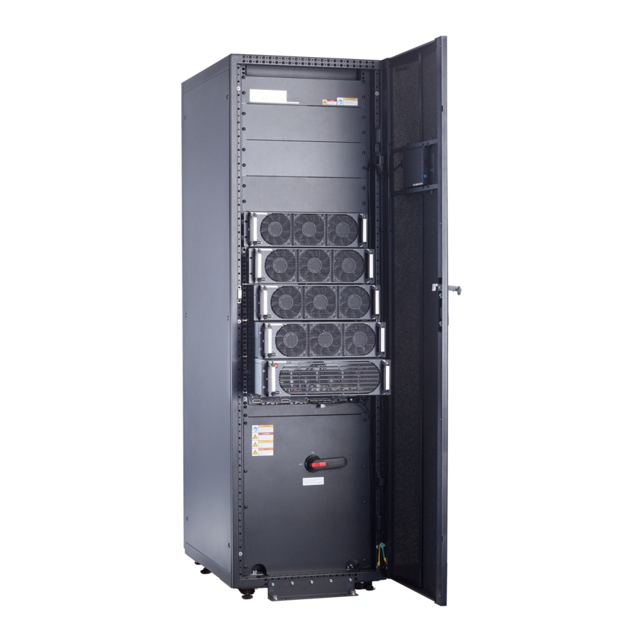
Page 29: Structure
Figure 2-10 Structure with the door open (5+1 in standard configuration) (1) Power (2) Bypass (3) Control module (4) Power distribution modules module subrack cover (5) Monitor (6) Filler (7) Maintenance bypass display unit panels switch Issue 03 (2020-01-10) Copyright © Huawei Technologies Co., Ltd. -
Page 30: Power Module
The module is not configured, the inverter short or rectifier DSP software is being upgraded, intervals or the inverter CPLD software is being upgraded (blinking at 4 Hz, on for 0.125s Issue 03 (2020-01-10) Copyright © Huawei Technologies Co., Ltd. - Page 31 The inverter (DC/AC) converts the inputs into sine wave outputs. Specifications Dimensions (H x W x D): 130 mm x 442 mm x 620 mm Weight: ≤ 35 kg Rated output capacity: 40 kVA/36 kW Issue 03 (2020-01-10) Copyright © Huawei Technologies Co., Ltd.
-
Page 32: Bypass Module
The system is working in bypass mode. Blinking at The bypass has no output (blinking at 0.2 Hz, on for 2.5s and off for 2.5s). long intervals Blinking at The bypass is not configured or the DSP Issue 03 (2020-01-10) Copyright © Huawei Technologies Co., Ltd. - Page 33 If the system runs abnormally, the UPS transfers to bypass mode. The UPS is transferred to bypass mode manually. Specifications Dimensions (H x W x D): 130 mm x 422 mm x 500 mm Weight: < 25 kg Issue 03 (2020-01-10) Copyright © Huawei Technologies Co., Ltd.
-
Page 34: Power Distribution Module
Specifications The power distribution module provides a loading capability of 200 kVA. 2.3.6 Monitoring System 2.3.6.1 Overview The monitoring system consists of a CM and MDU, as described in Table 2-4. Issue 03 (2020-01-10) Copyright © Huawei Technologies Co., Ltd. - Page 35 (3) Indicator (4) Parallel port 2 (5) Indicators (6) Dry contact card (7) Dry contacts (8) MDU port (9) RS485 port (10) Fast Ethernet (FE) port (11) COM2 port (12) COM1 port Issue 03 (2020-01-10) Copyright © Huawei Technologies Co., Ltd.
-
Page 36: Working Principle
The monitoring system reports the system status and key information to the northbound monitoring system or network management system (NMS) over an FE port or RS485 port. The monitoring system provides an RS485 port for additional functions. Issue 03 (2020-01-10) Copyright © Huawei Technologies Co., Ltd. -
Page 37: Ecm
2 Overview Figure 2-16 Position of the monitoring system in the UPS5000 system 2.3.6.3 ECM Appearance The control module consists of two energy control modules (ECMs) in active/standby mode. Figure 2-17 ECM Issue 03 (2020-01-10) Copyright © Huawei Technologies Co., Ltd. - Page 38 Controls the running of a single UPS5000 and a parallel system, and reports the UPS5000 status information to other monitoring modules. The system provides three types of CAN communication: monitoring CAN communication, intra-rack parallel CAN communication, and inter-rack parallel CAN communication. Issue 03 (2020-01-10) Copyright © Huawei Technologies Co., Ltd.
-
Page 39: Dry Contact Card
Port for detecting diesel Connected: D.G. Disconnected generator (D.G.) mode mode Disconnected: Port for signal ground non-D.G. mode BCB_OL Port for detecting the BCB Grounded: BCB Grounded Issue 03 (2020-01-10) Copyright © Huawei Technologies Co., Ltd. - Page 40 SWITCH Port for signal ground circuit breaker STATUS_0V Port for monitoring the input Connected: SPD Connected enabled AC surge protective device (SPD) Disconnected: SPD disabled Port for signal ground Issue 03 (2020-01-10) Copyright © Huawei Technologies Co., Ltd.
-
Page 41: Monitoring Interface Card
FE port, battery temperature monitoring port, and network management port. The MDU monitors the UPS, allows users to set parameters, delivers commands, reports information, and displays the UPS key information and parameters on the LCD. Issue 03 (2020-01-10) Copyright © Huawei Technologies Co., Ltd. - Page 42 Network port Connects to the network port on a PC. Network port for connecting to the web service and for SNMP networking. Northbound RS485 Connects to a northbound network management Issue 03 (2020-01-10) Copyright © Huawei Technologies Co., Ltd.
- Page 43 RS485 cables and FE cables must be shielded cables. Figure 2-21 Figure 2-22 are recommended wiring methods for DO ports. Figure 2-21 Wiring method 1 Figure 2-22 Wiring method 2 Issue 03 (2020-01-10) Copyright © Huawei Technologies Co., Ltd.
- Page 44 UPS5000-S-(40 kVA-200 kVA) User Manual (IP42, 40 kVA Power Modules) 2 Overview Figure 2-23 COM1 pins Table 2-9 COM1 pin definition Description RS485– RS485+ 12V_PORT Issue 03 (2020-01-10) Copyright © Huawei Technologies Co., Ltd.
- Page 45 UPS5000-S-(40 kVA-200 kVA) User Manual (IP42, 40 kVA Power Modules) 2 Overview Figure 2-24 COM2 pins Table 2-10 COM2 pin definition Description RS485+ RS485– RS485+ RS485– CANH0 CANL0 Issue 03 (2020-01-10) Copyright © Huawei Technologies Co., Ltd.
- Page 46 Connect pins 1, 2, 4, and 5. Twist cables to pin 1 and pin 4 into one cable and then connect it to RS485+. Twist cables to pin 2 and pin 5 into one cable and then connect it to RS485–. Issue 03 (2020-01-10) Copyright © Huawei Technologies Co., Ltd.
-
Page 47: Mdu
The UPS is running properly or a warning has been generated. The MDU is powered off. The indicator on the MDU panel is yellow when the bypass supplies power in non-ECO mode. Issue 03 (2020-01-10) Copyright © Huawei Technologies Co., Ltd. - Page 48 View or obtain UPS running information during preventive maintenance. NOTE Only Huawei service engineers or authorized service engineers are allowed to use the WiFi module. To ensure security, remove the WiFi module immediately after use. ...
-
Page 49: Typical Configurations
Energy control modules (ECMs) on each UPS are connected over parallel cables. The parallel connections synchronize the UPS outputs to supply power to loads. If one UPS fails, the other UPSs continue supplying power to loads. Issue 03 (2020-01-10) Copyright © Huawei Technologies Co., Ltd. -
Page 50: Dual-Bus System
An optional static transfer switch (STS) can be installed to start the bus synchronization controller (BSC). The UPS systems work in normal mode or bypass mode. Issue 03 (2020-01-10) Copyright © Huawei Technologies Co., Ltd. -
Page 51: Optional Components
BXA001 Battery bus PDU8000- Converges the energy from PDU8000-(0630, multiple battery strings. bar (BBB) 0630DCV8- 1250, 2000) DCV8- BGA001 BGA001 BBB Box User Manual PDU8000- 1250DCV8- BGA001 PDU8000- Issue 03 (2020-01-10) Copyright © Huawei Technologies Co., Ltd. - Page 52 SOC, and SOH of batteries. Parallel cable 5 m/10 m/15 m Connects UPSs in parallel. BSC cable 5 m/10 m/15 m/60 Transmits bus synchronization signals in a dual-bus system. Issue 03 (2020-01-10) Copyright © Huawei Technologies Co., Ltd.
-
Page 53: Installation
3 Installation Installation 3.1 Dimensions Figure 3-1 Dimensions (unit: mm) (1) Front door (2) Foot (3) Caster (4) Base (5) Rear panel (6) Base installation hole (7) Beam (8) Side beam Issue 03 (2020-01-10) Copyright © Huawei Technologies Co., Ltd. -
Page 54: Installation Environment
Reserve at least 500 mm from the rear of the cabinet for ventilation. If you need to perform operations at the rear of the cabinet, reserve at least 800 mm. Figure 3-2 Reserved clearances (unit: mm) Issue 03 (2020-01-10) Copyright © Huawei Technologies Co., Ltd. -
Page 55: Tools And Instruments
Alloy hole saw Heat gun drill bit Φ16 drill Diagonal pliers Crimping tools Wire stripper Electric hydraulic pliers Clamp meter Multimeter Cable tie Level instrument Polyvinyl chloride Cotton cloth Label Electrician's knife Issue 03 (2020-01-10) Copyright © Huawei Technologies Co., Ltd. - Page 56 (M3/M4/M5/M6/M (M6/M8/M12/M16) Table 3-1 lists only the common tools for installation and cable connection. For more dedicated tools required, see the corresponding component manuals. Prepare tools based on site requirements. Issue 03 (2020-01-10) Copyright © Huawei Technologies Co., Ltd.
-
Page 57: Preparing Power Cables
Recommended 4x25 4x35 4x70 4x120 4x150 cross-sectional area (mm Output Output current (A) Recommended 4x25 4x35 4x70 4x120 4x150 cross-sectional area (mm Battery Nominal battery input discharge current (A) Maximum battery Issue 03 (2020-01-10) Copyright © Huawei Technologies Co., Ltd. - Page 58 13.5 mm 45 mm 46 N· m Bypass input Crimped OT terminal 13.5 mm 45 mm 46 N· m Battery input Crimped OT terminal 13.5 mm 45 mm 46 N· m Issue 03 (2020-01-10) Copyright © Huawei Technologies Co., Ltd.
- Page 59 The upstream input circuit breakers recommended in the table are for reference only. If multiple loads are connected, specifications for branch circuit breakers must not exceed the recommended specifications. Issue 03 (2020-01-10) Copyright © Huawei Technologies Co., Ltd.
-
Page 60: Unpacking And Checking
Step 1 Use a pallet truck to transport the UPS to the installation position. Step 2 Check the UPS packing. Step 3 Hold the sliding plate steady. Cut and remove the binding tapes. Put down the sliding plate gently. Figure 3-3 Removing binding tapes Issue 03 (2020-01-10) Copyright © Huawei Technologies Co., Ltd. - Page 61 Check that all fittings comply with the packing list. If some fittings are missing or do not comply with the packing list, record this information and contact your local Huawei office immediately. Step 7 Remove the L-shaped bracket that secures the cabinet and the pallet, and secure the sliding plate to the pallet by using the two M12 screws that were removed.
-
Page 62: Installing A Single Ups
----End 3.7 Installing a Single UPS 3.7.1 Installing the UPS Cabinet Floor Installation Step 1 Determine the cabinet installation position on the floor based on the securing holes of the cabinet. Issue 03 (2020-01-10) Copyright © Huawei Technologies Co., Ltd. - Page 63 Step 2 Use a hammer drill to drill holes for installing the expansion bolts and then install the expansion sleeves in the holes. Figure 3-8 Expansion bolt composition (1) M12 bolt (2) Spring washer (3) Flat washer (4) Expansion sleeve Issue 03 (2020-01-10) Copyright © Huawei Technologies Co., Ltd.
- Page 64 Step 5 Remove the rear cover from the cabinet and open the front door. Step 6 Remove the four rubber plugs (two at the front and two at the rear) from the bottom of the cabinet. Issue 03 (2020-01-10) Copyright © Huawei Technologies Co., Ltd.
- Page 65 3 Installation Figure 3-10 Removing rubber plugs Step 7 Insert four M12x115 expansion bolts into the expansion bolt holes in the floor, and tighten the expansion bolts. Figure 3-11 Tightening bolts ----End Issue 03 (2020-01-10) Copyright © Huawei Technologies Co., Ltd.
- Page 66 3 Installation Channel Steel Installation Huawei does not provide channel steel or expansion bolts used for securing channel steel. It is recommended that the customer purchase at least 80 mm wide channel steel. Ensure that the distance between the outer surfaces of channel steels is 850 mm and secure the channel steels to the floor using expansion bolts.
-
Page 67: Installing Batteries
Install the batteries from the lower layer to the upper layer to prevent falling over due to imbalance. Procedure Step 1 Install a battery rack and batteries. For details, see the battery installation guide delivered along with batteries. ----End Issue 03 (2020-01-10) Copyright © Huawei Technologies Co., Ltd. -
Page 68: Ups Cable Connection Reference
Choose an appropriate cabling route based on the actual situation. The figure is for reference only. Step 4 Connect the cable with a crimped terminal to the corresponding copper bar. Step 5 Clean foreign matter inside the cabinet. ----End Issue 03 (2020-01-10) Copyright © Huawei Technologies Co., Ltd. -
Page 69: Routing Cables
When connecting battery cables, you do not need to connect neutral wires. Procedure Step 1 Open the front door and remove the cover from the power distribution subrack. Figure 3-14 Removing the cover Issue 03 (2020-01-10) Copyright © Huawei Technologies Co., Ltd. - Page 70 Take out the cable tray cover for signal cables, and remove small covers from the bottom based on site requirements. Figure 3-16 Removing small covers from the bottom of the cabinet Drill holes into the large cover for routing cables. Issue 03 (2020-01-10) Copyright © Huawei Technologies Co., Ltd.
- Page 71 If holes are drilled for routing cables, attach grommet strips to the hole edges to protect cables. Reinstall the removed two small covers on the holes at the rear bottom of the cabinet. Issue 03 (2020-01-10) Copyright © Huawei Technologies Co., Ltd.
- Page 72 UPS5000-S-(40 kVA-200 kVA) User Manual (IP42, 40 kVA Power Modules) 3 Installation Figure 3-18 Installing small covers Step 3 Connect ground cables. Figure 3-19 Grounding : Internal equipotential connection Issue 03 (2020-01-10) Copyright © Huawei Technologies Co., Ltd.
- Page 73 Dual mains Remove the copper bars between mains and bypass input terminals. Figure 3-20 Removing copper bars Figure 3-21 shows the power cables routed from the bottom of the cabinet. Issue 03 (2020-01-10) Copyright © Huawei Technologies Co., Ltd.
- Page 74 Step 5 Route the signal cables on the left side of subracks along the left side of the cabinet and the cables on the right side of subracks along the right side of the cabinet, and then bind the cables to the cabinet, as shown in Figure 3-22. Issue 03 (2020-01-10) Copyright © Huawei Technologies Co., Ltd.
-
Page 75: Installing Optional Components
During parallel installation, you only need to install the shockproof components on the side of the cabinet. Procedure Step 1 Determine the installation position for antiseismic kits. Draw mounting holes in the installation position based on the following figure. Issue 03 (2020-01-10) Copyright © Huawei Technologies Co., Ltd. - Page 76 UPS5000-S-(40 kVA-200 kVA) User Manual (IP42, 40 kVA Power Modules) 3 Installation Figure 3-23 Mounting holes for antiseismic kits Step 2 Remove small baffle plates and blockages from the bolt holes. Issue 03 (2020-01-10) Copyright © Huawei Technologies Co., Ltd.
- Page 77 Step 3 Drill holes for installing expansion bolts and install expansion bolts. Step 4 Secure two antiseismic kits to the front and rear of the cabinet, and secure the front and rear antiseismic kits to the floor using M12 expansion bolts. Issue 03 (2020-01-10) Copyright © Huawei Technologies Co., Ltd.
- Page 78 User Manual (IP42, 40 kVA Power Modules) 3 Installation Figure 3-25 Installing front and rear antiseismic kits Step 5 Install side antiseismic kits and raking struts. Figure 3-26 Installing side antiseismic kits and raking struts ----End Issue 03 (2020-01-10) Copyright © Huawei Technologies Co., Ltd.
-
Page 79: Connecting An Ambient T/H Sensor
Figure 3-27 Connecting a UPS and an ambient T/H sensor The ambient T/H sensor can be used as a battery temperature sensor. ----End 3.7.5.3 Installing a Battery Grounding Failure Detector Procedure Step 1 Install a battery grounding failure detector. Issue 03 (2020-01-10) Copyright © Huawei Technologies Co., Ltd. -
Page 80: Remote Epo
----End 3.7.6 Remote EPO Huawei does not provide the EPO switch or cable. If the cable is required, the recommended cable is 22 AWG. Equip the EPO switch with a protective cover to prevent misoperations, and cover the cable with protective tubing. -
Page 81: Installing A Parallel System
3.8 Installing a Parallel System 3.8.1 Mechanical Installation Procedure Step 1 Install the UPSs in a parallel system using the single UPS installation method. Step 2 Install the top connecting kits. Issue 03 (2020-01-10) Copyright © Huawei Technologies Co., Ltd. -
Page 82: Routing Cables
Step 2 Select a parallel connection method to connect cables for the parallel system based on the site configurations. The typical scenario of a 1+1 parallel system is used as an example. Issue 03 (2020-01-10) Copyright © Huawei Technologies Co., Ltd. - Page 83 Figure 3-33 Cable connections for a 1+1 parallel system (1) Battery (2) Bypass input power (3) Mains input power (4) Output power cables cables cables cables The two subsystems of a bus system are used as an example. Issue 03 (2020-01-10) Copyright © Huawei Technologies Co., Ltd.
- Page 84 (2) Bypass input power (3) Mains input power (4) Output power cables cables cables cables Step 3 Connect the parallel ports on the UPSs using parallel cables to form a loop. Issue 03 (2020-01-10) Copyright © Huawei Technologies Co., Ltd.
- Page 85 Figure 3-36 Topology for a 1+1 parallel system Figure 3-37 shows only control modules. Each control module represents a single UPS. Figure 3-37 Parallel signal cable connections Dual-bus parallel system Issue 03 (2020-01-10) Copyright © Huawei Technologies Co., Ltd.
-
Page 86: Installation Verification
The UPS and its adjacent cabinets are neatly arranged and secured with connecting plates. Cable layout Cables are routed properly and cable routing meets customer requirements. Cable labels Both ends of a cable are labeled. Labels are Issue 03 (2020-01-10) Copyright © Huawei Technologies Co., Ltd. - Page 87 2. After verifying the installation, reinstall all the covers. 3. Do not remove the dustproof cover before power-on to prevent dust inside the UPS. Issue 03 (2020-01-10) Copyright © Huawei Technologies Co., Ltd.
- Page 88 Figure 3-39 Positions for checking foreign matter (1) Cabinet top (2) Wiring terminal (3) Switches (4) Rear of modules blocks Figure 3-40 Fill the holes with sealing putty (1) Paper protective film (2) Sealing putty Issue 03 (2020-01-10) Copyright © Huawei Technologies Co., Ltd.
- Page 89 UPS5000-S-(40 kVA-200 kVA) User Manual (IP42, 40 kVA Power Modules) 3 Installation Figure 3-41 Dustproof cover Issue 03 (2020-01-10) Copyright © Huawei Technologies Co., Ltd.
-
Page 90: User Interface
Figure 4-1 Main menu Table 4-1 Main screen description Number Area Function Status bar Displays the UPS model, capacity, configuration, current date and time, USB flash drive status, and buzzer status. Issue 03 (2020-01-10) Copyright © Huawei Technologies Co., Ltd. - Page 91 Scrolls the page down. Scrolls the page up. Returns to the upper-level menu. Logs a user out. Table 4-3 LCD user passwords Default User Preset Password admin (administrator) 000001 operator (common user) 000001 Issue 03 (2020-01-10) Copyright © Huawei Technologies Co., Ltd.
-
Page 92: System Info
On the System Info, tap the UPS picture. On the Module Data screen, select a module to view its running data. indicates the selected module. Figure 4-3 Module data 4.1.2.2 Running On the System Info screen, tap to access the Runn Info screen. Issue 03 (2020-01-10) Copyright © Huawei Technologies Co., Ltd. - Page 93 AC output frequency Power factor Proportion of output active power to output apparent power. Table 4-5 UPS load Item Description Active power (kW) Output active power of each phase on the UPS. Issue 03 (2020-01-10) Copyright © Huawei Technologies Co., Ltd.
- Page 94 Proportion of the bypass input active power to the bypass input apparent power. Table 4-8 Battery status Item Description Battery Status The value can be Not connected, Equalized charging, Float charging, Hibernating, discharging, or Not chg. or dis. Issue 03 (2020-01-10) Copyright © Huawei Technologies Co., Ltd.
-
Page 95: Alarms
Ambient humid. (%) Humidity measured by the ambient temperature and humidity sensor. If the sensor is not installed, NA is displayed. 4.1.2.3 Alarms on the System Info screen to enter the Alarms screen. Issue 03 (2020-01-10) Copyright © Huawei Technologies Co., Ltd. - Page 96 This screen displays alarm information including the severity, name, ID, location, and generation time. Figure 4-7 Active alarms Historical Alarms This screen displays alarm information including the severity, name, ID, location, generation time, and clear time. Issue 03 (2020-01-10) Copyright © Huawei Technologies Co., Ltd.
-
Page 97: Settings
If this selection is enabled, the buzzer is muted. If the buzzer is enabled, Buzzer Off is displayed on the operation screen. 4.1.2.4 Settings On the System Info screen, tap to access the Settings screen. Figure 4-9 Settings 1 Issue 03 (2020-01-10) Copyright © Huawei Technologies Co., Ltd. - Page 98 UPS5000-S-(40 kVA-200 kVA) User Manual (IP42, 40 kVA Power Modules) 4 User Interface Figure 4-10 Settings 2 Communication Settings Figure 4-11 Communication settings 1 Figure 4-12 Communication settings 2 Issue 03 (2020-01-10) Copyright © Huawei Technologies Co., Ltd.
- Page 99 Ensure that the MDU and PC are on the same network segment. After you restart the device, IP address allocation changes back to Manual. The IP address is set to the IP address set previously. Issue 03 (2020-01-10) Copyright © Huawei Technologies Co., Ltd.
- Page 100 Baud Rate Select a baud rate to match the 9600 9600, 19200, user's network management 115200 conditions onsite. Parity mode Verify the validity of RS485 None None, Odd, Even communication characters. When Issue 03 (2020-01-10) Copyright © Huawei Technologies Co., Ltd.
- Page 101 Default Value Value Range ModbusTCP If Modbus TCP is used for Enable Disable, Enable encryption communication, communication links do not implement encryption or implement encryption based on the selected encryption mode. Issue 03 (2020-01-10) Copyright © Huawei Technologies Co., Ltd.
- Page 102 Number of cascaded ambient 0–4 temperature and humidity sensors Figure 4-17 Battery temperature sensor Item Description Default Value Value Range Start address 16–28 Quantity Number of cascaded battery 0–4 temperature sensors Issue 03 (2020-01-10) Copyright © Huawei Technologies Co., Ltd.
- Page 103 USB port to MAC address identify the WiFi device to which the mobile phone is connected. Password The password for accessing Changeme WiFi. System Settings Figure 4-19 System settings 1 Issue 03 (2020-01-10) Copyright © Huawei Technologies Co., Ltd.
- Page 104 BSC master system and BSC slave system respectively in the BSC master/slave system setting. (The two UPS systems cannot be BSC master systems or BSC slave Issue 03 (2020-01-10) Copyright © Huawei Technologies Co., Ltd.
- Page 105 1 does not have a start delay. The short-distance battery Disable Disable, Enable temperature sensor monitors the ambient temperature near batteries, and ensures that batteries work reliably and securely. Issue 03 (2020-01-10) Copyright © Huawei Technologies Co., Ltd.
- Page 106 Input cur. Specifies whether to enable or Disable Disable, Enable limiting disable input current limiting to protect generators. Input cur. Limits the input current to protect 200% 50%–200% limiting ratio the D.G. Issue 03 (2020-01-10) Copyright © Huawei Technologies Co., Ltd.
- Page 107 If (Hz/s) Output freq. track rate (Hz/s) is slow, the inverter frequency is different from the bypass frequency when the bypass frequency changes. If output is overloaded or the inverter is Issue 03 (2020-01-10) Copyright © Huawei Technologies Co., Ltd.
- Page 108 Bypass When the difference between the ± 2 Hz ± 0.5 Hz to ± 6 Issue 03 (2020-01-10) Copyright © Huawei Technologies Co., Ltd.
- Page 109 When you set parameters, ensure the following: Dis. cur. 0.1C EOD ≥ Dis. cur. 0.3C EOD ≥ Dis. cur. 0.5C EOD ≥ Dis. cur. 1.0C EOD. Figure 4-24 Battery settings 1 Issue 03 (2020-01-10) Copyright © Huawei Technologies Co., Ltd.
- Page 110 Number of Specifies the number of battery 1–4 battery strings strings connected in parallel. Installation A battery maintenance reminder time is displayed when the Issue 03 (2020-01-10) Copyright © Huawei Technologies Co., Ltd.
- Page 111 Shallow dis. Set the proportion of the 10%–50% test dis. ratio discharge capacity to the total discharge capacity. The value is configurable in any mode. Dry Contact Settings Issue 03 (2020-01-10) Copyright © Huawei Technologies Co., Ltd.
- Page 112 Monitoring interface card (MUS05A): provides four routes of configurable output dry contact signals. Dry contact extended card (MUE07A): provides two routes of input signals and one route of output signals. Figure 4-27 Dry contact settings 1 Issue 03 (2020-01-10) Copyright © Huawei Technologies Co., Ltd.
- Page 113 UPS5000-S-(40 kVA-200 kVA) User Manual (IP42, 40 kVA Power Modules) 4 User Interface Figure 4-28 Dry contact settings 2 Figure 4-29 Dry contact settings 3 Figure 4-30 Dry contact settings 4 Issue 03 (2020-01-10) Copyright © Huawei Technologies Co., Ltd.
- Page 114 UPS5000-S-(40 kVA-200 kVA) User Manual (IP42, 40 kVA Power Modules) 4 User Interface Figure 4-31 Dry contact settings 5 Figure 4-32 Dry contact settings 6 Figure 4-33 Dry contact settings 7 Issue 03 (2020-01-10) Copyright © Huawei Technologies Co., Ltd.
- Page 115 DI port executes the specified action, for example, MUE07A DI_4 valid, MUE07A raises an alarm, when the DI port detects a short DI_5 valid circuit. If the DI port valid setting is open, the corresponding Issue 03 (2020-01-10) Copyright © Huawei Technologies Co., Ltd.
- Page 116 DO_5 MUE07A DI_1, MUE07A DI_2, Corresponds to the signal of the input dry contact DI MUE07A DI_3, MUE07A DI_4, on the MUE07A. MUE07A DI_5 User Settings Figure 4-35 User settings 1 Issue 03 (2020-01-10) Copyright © Huawei Technologies Co., Ltd.
-
Page 117: Maintenance
6–20 characters and contain at least two types of characters. 4.1.2.5 Maintenance On the System Info screen, tap to display the Maintenance screen. Issue 03 (2020-01-10) Copyright © Huawei Technologies Co., Ltd. - Page 118 UPS reliability. Battery maintenance includes Forced Equalized Charging, Shallow Dis. Test, and Capacity Test. The next maintenance time displayed on the screen indicates the upcoming time in which to check batteries. Figure 4-38 Battery maintenance Issue 03 (2020-01-10) Copyright © Huawei Technologies Co., Ltd.
- Page 119 Capacity Test Fully discharge batteries. A deep discharge test is conducted to obtain the battery discharge performance data. USB Operations Figure 4-39 USB operations 1 Figure 4-40 USB operations 2 Issue 03 (2020-01-10) Copyright © Huawei Technologies Co., Ltd.
-
Page 120: About
On the About screen, you can view the model, manufacturer, monitoring version, and power version. Figure 4-41 About 4.1.3 System Status On the System Status to view the mains input, bypass input, load, and battery information. Issue 03 (2020-01-10) Copyright © Huawei Technologies Co., Ltd. -
Page 121: Common Functions
UPS5000-S-(40 kVA-200 kVA) User Manual (IP42, 40 kVA Power Modules) 4 User Interface Figure 4-42 System status 4.1.4 Common Functions Figure 4-43 Common functions 1 Figure 4-44 Common functions 2 Issue 03 (2020-01-10) Copyright © Huawei Technologies Co., Ltd. -
Page 122: Webui
Password, and click Login. The preset UPS IP address is 192.168.0.10. You can set the UPS Ethernet IP address on the LCD or WebUI. The value range is 1.0.0.0–223.255.255.255. Issue 03 (2020-01-10) Copyright © Huawei Technologies Co., Ltd. - Page 123 After a user logs in to the WebUI, if another user logs in with the same user name, the current account will be logged out. It is advised to change the password after the first login using User Mgmt. on the Config. page to prevent unauthorized access. ----End Issue 03 (2020-01-10) Copyright © Huawei Technologies Co., Ltd.
-
Page 124: Monitoring
Displays alarms and real-time data, sets parameters, and provides control commands. The Active Alarms page is displayed by default. Information Displays system monitoring information. area 4.2.2.1 Active Alarms On the Active Alarms page, you can view active alarms. Issue 03 (2020-01-10) Copyright © Huawei Technologies Co., Ltd. -
Page 125: Real-Time Data
Figure 4-48 Real-time data 4.2.2.3 Parameter Settings Figure 4-49 Parameter settings System Settings Item Description Default Value Value Range High ambient An alarm is generated when the 40–60 temperature ambient temperature reaches or Issue 03 (2020-01-10) Copyright © Huawei Technologies Co., Ltd. - Page 126 Disable, the system is not allowed to enter ECO mode when the D.G. supplies power to the bypass. Enable or disable the memory Disable Disable, Enable verification check function. If this parameter Issue 03 (2020-01-10) Copyright © Huawei Technologies Co., Ltd.
- Page 127 If this parameter is set to Enable, Enable Disable, Enable with no load the output current is displayed as output 0 when no load is output. The output load rate is displayed as Issue 03 (2020-01-10) Copyright © Huawei Technologies Co., Ltd.
- Page 128 Enable, the bus overvoltage alarm is automatically cleared, and the rectifier and inverter automatically start when the bus voltage recovers (less than 420 V) within Bus overvolt. recovery time. When Bus Issue 03 (2020-01-10) Copyright © Huawei Technologies Co., Ltd.
- Page 129 ECO mode. If this parameter is set to Disable, the preceding detection is not performed. Whether the bypass current is imbalanced does not affect the ECO bypass mode. Issue 03 (2020-01-10) Copyright © Huawei Technologies Co., Ltd.
- Page 130 The battery enters equalized 0.05 0.02–0.08 equalized charge state when the battery charging cur. current exceeds this parameter coef. (C10) value. SOC to start If the SOC is lower than the 0–100 Issue 03 (2020-01-10) Copyright © Huawei Technologies Co., Ltd.
- Page 131 UPS. EOD restart If EOD restart is set to Enable, 1–1440 delay (min) the UPS starts working after the time set for EOD restart delay when the input recovers from the Issue 03 (2020-01-10) Copyright © Huawei Technologies Co., Ltd.
- Page 132 Enable and the remaining capacity is less than the warning threshold. Intelligent If this parameter is set to Enable, Disable Disable, Enable hibernation the intelligent battery hibernation function is enabled. Issue 03 (2020-01-10) Copyright © Huawei Technologies Co., Ltd.
-
Page 133: Communication Settings
(V/cell) than this threshold, the output dry contact will output signals. 4.2.2.4 Communication Settings Figure 4-50 Communication settings 4.2.2.5 Control Figure 4-51 Control Issue 03 (2020-01-10) Copyright © Huawei Technologies Co., Ltd. -
Page 134: Query
On the Logs page, you can set Log to Historical logs, Cap. test logs, or Common test logs, and query or export logs. Historical logs can be exported but not queried. Figure 4-53 Logs 4.2.4 Config. 4.2.4.1 User Management On the home page, choose Config. > User Mgmt. Issue 03 (2020-01-10) Copyright © Huawei Technologies Co., Ltd. -
Page 135: Site Config
If the password complexity check is enabled, the user password is required to be a string of 6–20 characters and contain at least two types of characters. 4.2.4.2 Site Config. On the home page, choose Config. > Site Config. Issue 03 (2020-01-10) Copyright © Huawei Technologies Co., Ltd. - Page 136 Set Email and Alarm Severity and simulate an alarm. Check that the alarm email can be received. Configure Alarm Notification Email Address is used to configure the email address for receiving alarm emails from the monitoring system. Issue 03 (2020-01-10) Copyright © Huawei Technologies Co., Ltd.
-
Page 137: Rccmd
Enable upon first login. After you submit the setting, the page refreshes. The controls such as SSL Encrypted Transmission and Event Configuration will be displayed on the page, as shown in Figure 4-57. Figure 4-56 RCCMD function disabled Issue 03 (2020-01-10) Copyright © Huawei Technologies Co., Ltd. - Page 138 Disable, the RCCMD certificate controls will not be displayed on the page, as shown in Figure 4-59. If SSL Encrypted Transmission is set to Disable, a message indicating there is a risk will be displayed. Issue 03 (2020-01-10) Copyright © Huawei Technologies Co., Ltd.
- Page 139 The MDU supports 17 alarm events, and a maximum of 50 jobs can be added for each event, as shown in Figure 4-60. Figure 4-60 shows the buttons on the Event Configuration page, Table 4-14 describes these buttons. Issue 03 (2020-01-10) Copyright © Huawei Technologies Co., Ltd.
- Page 140 Button for deleting all jobs You can delete all jobs of the event by clicking this button. Figure 4-61 shows the buttons after one event is expanded and Table 4-15 describes these buttons. Issue 03 (2020-01-10) Copyright © Huawei Technologies Co., Ltd.
- Page 141 RCCMD Shutdown: You need to specify the RCCMD client IP address and port. When the RCCMD client receives the job, it will shut down the computer. Issue 03 (2020-01-10) Copyright © Huawei Technologies Co., Ltd.
- Page 142 RCCMD Execute: Specify the RCCMD client IP address, port, and command to be executed. For example, enter SHUTDOWN, and the RCCMD client will shut down the computer after receiving the command. Issue 03 (2020-01-10) Copyright © Huawei Technologies Co., Ltd.
- Page 143 UPS input voltage value (for example, single-phase: 220 V; three-phase A: 220 V, B: 220 V, C: 220 V). Table 4-16 lists the signal names that can be entered. Figure 4-65 RCCMD TRAP Issue 03 (2020-01-10) Copyright © Huawei Technologies Co., Ltd.
- Page 144 RCCMD client once. At X seconds remaining time: When the battery backup time has only X seconds left, the job will be sent to the RCCMD client once. Issue 03 (2020-01-10) Copyright © Huawei Technologies Co., Ltd.
-
Page 145: Managing The Ups By Using The Nms Complying With Rfc1628 Standard
The MIB is in the MDU. Click Download UPS-RFC1628-MIB on the page of the web browser to download the MIB file which allows the third-party NMS to manage the UPS remotely. Issue 03 (2020-01-10) Copyright © Huawei Technologies Co., Ltd. - Page 146 Take the UNMS II of Generex for example. The method for managing the UPS by using the UNMS II is the same as the method for managing other devices by using the UNMS II. For details, see the UNMS II user manual. Issue 03 (2020-01-10) Copyright © Huawei Technologies Co., Ltd.
-
Page 147: Maintenance
4 User Interface 4.2.5 Maintenance Non-professional engineers are not allowed to operate the maintenance page. Maintenance functions include calibration, variable commissioning, upgrade, and data download. Figure 4-69 Calibration Figure 4-70 Commissioning variables Issue 03 (2020-01-10) Copyright © Huawei Technologies Co., Ltd. -
Page 148: Protecting The Server By Using The Rccmd Software
UPS system generates an alarm; executes commands on the RCCMD client. Receives the message "UPS alive check" sent by the RCCMD client and replies with the system status. Issue 03 (2020-01-10) Copyright © Huawei Technologies Co., Ltd. -
Page 149: Rccmd Event Shutdown And Message Sending
Step 4 Configure events. If you set the job type to RCCMD Message under Inverter on, specify the IP address and port of the RCCMD client. The port is 6003 by default. If you need to modify Issue 03 (2020-01-10) Copyright © Huawei Technologies Co., Ltd. -
Page 150: Ups Alive Check Function
CS121/UPSMAN Traps. If by polling CS121/UPSMAN every x seconds... is selected as the method of detecting heartbeats, set the detection method. The default interval is 1800s and detection is performed 100 times, as shown in Figure 4-75. Issue 03 (2020-01-10) Copyright © Huawei Technologies Co., Ltd. - Page 151 User Manual (IP42, 40 kVA Power Modules) 4 User Interface Figure 4-75 Heartbeat detecting mode on the RCCMD client You can also manually detect heartbeat by clicking Run alive check now..Figure 4-76 Detecting heartbeat manually Issue 03 (2020-01-10) Copyright © Huawei Technologies Co., Ltd.
- Page 152 UPS5000-S-(40 kVA-200 kVA) User Manual (IP42, 40 kVA Power Modules) 4 User Interface Figure 4-77 Detecting heartbeat manually and successfully ----End Issue 03 (2020-01-10) Copyright © Huawei Technologies Co., Ltd.
-
Page 153: Operations
Before powering on the UPS, ensure that all the UPS switches and upstream switch are OFF. Procedure Step 1 Close the upstream bypass and mains input switches. After the UPS is powered on, initialization begins. The MDU displays the Huawei logo and an initialization progress bar. ----End 5.1.2 Starting the Inverter... -
Page 154: Initial Startup
Set Output frequency correctly; otherwise, loads may be affected and the UPS may not work properly. High or low charging power tends to shorten the battery lifespan, or even damages batteries. Figure 5-1 Settings Wizard Issue 03 (2020-01-10) Copyright © Huawei Technologies Co., Ltd. - Page 155 The initial WiFi password is Changeme by default. You can change the password by choosing System Info > Settings > Communication > WiFi Password on the MDU. Step 3 Open the Service Expert app on the mobile phone. Issue 03 (2020-01-10) Copyright © Huawei Technologies Co., Ltd.
- Page 156 Same as the user name and password of WebUI accounts. Step 5 After login, tap Power-on password activation on the screen. In the displayed dialog box, tap OK to start the UPS. Issue 03 (2020-01-10) Copyright © Huawei Technologies Co., Ltd.
- Page 157 Step 1 Open the Service Expert app on the mobile phone. Step 2 On the home screen of the app, tap Startup to access the Set Startup screen. Step 3 Set Site and Device Type as required, and tap Offline Activation. Issue 03 (2020-01-10) Copyright © Huawei Technologies Co., Ltd.
- Page 158 The values of the Bar code and Verification in the figure are for reference only. The actual values prevail. Step 5 Enter Bar code and Verification code obtained from the MDU on the Offline Activation screen. Tap Generate PWD to generate a startup password. Issue 03 (2020-01-10) Copyright © Huawei Technologies Co., Ltd.
-
Page 159: Non-Initial Startup
Step 3 In the displayed dialog box, tap Yes to start the inverter. ----End Starting the UPS on the WebUI Step 1 Open a browser (Internet Explorer 11 for example) and choose Tools > Internet Options. Issue 03 (2020-01-10) Copyright © Huawei Technologies Co., Ltd. - Page 160 Figure 5-8 Logging in to the WebUI Step 5 On the home page of the WebUI, choose Monitoring > Control, click Inv. ON, and confirm the operation to start the inverter. Issue 03 (2020-01-10) Copyright © Huawei Technologies Co., Ltd.
-
Page 161: Powering On Loads
A BCB box is installed. Procedure Step 1 On the Settings > Dry Contact Set screen, set MUE05A connection to Enable, and set BCB connection [OL] and Battery breaker [STA] to Enable. Issue 03 (2020-01-10) Copyright © Huawei Technologies Co., Ltd. -
Page 162: Shutting Down And Powering Off The Ups
After the inverter shuts down, the UPS works in bypass mode if the bypass is normal, as shown in Figure 5-11; the UPS supplies no power and the loads power off if the bypass is abnormal, as shown in Figure 5-11. Issue 03 (2020-01-10) Copyright © Huawei Technologies Co., Ltd. - Page 163 Step 3 Open the battery string circuit breaker. If there are multiple battery strings, open the general circuit breaker between battery strings and the UPS and then open the circuit breaker for each battery string. Step 4 Open the upstream mains input and bypass input switches. ----End Issue 03 (2020-01-10) Copyright © Huawei Technologies Co., Ltd.
-
Page 164: Starting The Ups In Battery Mode
Step 4 Press and hold down the BATT START button on the bypass module for at least 2 seconds. The system automatically enters the battery cold start status. The LCD displays the Huawei logo and an initialization progress bar. - Page 165 After the inverter starts, the UPS still works in bypass mode and the inverter is on standby. If the bypass is not normal, the inverter supplies power immediately. If the inverter is not started, and the system is powered off. Issue 03 (2020-01-10) Copyright © Huawei Technologies Co., Ltd.
-
Page 166: Testing Batteries
Step 1 On the home screen of the LCD, choose System Info > Maintenance > Battery Maint. Step 2 Tap Start next to Forced Equalized Charging to start a forced equalized charging test. Issue 03 (2020-01-10) Copyright © Huawei Technologies Co., Ltd. -
Page 167: Shallow Discharge Test
----End Manual Shallow Discharge Test Step 1 On the home screen of the LCD, choose System Info > Maintenance > Battery Maint. Issue 03 (2020-01-10) Copyright © Huawei Technologies Co., Ltd. -
Page 168: Capacity Test
Procedure Step 1 On the home screen of the LCD, choose System Info > Maintenance > Battery Maint. Step 2 Tap Start next to Capacity Test to start a capacity test. Issue 03 (2020-01-10) Copyright © Huawei Technologies Co., Ltd. -
Page 169: Test Data Download
Step 2 On the main screen of the LCD, choose System Info. Tap . The Maintenance screen is displayed. Step 3 Choose USB Operations > Export Logs, and select a log download path. Issue 03 (2020-01-10) Copyright © Huawei Technologies Co., Ltd. -
Page 170: Download Over The Webui
5.6.4.2 Download over the WebUI Procedure Step 1 Log in to the WebUI. Step 2 Choose Query > Logs, select logs from the Log drop-down list box, then click Export to export logs. Issue 03 (2020-01-10) Copyright © Huawei Technologies Co., Ltd. -
Page 171: Transferring To Maintenance Bypass Mode
Procedure Step 1 Transfer the UPS to the bypass mode. Step 2 Turn on the maintenance bypass switch by rotating the handle clockwise 90 degrees so that the handle points leftwards. Issue 03 (2020-01-10) Copyright © Huawei Technologies Co., Ltd. -
Page 172: Transferring From Maintenance Bypass Mode To Normal Mode
The Maint. Breaker closed alarm disappears from the alarm list. Check whether the UPS works in bypass mode by viewing the system running status diagram on the LCD or WebUI. Step 2 Start UPS inverters. ----End Issue 03 (2020-01-10) Copyright © Huawei Technologies Co., Ltd. -
Page 173: Performing Epo
Choose System Info > Alarms > Active Alarms to check that the EPO alarm is cleared. Viewing active alarms on the WebUI Choose Monitoring > Active Alarms to check that the EPO alarm is cleared. Issue 03 (2020-01-10) Copyright © Huawei Technologies Co., Ltd. -
Page 174: Exporting Data
Figure 5-23 Querying historical alarms You do not need to query logs. Choose Query > Logs, click Export, and save the file. Step 2 Click Query, and you can see the corresponding historical alarms. Issue 03 (2020-01-10) Copyright © Huawei Technologies Co., Ltd. - Page 175 UPS5000-S-(40 kVA-200 kVA) User Manual (IP42, 40 kVA Power Modules) 5 Operations Figure 5-24 Exporting historical alarms Step 3 Click Export and save the displayed webpage. ----End Issue 03 (2020-01-10) Copyright © Huawei Technologies Co., Ltd.
-
Page 176: Routine Maintenance
Input voltage: 380 V AC/400 V If the input voltage is environment AC/415 V AC (line voltage) abnormal, check the power grid status and input cable Output voltage: 380 V AC/400 Issue 03 (2020-01-10) Copyright © Huawei Technologies Co., Ltd. -
Page 177: Quarterly Maintenance
The insulation layer of Replace the cables. (between the UPS and the cables is intact and terminals Secure the output power distribution cabinet) are free from black marks terminals. Issue 03 (2020-01-10) Copyright © Huawei Technologies Co., Ltd. -
Page 178: Battery Mainten
When moving batteries, avoid handling the battery upside down, handle batteries gently, and pay attention to personal safety. Keep the battery switch off when installing or maintaining the batteries. Issue 03 (2020-01-10) Copyright © Huawei Technologies Co., Ltd. -
Page 179: Precautions For Battery Maintenance
UPS is excessively long, or the cable diameter is excessively small. 2. Check whether the equalized charging voltage and float Issue 03 (2020-01-10) Copyright © Huawei Technologies Co., Ltd. -
Page 180: Quarterly Maintenance
UPS is backed the fault (for abnormal up to verify that the batteries alarms, see the alarm list). can discharge normally. 2. If the fault persists, contact Huawei technical support. Issue 03 (2020-01-10) Copyright © Huawei Technologies Co., Ltd. -
Page 181: Annual Maintenance
(A torque wrench is used for checking the torque. After checking that the battery screws meet the requirements, mark the screws for later check.) Issue 03 (2020-01-10) Copyright © Huawei Technologies Co., Ltd. -
Page 182: Troubleshooting
Close the battery switch and charge batteries until each battery has a voltage greater than the EOD voltage and 11.3 V/cell. For details about how to rectify common faults, see Table 7-1. If any unmentioned faults occur, see the alarm list chapter, or contact Huawei technical support. Table 7-1 Troubleshooting Case Symptom Possible Cause... - Page 183 The bypass module Reduce the load, or normal. improve ventilation. experiences overtemperature. For details about component replacement and maintenance involved in Troubleshooting and Alarm List, consult Huawei maintenance engineers. Issue 03 (2020-01-10) Copyright © Huawei Technologies Co., Ltd.
-
Page 184: Technical Specifications
The power is derated as described in IEC62040-3 when the altitude is from 1000 m to 4000 m. The upper limit of the altitude is 4000 m. Table 8-3 Safety and EMC Item Specifications Safety EN62040-1:2013 compliance IEC62040-1:2013 Issue 03 (2020-01-10) Copyright © Huawei Technologies Co., Ltd. - Page 185 380 V AC/400 V AC/415 V AC (line voltage) Voltage range 80–280 V AC (phase voltage) At 0–30° C: not derated when the voltage is 176–280 V AC; derated to 40% load when the voltage is 176–80 V Issue 03 (2020-01-10) Copyright © Huawei Technologies Co., Ltd.
- Page 186 30 ≤ Number of batteries < 36: The output power is derated to 0.8. Batteries with no neutral Supported wire Cold start If a mains outage occurs, batteries can start the UPS to supply Issue 03 (2020-01-10) Copyright © Huawei Technologies Co., Ltd.
- Page 187 3 minutes 125% < load ≤ 150%, 30–40° C: transfer to bypass mode after 30s Load > 150% or a short circuit occurs: transfer to bypass mode after 200 ms Issue 03 (2020-01-10) Copyright © Huawei Technologies Co., Ltd.
- Page 188 User Manual (IP42, 40 kVA Power Modules) 8 Technical Specifications Table 8-8 System electrical specifications Item Specifications System efficiency Maximum 97% Parallel system reliability Redundant parallel signals ECO in a parallel system Supported Issue 03 (2020-01-10) Copyright © Huawei Technologies Co., Ltd.
-
Page 189: A Menu Hierarchy
Environment Data Alarms Active Alarms Historical Alarms Buzzer Off Clear Faults Settings Comm Settings IP Settings RS485 Settings ModbusTCP Settings Amb T/H Sensor Batt Temp Sensor WiFi Settings System Settings Input Settings Issue 03 (2020-01-10) Copyright © Huawei Technologies Co., Ltd. - Page 190 Remove USB Inv. ON Inv. OFF ECM Switchover Screen Calib. About Common AC Output Functions UPS Load Mains Input Inv. ON Inv. OFF Buzzer Off Historical Alarms System Status Bypass Mains Load Issue 03 (2020-01-10) Copyright © Huawei Technologies Co., Ltd.
-
Page 191: Menus On The Webui
Basic Param. Advanced Param. Batt. String Config Control System Commands and Tests Query Alarm History Logs Config. User Mgmt. User Mgmt. Idle Timeout Logout Site Config. Time zone System Date and Time Issue 03 (2020-01-10) Copyright © Huawei Technologies Co., Ltd. - Page 192 Certificate Management RCCMD RCCMD SSL Encrypted Transmission Event Configuration RCCMD Certificate Management Maint. Calib Bypass Module Commissioning Var. Bypass Module Upgrade Software BSP Upgrade Download Fault Data CIM version E-Label Issue 03 (2020-01-10) Copyright © Huawei Technologies Co., Ltd.
-
Page 193: B Alarm List
Verify the cable connections. Reversed connections are incorrect. 1. Secure or connect the neutral wire to 0005-1 Mains neutral Minor Cable the cabinet if it is loose or absent connections are disconnected. incorrect. Issue 03 (2020-01-10) Copyright © Huawei Technologies Co., Ltd. - Page 194 Replace the power module. 0021-1 Battery EOD Critical The battery If the BCB box is configured, check voltage reaches whether the BCB box trips. If it trips, close Issue 03 (2020-01-10) Copyright © Huawei Technologies Co., Ltd.
- Page 195 2. Check whether the battery grounding The battery failure detector is faulty by replacing it ground with a new one. monitoring Issue 03 (2020-01-10) Copyright © Huawei Technologies Co., Ltd.
- Page 196 2. Check whether the fans are functioning functioning properly. Replace the power module if properly. the fans are faulty. The air channel for the power module is obstructed. Issue 03 (2020-01-10) Copyright © Huawei Technologies Co., Ltd.
- Page 197 If not all modules generate the alarm, waveform is not start the UPS, transfer it to normal normal. mode, and replace the faulty module. If all modules generate the alarm, open Issue 03 (2020-01-10) Copyright © Huawei Technologies Co., Ltd.
- Page 198 2. Check that the ambient temperature has properly, or not exceeded 40° C. the air 3. Check that there is no overload. channel is blocked. The ambient temperature exceeds the upper threshold. Issue 03 (2020-01-10) Copyright © Huawei Technologies Co., Ltd.
- Page 199 Critical The EPO button Restore the EPO button status. Start the is pressed. UPS after the alarm is cleared. 0086-1 Max. number Minor The system Check the load. of BPM frequently Issue 03 (2020-01-10) Copyright © Huawei Technologies Co., Ltd.
- Page 200 PDC is OFF. 1. Check that all UPS output circuit 0338 PDC output Critical The output breakers are ON. breaker open circuit breaker on the PDC is Issue 03 (2020-01-10) Copyright © Huawei Technologies Co., Ltd.
- Page 201 ECO bypass voltage range, out of the and frequency range are correctly set. preset range. 3. Check that the bypass cables and circuit breakers are correctly The ECO connected. bypass Issue 03 (2020-01-10) Copyright © Huawei Technologies Co., Ltd.
- Page 202 2. After maintenance, open the maintenance circuit breaker and then start the inverter. 0380 In self-check Warning The inverter is Wait until the inverter self-check is in self-check. complete. Issue 03 (2020-01-10) Copyright © Huawei Technologies Co., Ltd.
-
Page 203: C Acronyms And Abbreviations
Conformite Europeenne digital signal processing economy control operation emergency power off energy control module end of discharge fast Ethernet International Electrotechnical Commission liquid crystal display Issue 03 (2020-01-10) Copyright © Huawei Technologies Co., Ltd. - Page 204 THDi total distortion of the input current waveform THDv total harmonic distortion of output voltage uninterruptible power system Universal Serial Bus VRLA valve-regulated lead acid battery Issue 03 (2020-01-10) Copyright © Huawei Technologies Co., Ltd.
Need help?
Do you have a question about the UPS5000-S Series and is the answer not in the manual?
Questions and answers