Huawei UPS5000-S Series Quick Manual
Hide thumbs
Also See for UPS5000-S Series:
- User manual (289 pages) ,
- Quick manual (16 pages) ,
- Quick manual (13 pages)
Table of Contents
Advertisement
Quick Links
UPS5000-S-(650 kVA-800 kVA)
Quick Guide
Issue: 07
Part Number: 31508407
Date: 2020-03-23
1
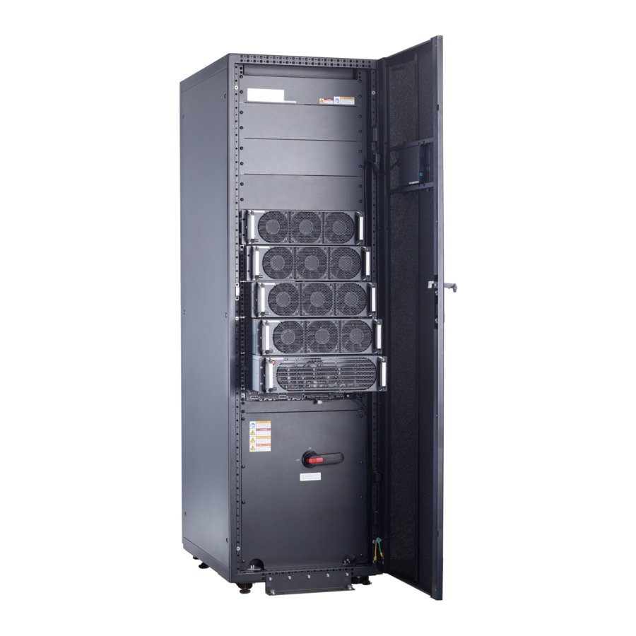
Product Overview
Model
UPS5000-S-800K-SM
UPS5000-S-800K-FM
UPS5000-S-800K-SM
A UPS in standard
configuration has no mains
input switch, bypass input
switch, or output switch.
UPS5000-S-800K-FM
Copyright © Huawei Technologies Co., Ltd. 2020. All rights reserved.
Weight
Dimensions (H x W x D)
1550 kg
2000 mm x 2400 mm x 850 mm
1600 kg
1
(1) Power units
(2) Control module
(3) Maintenance bypass
switch
(4) Power distribution
module cover
(5) Bypass unit
(6) Mains input switch
(7) Output switch
(8) Bypass input switch
Advertisement
Table of Contents

Related Manuals for Huawei UPS5000-S Series


Summary of Contents for Huawei UPS5000-S Series
- Page 1 UPS5000-S-(650 kVA-800 kVA) Quick Guide Issue: 07 Part Number: 31508407 Date: 2020-03-23 Copyright © Huawei Technologies Co., Ltd. 2020. All rights reserved. Product Overview Model Weight Dimensions (H x W x D) UPS5000-S-800K-SM 1550 kg 2000 mm x 2400 mm x 850 mm...
-
Page 2: Installing The Ups
2. Use insulated tools when installing the equipment. 3. Only engineers certified by Huawei or its agent are allowed to install, commission, and maintain the UPS. Otherwise, personal injury or equipment damage may occur, and the resulting UPS faults are beyond the warranty scope of Huawei. - Page 3 1. Move the UPS to the installation position and open the front door of the power cabinet. 2. Install the connecting plates between the bypass cabinet and its adjacent power cabinet based on the following sequence: bottom, top, and middle connecting plates. 3.
- Page 4 4. Install anchor baffle plates. 5. Remove the front cover of the power distribution subrack from the bypass cabinet, and remove the rear covers from the bypass cabinet and its adjacent power cabinet. 7. (Optional) Remove the extension rod of the 6.
- Page 5 8. Cut off the cable ties binding holes of copper bars 9. Remove the filler panel from the numbered 23, 24, 25, 26, and 30. Install the soft power cabinet, and install the soft copper bars in the bypass cabinet and its adjacent copper bar numbered 52.
- Page 6 A UPS in standard configuration has only one switch cable (maintenance bypass switch). A UPS in full configuration has three switch cables (mains input switch, maintenance bypass switch, and bypass input switch). The following figure shows how to connect cables to a parallel system in full configuration.
-
Page 7: Connecting Cables
Connecting Cables 1. This document describes cable routing by removing the top cover when there are two mains inputs. 2. In the case of single mains, you do not need to connect bypass input power cables and remove short-circuit copper bars. UPS Cable Connection Reference •... -
Page 8: Installing Cables
Installing Cables Scenario 1: Routing Cables from the Top 1. Remove the top cover from the cabinet based 2. Remove the copper bar between the mains on cable routes and dimensions. and bypass inputs. (Skip this step if there is only one mains input.) 3. - Page 9 5. Connect output power cables. 6. Connect bypass input power cables. 7. Connect battery cables. 8. Connect the signal cable. The figure shows the signal cable routing and is for reference only. Connect the cable based on the actual 9. Reinstall the extension rod of the situation.
-
Page 10: Verifying The Installation
Scenario 2: Routing Cables from the Bottom 1. Remove the cable covers from the bottom of the cabinet, drill holes in the covers, attach grommet strips to the hole edges for protecting cables, and reinstall the cable covers. 2. Connect power cables and signal cables. For the screw specifications and torque used for connecting cables in a bottom cable routing scenario, refer to the top... -
Page 11: Powering On And Starting The Ups
2. After verifying the installation, reinstall all the covers. 3. (Remove the paper protective film from the sealing putty.) After routing cables and verifying cable connections, seal the gap between cables and the cabinet using sealing putty. Paper protective film Sealing putty Sealing putty must be used as a whole and the gap can be sealed only from the top. -
Page 12: Powering On The Ups
Close the upstream bypass and mains input switches. (Full configuration model) Close the UPS bypass input switch, output switch, and mains input switch. After the UPS is powered on, initialization begins. The MDU displays the Huawei logo and an initialization progress bar. - Page 13 2. Set the language, time, date, network parameters, and system parameters on the Settings Wizard screen. 3. After you perform the settings, the Bypass mode and No battery alarms are reported by the MDU and do not need to be cleared. If there is any other alarm, you need to rectify the fault. 4.
-
Page 14: Shutting Down The Ups
System User LCD Preset Password WebUI Preset Password admin (system administrator) 000001 Changeme operator (common user) 000001 Changeme Powering On Loads 1. After the inverter starts, the UPS works in normal mode. The Bypass mode alarm disappears from the MDU. 2. - Page 15 Scan here for technical support (carrier): Huawei App Store Scan here for more documents: Support-E Support WeChat You can also log in to Huawei technical support website: https://support.huawei.com/enterprise https://support.huawei.com Huawei Technologies Co., Ltd. Huawei Industrial Base, Bantian, Longgang Shenzhen 518129 People's Republic of China...
Need help?
Do you have a question about the UPS5000-S Series and is the answer not in the manual?
Questions and answers