
Related Manuals for Kontron PEP CP321


Summary of Contents for Kontron PEP CP321
- Page 1 CP321 Power PC-based CPU Board for CompactPCI Applications Manual ID: 24977, Rev. Index 02 July 2003 The product described in this manual is in compliance with all applied CE stan- dards.
-
Page 2: Imprint
Copyright © 2003 Kontron Modular Computers GmbH. All rights reserved. This manual may not be copied, photocopied, reproduced, translated or converted to any electronic or machine- readable form in whole or in part without prior written approval of Kontron Modular Computers GmbH. -
Page 3: Table Of Contents
1.6.1 Functional Block Diagram ............... 1 - 9 1.6.2 Frontpanels ................... 1 - 10 1.6.3 Board Layouts ................1 - 11 1.7 Technical Specifications ................ 1 - 12 ID 24977, Rev. 02 © 2003 Kontron Modular Computers GmbH Page iii... - Page 4 System Status Indicators ...............2 - 17 2.4.5 Coding Switch ................2 - 17 2.4.6 Digital Temperature Sensor (LM75) ..........2 - 17 2.4.7 DEBUG Interface and Pinout ............2 - 18 2.5 Options ....................2 - 20 Page iv © 2003 Kontron Modular Computers GmbH ID 24977, Rev. 02...
- Page 5 4.3.11 Event Register ................4 - 15 4.4 UART Registers Address Mapping ............4 - 16 4.4.1 UART A ..................4 - 16 4.4.2 UART B ..................4 - 17 ID 24977, Rev. 02 © 2003 Kontron Modular Computers GmbH Page v...
- Page 6 Uploading a FLASH Area .............. 5 - 11 5.5 Plug and Play ..................5 - 11 5.6 Porting an Operating System to the CPU Board ........5 - 12 5.7 Commands ....................5 - 13 Page vi © 2003 Kontron Modular Computers GmbH ID 24977, Rev. 02...
- Page 7 CP320-TR2 (Optional) .................C - 3 C.1 Board description ..................C - 3 Annex Post Module ....................D - 3 D.1 Board description ..................D - 3 D.2 POST Codes ...................D - 5 ID 24977, Rev. 02 © 2003 Kontron Modular Computers GmbH Page vii...
- Page 8 Preface CP321 Annex PMC-HDD1 Module ..................E - 3 E.1 Board description ..................E - 3 Page viii © 2003 Kontron Modular Computers GmbH ID 24977, Rev. 02...
-
Page 9: List Of Tables
UART A Baud Rate Register Set ............4 - 16 4-17 UART A Enhanced Register Set ............4 - 16 4-18 UART B General Register Set ............... 4 - 17 ID 24977, Rev. 02 © 2003 Kontron Modular Computers GmbH Page ix... - Page 10 Access Addresses for CP320-Post ............D - 3 POST Code LIsting ................D - 5 Pinout of the PMC Connectors ............... E - 4 IDE Hard Disk Drive Connector Pinout ..........E - 5 Page x © 2003 Kontron Modular Computers GmbH ID 24977, Rev. 02...
- Page 11 View of Underside of CP320-TR2 Module ..........C - 4 Plan and Profile Views of CP320-Post Module ........D - 4 PMC-HDD1 Module with Hard Disk Drive Attached ........ E - 3 ID 24977, Rev. 02 © 2003 Kontron Modular Computers GmbH Page xi...
- Page 12 Preface CP321 This page was intentionally left blank. Page xii © 2003 Kontron Modular Computers GmbH ID 24977, Rev. 02...
-
Page 13: Proprietary Note
This document contains information proprietary to Kontron Modular Computers GmbH. It may not be copied or transmitted by any means, disclosed to others, or stored in any retrieval sys- tem or media without the prior written consent of Kontron Modular Computers GmbH or one of its authorized agents. -
Page 14: Explanation Of Symbols
Note... This symbol and title emphasize aspects the reader should read through carefully for his or her own advantage. Page xiv © 2003 Kontron Modular Computers GmbH ID 24977, Rev. 02... -
Page 15: For Your Safety
However, the life expectancy of your product can be drastically reduced by improper treatment during unpacking and installation. Therefore, in the interest of your own safety and of the correct operation of your new Kontron product, you are requested to conform with the following guidelines. -
Page 16: General Instructions On Usage
General Instructions on Usage • In order to maintain Kontron’s product warranty, this product must not be altered or mod- ified in any way. Changes or modifications to the device, which are not explicitly approved by Kontron Modular Computers GmbH and described in this manual or received from Kontron’s Technical Support as a special handling instruction, will void... -
Page 17: Two Year Warranty
However, no other warran- YEAR LIMITED HARDWARE WARRANTY ties that may be granted or implied by anyone on behalf of Kontron are valid unless the con- sumer has the express written consent of Kontron Modular Computers GmbH. - Page 18 Preface CP321 This page was intentionally left blank. Page xviii © 2003 Kontron Modular Computers GmbH ID 24977, Rev. 02...
-
Page 19: Introduction
CP321 Introduction Chapter Introduction ID 24977, Rev. 02 © 2003 Kontron Modular Computers GmbH Page 1 - 1... - Page 20 Introduction CP321 This page was intentionally left blank. Page 1 - 2 © 2003 Kontron Modular Computers GmbH ID 24977, Rev. 02...
-
Page 21: System Overview
• Information on the distinctive features of Kontron CompactPCI boards, such as function- ality, hot swap capability. In addition, an overview is given for all existing Kontron Com- pactPCI boards. • Generic information on the Kontron CompactPCI backplanes, such as the slot assign-... -
Page 22: Product Overview
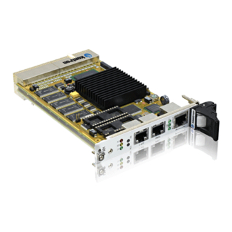
CP321 Product Overview The Kontron Modular Computers’ single-height PowerPC CPU board CP321 is a comprehen- sive computing platform which brings together the latest advances in computing technology in a board designed for maximum performance, flexibility, and versatility within a rugged compact format. -
Page 23: Board Overview
Used as the system controller in a normal CPCI system, the CP321 supports the full range of expansion capabilities as provided via the external CPCI bus. ID 24977, Rev. 02 © 2003 Kontron Modular Computers GmbH Page 1 - 5... - Page 24 • debug interface, JTAG/COP • double and triple-width versions via PMC carriers • compliance with CPCI Specification PICMG 2.0 R 3.0 • operating system: VxWorks, Linux etc. Page 1 - 6 © 2003 Kontron Modular Computers GmbH ID 24977, Rev. 02...
-
Page 25: Optional Modules
The PMC-HDD1 module in conjunction with the CP320-IO1 module provides a cost-effective way to add a mass storage device. It is designed for use with one 2.5” IDE hard disk drive. ID 24977, Rev. 02 © 2003 Kontron Modular Computers GmbH Page 1 - 7... -
Page 26: System Relevant Information
The CP321 can be installed in any CompactPCI 3U or 6U rack. Operating Systems The CP321 can operate under the following operating systems: VxWorks ® Linux Page 1 - 8 © 2003 Kontron Modular Computers GmbH ID 24977, Rev. 02... -
Page 27: Board Diagrams
1x RS485 SUPPLY CPCI INTERFACE 64-bit extension RESET PUSH Rear I/O BUTTON GENERATION EXPANSION CONNECTOR EEPROMS 1x System CPCI 1x User INTERFACE FAST 32-bit PCI Bus ETHERNET ID 24977, Rev. 02 © 2003 Kontron Modular Computers GmbH Page 1 - 9... -
Page 28: Frontpanels
Watchdog (yellow = LED1Y) Halt (red = LED1R) Active (green = LED2AC) Link (green = LED2LN) CP 321 CP 321 SPEED Speed (green = LED2SP) Switches Reset Abort Page 1 - 10 © 2003 Kontron Modular Computers GmbH ID 24977, Rev. 02... -
Page 29: Board Layouts
Figure 1-4: CP321 Board (Reverse View) R28 R25 R22 R29 R27 R24 SDRAM MEMORY BANK 2 R126 R163 R182 R185 R189 R198 R188 R249 R260 R250 ID 24977, Rev. 02 © 2003 Kontron Modular Computers GmbH Page 1 - 11... -
Page 30: Technical Specifications
Two, non-latching, push-button type switches for resetting or halting the system Switch, Coding Freely selectable,16 position, rotary coding switch, the position of which is read out from the coding switch register Page 1 - 12 © 2003 Kontron Modular Computers GmbH ID 24977, Rev. 02... - Page 31 Cascadable PMC carrier board for one PMC module PMC-HDD1 IDE hard drive module (in conjunction with CP320-IO1) Other Via PCI expansion connector other cascadable I/O boards possible ID 24977, Rev. 02 © 2003 Kontron Modular Computers GmbH Page 1 - 13...
-
Page 32: Applied Standards
Introduction CP321 Applied Standards 1.8.1 CE Compliance The Kontron Modular Computers’ CompactPCI systems comply with the requirements of the following CE-relevant standards: • EmissionEN50081-1 • ImmissionEN50082-2 • Electrical SafetyEN60950 1.8.2 Mechanical Compliance • Mechanical DimensionsIEEE 1101.10 1.8.3 Environmental Tests • VibrationIEC68-2-6 Random Vibration, BroadbandIEC68-2-64 (3U boards) •... -
Page 33: Functional Description
CP321 Functional Description Chapter Functional Description ID 24977, Rev. 02 © 2003 Kontron Modular Computers GmbH Page 2 - 1... - Page 34 Functional Description CP321 This page was intentionally left blank. Page 2 - 2 © 2003 Kontron Modular Computers GmbH ID 24977, Rev. 02...
-
Page 35: General Information
• selectable big or little-endian operation (default on the CP321 is big-endian) • store gathering of processor-to-PCI write and PCI-to-memory write accesses • memory prefetching of PCI read accesses • selectable hardware-enforced coherency ID 24977, Rev. 02 © 2003 Kontron Modular Computers GmbH Page 2 - 3... - Page 36 Programmable Memory and PCI Bus Output Drivers Debug Features: • watchpoint monitor • address attribute and PCI attribute signals • JTAG/COP - common onboard processor for in-circuit hardware debugging • performance monitor Page 2 - 4 © 2003 Kontron Modular Computers GmbH ID 24977, Rev. 02...
-
Page 37: Memory
Refer to the current M-Systems data sheets for types available. To prevent these devices from dislodging from their sockets due to shock or vibration it is pos- sible to secure them using a wire strap. ID 24977, Rev. 02 © 2003 Kontron Modular Computers GmbH Page 2 - 5... -
Page 38: Board Interfaces
CPCI J2 connector Tables showing the pinout of the CPCI connectors J1 and J2 appear on the following pages. Z B D F A C E Page 2 - 6 © 2003 Kontron Modular Computers GmbH ID 24977, Rev. 02... -
Page 39: Compactpci Bus Connector J1
AD[22] AD[26] V(I/O) AD[25] AD[24] AD[30] AD[29] AD[28] AD[27] REQ# 3.3V AD[31] BRSVP1A5 BRSVP1B5 RST# GNT# V(I/O) INTP INTS INTA# INTB# INTC# INTD# -12V TRST# +12V ID 24977, Rev. 02 © 2003 Kontron Modular Computers GmbH Page 2 - 7... -
Page 40: Compactpci Bus Connector J2 (64-Bit Version)
AD[57] AD[63] AD[62] AD[61] AD[60] C/BE[5]# V(I/O) C/BE[4]# PAR64 V(I/O) BRSVP2B4 C/BE[7]# C/BE[6]# CLK4 GNT3# REQ4# GNT4# CLK2 CLK3 SYSEN# GNT2# REQ3# CLK1 REQ1# GNT1# REQ2# Page 2 - 8 © 2003 Kontron Modular Computers GmbH ID 24977, Rev. 02... -
Page 41: Compactpci Bus Connector J2 (32-Bit Version)
REQ2# Note... The signal IPMI_PWR (on J1) is routed to 3.3V as it was defined in the preliminary version of the CompactPCI specification PICMG 2.0 R3.0. ID 24977, Rev. 02 © 2003 Kontron Modular Computers GmbH Page 2 - 9... -
Page 42: Ethernet Connector And Pinout
The connector used for the 100BaseTX Ethernet interface is an RJ45 connector. The signals on this connector are as follows Table 2-4: Ethernet Connector Figure 2-2: Ethernet Connector Pinout PIN NUMBER SIGNAL Page 2 - 10 © 2003 Kontron Modular Computers GmbH ID 24977, Rev. 02... -
Page 43: Serial Interfaces And Pinouts
115.2 KBaud. A separate transition module, the CP320-TR1, is also available from Kontron which provides an optoisolated half/full duplex RS485 interface. When installed, this module replaces the stan- dard onboard SER 0 interface along with its associated RJ45 connector. -
Page 44: Serial Interface Expansion Connector And Pinout
• IO board with second Ethernet interface, SCSI etc. Figure 2-2: PCI Expansion Connector (CON11) A table showing the pinout of the PCI Expansion connector appears on the following pages. Page 2 - 12 © 2003 Kontron Modular Computers GmbH ID 24977, Rev. 02... -
Page 45: Pci Expansion Connector Pinout
AD19 V(I/O) AD18 AD17 AD16 C/BE2# FRAME# IRDY# +3.3V TRDY# DEVSEL# reserved STOP# LOCK# +3.3V PERR# V(I/O) SERR# C/BE1# AD15 AD14 +3.3V AD13 AD12 AD11 AD10 ID 24977, Rev. 02 © 2003 Kontron Modular Computers GmbH Page 2 - 13... -
Page 46: Memory Expansion Connectors
Optionally, Socket 2 can be expanded to 36 pins to allow the use of 1 MB or 2 MB NVSRAM from Dallas Semi- conductor (DS1265/70). (18) (19) Page 2 - 14 © 2003 Kontron Modular Computers GmbH ID 24977, Rev. 02... -
Page 47: Dil 32 Pinout For Various Devices
SRAM Eprom Eprom SRAM OnChip Flash Table 2-9: DIL 36 Pinout for 1 MB and 2 MB NVSRAM Devices (Dallas Semiconductor 12654 and 1270Y) SRAM SRAM ID 24977, Rev. 02 © 2003 Kontron Modular Computers GmbH Page 2 - 15... -
Page 48: Special Board Functions
(green) is blinking causes the bootstrap loader to enter interactive command mode. Commands can then be entered for processing by the bootstrap loader. Refer to chapter 5 for Bootstrap Loader infor- mation. Page 2 - 16 © 2003 Kontron Modular Computers GmbH ID 24977, Rev. 02... -
Page 49: System Status Indicators
I²C bus. This is can be used, for example, to maintain the calibration of the onboard RTC over a wide operational temperature range. Refer to chapter 4, DTS Register, for further details. ID 24977, Rev. 02 © 2003 Kontron Modular Computers GmbH Page 2 - 17... -
Page 50: Debug Interface And Pinout
As shipped, only the Altera onboard logic can be detected by means of the JTAG interface. If the JTAG interface requires to be reconfigured for software debugging, please contact Support at Kontron Modular Computers for assistance. Page 2 - 18 ©... -
Page 51: Jtag Chain Resistor Settings
Not Installed ALTERA Installed Not Installed CPU + ALTERA Installed Not Installed ALTERA + 21154 Installed Not Installed Installed CPU + ALTERA + 21154 Not Installed ID 24977, Rev. 02 © 2003 Kontron Modular Computers GmbH Page 2 - 19... -
Page 52: Options
In addition to the above options there is a special test/debug adapter, the CP320-Post, and a rear I/O module, the CP-RIO3-01, which can be obtained on request. Please contact your nearest sales representative for further information. Page 2 - 20 © 2003 Kontron Modular Computers GmbH ID 24977, Rev. 02... -
Page 53: Installation
CP321 Installation Chapter Installation ID 24977, Rev. 02 © 2003 Kontron Modular Computers GmbH Page 3 - 1... - Page 54 Installation CP321 This page was intentionally left blank. Page 3 - 2 © 2003 Kontron Modular Computers GmbH ID 24977, Rev. 02...
-
Page 55: Board Installation
Placement of the CP321 The Kontron CompactPCI system configuration is characterized by the fact that its system slot (slot “1”) is on the right end of the backplane, thus allowing for physical CPU growth (heat-sink, cooling fan, PCI expanson modules, etc.) associated with higher-performance processors. -
Page 56: Front Panel I/O Connectors
TR1 RS485 optoisolated transition module are assembled with the CP321 main board. Assem- bly of the second carrier board follows on top of first carrier board. Figure 3-1: CP321 and Options Assembly Page 3 - 4 © 2003 Kontron Modular Computers GmbH ID 24977, Rev. 02... -
Page 57: Software Installation
CP321 Installation Software Installation Software installation is a function of the Bootstrap Loader and is described in chapter 5 of this manual. ID 24977, Rev. 02 © 2003 Kontron Modular Computers GmbH Page 3 - 5... - Page 58 Installation CP321 This page was intentionally left blank. Page 3 - 6 © 2003 Kontron Modular Computers GmbH ID 24977, Rev. 02...
-
Page 59: Configuration
CP321 Configuration Chapter Configuration ID 24977, Rev. 02 © 2003 Kontron Modular Computers GmbH Page 4 - 1... - Page 60 Configuration CP321 This page was intentionally left blank. Page 4 - 2 © 2003 Kontron Modular Computers GmbH ID 24977, Rev. 02...
-
Page 61: Jumper And Resistor Settings
At NO TIME is J2 to be jumpered (short circuited). This is a test point and operation with a jumper installed will cause damage to the RTC. ID 24977, Rev. 02 © 2003 Kontron Modular Computers GmbH Page 4 - 3... -
Page 62: Resistor Settings For Non-Standard Socket Devices
Flash / DiskOnChip (default) Open Open Open Open NVSRAM Open Open Open Open 4 Mbit EPROM Open Open Open Open Note... All resistors are 0 ohm. Page 4 - 4 © 2003 Kontron Modular Computers GmbH ID 24977, Rev. 02... -
Page 63: Board Address Map
0xFF00 0000 PCI Interrupt Ack 0xFEF0 0000 Configuration DATA 0xFEE0 0000 Configuration Adrress 0xFEC0 0000 0xFEC0 0000 0x8000 0000 RESERVED 0x4000 0000 DRAM 0x0000 0000 ID 24977, Rev. 02 © 2003 Kontron Modular Computers GmbH Page 4 - 5... -
Page 64: Cp321 Upper Area Address Map
0xFFE0 0000 Installed Removed Boot Strap / Loader Jumper - J1 Note... Write access to the upper area addresses is only possible using byte- wide write commands. Page 4 - 6 © 2003 Kontron Modular Computers GmbH ID 24977, Rev. 02... -
Page 65: Board Control Registers
Watchdog Control Register 0xFFE0 0018 Interrupt Enable Register 0xFFE0 0019 Control Register 0xFFE0 001A Coding Switch Register 0xFFE0 001B Event Register 0xFFE0 001C Board/Logic Revision 0xFFE0 001E ID 24977, Rev. 02 © 2003 Kontron Modular Computers GmbH Page 4 - 7... -
Page 66: Board Id Register
Boot Strap Loader and BSP software, and as such, is not user relevant. Table 4-5: Software Compatibility ID REGISTER NAME SOFTWARE COMPATIBILITY ID ACCESS ADDRESS 0xFFE0 0012 BIT POSITION CONTENT DEFAULT Page 4 - 8 © 2003 Kontron Modular Computers GmbH ID 24977, Rev. 02... -
Page 67: Memory Configuration Register
ECC enabled reserved reserved Boot Jumper J1 closed (CP321 fetches boot code from socket 1) Boot Jumper J1 open (CP321 fetches boot code from onboard flash) ID 24977, Rev. 02 © 2003 Kontron Modular Computers GmbH Page 4 - 9... -
Page 68: Flash Bank Select Register
• a 1 in bit 1 (SB1) provides address A20 for the NVSRAM. Table 4-8: SRAM Bank Select Register REGISTER NAME SRAM BANK SELECT ACCESS ADDRESS 0xFFE0 0017 BIT POSITION CONTENT res. res. res. res. res. res. DEFAULT Page 4 - 10 © 2003 Kontron Modular Computers GmbH ID 24977, Rev. 02... -
Page 69: Watchdog Control Register
Causes generation of a non-maskable interrupt upon Watchdog timeout Watchdog timer disabled Watchdog timer enabled Note... WD_EN Once the Watchdog timer is enabled it cannot be disable except by resetting the system. ID 24977, Rev. 02 © 2003 Kontron Modular Computers GmbH Page 4 - 11... -
Page 70: Interrupt Enable Register
Assertion of the power supply failure signal FAL cannot result in an interrupt FAL_EN Assertion of the power supply failure signal FAL results in an interrupt Reserved Page 4 - 12 © 2003 Kontron Modular Computers GmbH ID 24977, Rev. 02... -
Page 71: Control Register
When setting bit 7 care must be taken to ensure that the installed interface corre- sponds to the bit setting. A mismatch may cause damage to the CP321 or the application. ID 24977, Rev. 02 © 2003 Kontron Modular Computers GmbH Page 4 - 13... -
Page 72: Coding Switch Register
/ logic release. Table 4-13:Board Logic / Revision Register REGISTER NAME BOARD LOGIC/REVISION ACCESS ADDRESS 0xFFE0 001E BIT POSITION CONTENT DEFAULT Page 4 - 14 © 2003 Kontron Modular Computers GmbH ID 24977, Rev. 02... -
Page 73: Event Register
Indicates that a Watchdog timeout has occurred reserved Indicates that the Abort switch has not been pressed Indicates that the Abort switch has been pressed reserved reserved reserved reserved reserved ID 24977, Rev. 02 © 2003 Kontron Modular Computers GmbH Page 4 - 15... -
Page 74: Uart Registers Address Mapping
Enhanced Mode Select Register Enhanced Mode Select Register 0xFFE0 0007 Xon-1 Xon-1 0xFFE0 0004 Xon-2 Xon-2 0xFFE0 0005 Xoff-1 Xoff-1 0xFFE0 0006 Xoff-2 Xoff-2 0xFFE0 0007 Page 4 - 16 © 2003 Kontron Modular Computers GmbH ID 24977, Rev. 02... -
Page 75: Uart B
Enhanced Mode Select Register Enhanced Mode Select Register 0xFFE0 000B Xon-1 Xon-1 0xFFE0 000C Xon-2 Xon-2 0xFFE0 000D Xoff-1 Xoff-1 0xFFE0 000E Xoff-2 Xoff-2 0xFFE0 000F ID 24977, Rev. 02 © 2003 Kontron Modular Computers GmbH Page 4 - 17... -
Page 76: Irq Routing
INTB# (PCI) S_IRQ5 INTC# (PCI) S_IRQ6 INTD# (PCI) S_IRQ7 TEMP_INT (Temperature Interrupt) S_IRQ8 reserved S_IRQ9 ENUM S_IRQ10 reserved S_IRQ11 reserved S_IRQ12 reserved S_IRQ13 S_IRQ14 S_IRQ15 reserved Page 4 - 18 © 2003 Kontron Modular Computers GmbH ID 24977, Rev. 02... -
Page 77: Real-Time Clock
When the RTC has once been stopped due to low voltage, it is neces- sary to re-initialize the “Seconds” “Minutes” and “Hours” registers before it will run again. ID 24977, Rev. 02 © 2003 Kontron Modular Computers GmbH Page 4 - 19... -
Page 78: Eeprom's
MPC8245. The DTS uses the I2C address 0x90. For more detailed information please refer to the manuals for the National Semiconductor LM75 and the MOTOROLA MPC8245 (I2C bus). Page 4 - 20 © 2003 Kontron Modular Computers GmbH ID 24977, Rev. 02... - Page 79 CP321 Configuration ID 24977, Rev. 02 © 2003 Kontron Modular Computers GmbH Page 4 - 21...
- Page 80 Configuration CP321 This page was intentionally left blank. Page 4 - 22 © 2003 Kontron Modular Computers GmbH ID 24977, Rev. 02...
-
Page 81: Netbootloader
CP321 NetBootLoader Chapter NetBootLoader ID 24977, Rev. 02 © 2003 Kontron Modular Computers GmbH Page 5 - 1... - Page 82 NetBootLoader CP321 This page has been intentionally left blank. Page 5 - 2 © 2003 Kontron Modular Computers GmbH ID 24977, Rev. 02...
-
Page 83: General Operation
“abort” command via the TERM interface, or by performing a successful telnet lo- gin via the Ethernet interface. If the operator does not intervene, the boot operation is continued after the boot wait time has been exceeded. ID 24977, Rev. 02 © 2003 Kontron Modular Computers GmbH Page 5 - 3... -
Page 84: Mc1 (Abort) Signal
The command title (CMD TITLE) is expressed in capital letters and is not the same as the syntax of the command. The command syntax is always written using small letters Page 5 - 4 © 2003 Kontron Modular Computers GmbH ID 24977, Rev. 02... -
Page 85: Netbootloader Control
Display system information Memory Display memory contents Applies to all visible memory Display Display PCI device information PING Verify network status Version Display version number of NetBootLoader ID 24977, Rev. 02 © 2003 Kontron Modular Computers GmbH Page 5 - 5... -
Page 86: Ftp Server Access
Table 5-5: Motorola S-Records Commands CMD TITLE ALIAS FUNCTION REMARKS SLoad Download Motorola S-Records Uses data buffer as target Page 5 - 6 © 2003 Kontron Modular Computers GmbH ID 24977, Rev. 02... -
Page 87: Operating The Netbootloader
CPU board, the system must either be cold started or the operator must issue a “reset” command. In either event, the NetBootLoader is restarted and the boot operation begins anew. ID 24977, Rev. 02 © 2003 Kontron Modular Computers GmbH Page 5 - 7... -
Page 88: Netbootloader Configuration
This command is used to set the password used by the NetBootLoader for the operation of the telnet interface. No password is required for access from the TERM interface. Page 5 - 8 © 2003 Kontron Modular Computers GmbH ID 24977, Rev. 02... -
Page 89: Telnet Login
The application image itself must be compiled and linked to run from the SDRAM base address 0x0 of the CPU. The image must contain executable PPC code at offset 0x100 which is the usual case with ROM/Flash images. ID 24977, Rev. 02 © 2003 Kontron Modular Computers GmbH Page 5 - 9... - Page 90 RAM during startup and is exe- cuted there. For this reason application images which require to be programmed must start at the address 0x0. Page 5 - 10 © 2003 Kontron Modular Computers GmbH ID 24977, Rev. 02...
-
Page 91: Updating The Netbootloader
This important feature has the advantage that con- flicts do not arise when PCI devices are added or removed. Furthermore, the operating system itself does not include the board initialization code. ID 24977, Rev. 02 © 2003 Kontron Modular Computers GmbH Page 5 - 11... -
Page 92: Porting An Operating System To The Cpu Board
If it is necessary to relocate the image to another address after download, simply add a small assembly routine at the beginning of the code which will move the image to the correct address. Page 5 - 12 © 2003 Kontron Modular Computers GmbH ID 24977, Rev. 02... -
Page 93: Commands
Set or display the parameters of the boot wait function of the NetBootLoader SYNTAX: bw [<time>| -f] where: command <time> parameter: value: seconds 1, 2, 5, 10, 20, 50 option: force CRC update ID 24977, Rev. 02 © 2003 Kontron Modular Computers GmbH Page 5 - 13... - Page 94 FUNCTION: Terminate an ftp server session SYNTAX: DESCRIPTION: An ftp server session which has been established with the command “login” is terminated with the command “bye”. Page 5 - 14 © 2003 Kontron Modular Computers GmbH ID 24977, Rev. 02...
- Page 95 “check” command is used to verify that the current application image in FLASH is valid. USAGE: Veriy valid application is stored in FLASH COMMAND / RESPONSE: check Check userimage CRC: ok ID 24977, Rev. 02 © 2003 Kontron Modular Computers GmbH Page 5 - 15...
- Page 96 Bootjumper is removed. NetBtLd> Note: When responding to the overwrite query, “yes” must be spelled out. Any other response will terminate the cloning operation. Page 5 - 16 © 2003 Kontron Modular Computers GmbH ID 24977, Rev. 02...
- Page 97 The argument may also include a path specification, if the server supports this. ID 24977, Rev. 02 © 2003 Kontron Modular Computers GmbH Page 5 - 17...
- Page 98 The command “info” is used to display an information summary for the running system. The CPU type, the board type, and the detected FLASH layout are displayed. Page 5 - 18 © 2003 Kontron Modular Computers GmbH ID 24977, Rev. 02...
- Page 99 If “<offset>” is specified, the contents are programmed exactly at this offset in FLASH. No length and no CRC information is added. The “-k” option can be specified to prevent deletion of the surrounding FLASH contents. ID 24977, Rev. 02 © 2003 Kontron Modular Computers GmbH Page 5 - 19...
- Page 100 COMMAND / RESPONSE (none): lf -m=87000000 -l=123456 Program FLASH from data buffer to offset 0xF4240 and retain adjacent FLASH contents COMMAND / RESPONSE (none): lf -o=f4240 -k Page 5 - 20 © 2003 Kontron Modular Computers GmbH ID 24977, Rev. 02...
- Page 101 “logout”. No application is loaded and started if the session is terminated with “logout”. The NetBootLoader waits for a new session to be initiated or for a command entry from the serial console. ID 24977, Rev. 02 © 2003 Kontron Modular Computers GmbH Page 5 - 21...
- Page 102 If issued again without the “<adr>” parameter, the display starts with the end address of the previous display. Data is displayed as hexadecimal 32-bit words and as ASCII dump. Page 5 - 22 © 2003 Kontron Modular Computers GmbH ID 24977, Rev. 02...
- Page 103 CRC. This is done automatically. Only in the event that the Ethernet interface does not properly initialize, may it be necessary to re-enter the parameters using the “-f” option. ID 24977, Rev. 02 © 2003 Kontron Modular Computers GmbH Page 5 - 23...
- Page 104 (The old password must be known) Set password when the old password is not known COMMAND / RESPONSE: NetBtLd> passwd New Password: ***** Type again : ***** NetBtLd> Page 5 - 24 © 2003 Kontron Modular Computers GmbH ID 24977, Rev. 02...
- Page 105 <parity> parameter: string: “n” (none), “o” (odd), “e” (even) defines parity to be used <stops> parameter: value: number: “1”, “2” defines number of stop bits ID 24977, Rev. 02 © 2003 Kontron Modular Computers GmbH Page 5 - 25...
- Page 106 Set the bits per character parameter of “SER0” to 7 COMMAND / RESPONSE (none): pf ser0 //7 Set the stop bits parameter of “SER0” to 2 COMMAND / RESPONSE (none): pf ser0 ///2 Page 5 - 26 © 2003 Kontron Modular Computers GmbH ID 24977, Rev. 02...
- Page 107 COMMAND / RESPONSE: ping 192.192.158.7 Send ten packets, 100 bytes long, and wait two seconds between packets COMMAND / RESPONSE: ping 192.192.158.7 -c 10 -s 100 -w 2 ID 24977, Rev. 02 © 2003 Kontron Modular Computers GmbH Page 5 - 27...
- Page 108 If a ftp connection has been established with the “login” command, the command “pwd” is used to display the complete path of the current directory on the ftp server. FUNCTION: Reset the system SYNTAX: Page 5 - 28 © 2003 Kontron Modular Computers GmbH ID 24977, Rev. 02...
- Page 109 USAGE: Store 64 kB of FLASH contents to the data buffer beginning at an offset of 1 MB COMMAND / RESPONSE (none): sf -o=100000 -l=10000 ID 24977, Rev. 02 © 2003 Kontron Modular Computers GmbH Page 5 - 29...
- Page 110 Download S-Records to data buffer and reduce each record’s address by 0x10000. COMMAND / RESPONSE (none): sl -o=10000 FUNCTION: Display version number SYNTAX: DESCRIPTION: The command “ver” displays the actual version number of the NetBootLoader. Page 5 - 30 © 2003 Kontron Modular Computers GmbH ID 24977, Rev. 02...
- Page 111 CP321 CP320-IO1 Module Chapter CP320-IO1 Module ID 24977, Rev. 02 © 2003 Kontron Modular Computers GmbH Page A - 1...
- Page 112 CP320-IO1 Module CP321 This page was intentionally left blank. Page A - 2 © 2003 Kontron Modular Computers GmbH ID 24977, Rev. 02...
-
Page 113: Cp320-Io1 Module
CP320-IO1 Module CP320-IO1 Module A.1. Overview The optional Kontron CP320-IO1 module has been designed to provide the CP321 user with an effective gateway to the world of PMC modules. This additional capability opens up the broadest range of expansion possibilities. -
Page 114: A.2. Board Interfaces
PMC module. The interface has been designed to comply with the IEEE 1386.1 specification which defines a PCI electrical interface for the CMC (Common Mezzanine Card) form factor. Page A - 4 © 2003 Kontron Modular Computers GmbH ID 24977, Rev. 02... -
Page 115: A.3. Board Layout
PMC module. The CON3 connector in conjunction with the CON2 connector (on reverse side of board) make board stacking possible Figure A-1: Board Layout (Front View) MAGNIFIED CON3 PCI EXPANSION CONNECTOR ID 24977, Rev. 02 © 2003 Kontron Modular Computers GmbH Page A - 5... -
Page 116: A.4. Cp320-Io1 Front Panel
A.4. CP320-IO1 Front Panel Figure A-2: CP320-IO1 Front Panel The CP320-IO1 front panel is provided with a window for the insertion of a PMC module bezel. Page A - 6 © 2003 Kontron Modular Computers GmbH ID 24977, Rev. 02... -
Page 117: A.5. Pinouts
C/BE[0]# AD[07] PMC-RSVD AD[06] AD[05] +3.3V PMC-RSVD AD[04] Ground PMC-RSVD Ground V(I/O) AD[03] PMC-RSVD PMC-RSVD AD[02] AD[01] Ground PMC-RSVD AD[00] ACK64# +3.3V Ground REQ64# Ground PMC-RSVD ID 24977, Rev. 02 © 2003 Kontron Modular Computers GmbH Page A - 7... -
Page 118: Pci Expansion Connector (Con2/3) Pinout
AD28 AD27 AD26 AD25 +3.3V AD24 C/BE3# SDA (I2C) AD23 +3.3V AD22 AD21 AD20 AD19 V(I/O) AD18 AD17 AD16 C/BE2# FRAME# IRDY# +3.3V TRDY# DEVSEL# reserved Page A - 8 © 2003 Kontron Modular Computers GmbH ID 24977, Rev. 02... - Page 119 SERR# C/BE1# AD15 AD14 +3.3V AD13 AD12 AD11 AD10 C/BE0# +3.3V reserved +12V -12V 1) Ground 4) +12V 2) +3.3V 5) -12V 3) +5V 6) V(I/O) ID 24977, Rev. 02 © 2003 Kontron Modular Computers GmbH Page A - 9...
-
Page 120: A.6. Technical Specifications
Permanent Shock IEC68-2-29 Single Shock IEC68-2-27 Board Dimensions Single-height Eurocard: 100 mm x 160 mm 1 x 4 HP slot Board Weight 122 grams without PMC module Page A - 10 © 2003 Kontron Modular Computers GmbH ID 24977, Rev. 02... -
Page 121: A.7. Board Installation
6 mm) to secure the board to the CP321 Note... For further information regarding the installation of the CP320-IO1 board refer to the CP321 Installation chapter. ID 24977, Rev. 02 © 2003 Kontron Modular Computers GmbH Page A - 11... -
Page 122: Installation Of Pmc Module
CP320-IO1 Module CP321 Figure A-3: Installation of PMC Module PMC module CP320-IO1 Front Panel CP320-IO1 10mm stand-off PMC bezel 4 *M2.5 *6mm screws Page A - 12 © 2003 Kontron Modular Computers GmbH ID 24977, Rev. 02... - Page 123 TR1 RS485 optoisolated transition module are assembled with the CP321 main board. Assem- bly of the second carrier board follows on top of first carrier board. Figure A-4: CP321 and Options ID 24977, Rev. 02 © 2003 Kontron Modular Computers GmbH Page A - 13...
-
Page 124: A.8. Jumper Setting
CP321 in position P2. Figure A-5: Cascading of IO1 (or other) Modules onto the CP321 RS T P1: 1 additional module P2: 2 additional modules LNK. ACT. SPEE D Page A - 14 © 2003 Kontron Modular Computers GmbH ID 24977, Rev. 02... - Page 125 CP321 CP320-TR1 (Optional) Chapter CP320-TR1 (Optional) ID 24977, Rev. 02 © 2003 Kontron Modular Computers GmbH Page B - 1...
- Page 126 CP320-TR1 (Optional) CP321 This page was intentionally left blank. Page B - 2 © 2003 Kontron Modular Computers GmbH ID 24977, Rev. 02...
-
Page 127: Cp320-Tr1 (Optional)
Table B-2: Serial Port Pinout RS485 CON6 SIGNAL RJ45 HALF-DUPLEX FULL-DUPLEX (Serial) -RxD +TRXD -TxD +RxD -TRXD +TxD Refer to the Functional Description chapter for the pinout of CON3. ID 24977, Rev. 02 © 2003 Kontron Modular Computers GmbH Page B - 3... - Page 128 CP320-TR1 (Optional) CP321 Table B-3: CP320-TR1 Jumper Settings JUMPER SETTING FUNCTION 120 ohm termination, full-duplex 120 ohm termination, Open half-duplex No termination Open Open Page B - 4 © 2003 Kontron Modular Computers GmbH ID 24977, Rev. 02...
- Page 129 CP321 CP320-TR2 (Optional) Chapter CP320-TR2 (Optional) ID 24977, Rev. 02 © 2003 Kontron Modular Computers GmbH Page C - 1...
- Page 130 CP320-TR2 (Optional) CP321 This page was intentionally left blank. Page C - 2 © 2003 Kontron Modular Computers GmbH ID 24977, Rev. 02...
-
Page 131: Cp320-Tr2 (Optional)
• RxD - Receive Data • RTS - Request to Send (used on PC based systems for hardware handshaking) • CTS - (used on PC and Kontron systems for hardware handshaking) • DTR - (used on Kontron systems for hardware handshaking) The board itself is available in the E2 temperature range. -
Page 132: View Of Underside Of Cp320-Tr2 Module
Serial Port Pinout Table C-1: Serial Port Pinout RS232 Signal CON3 ISO-GND CON6 RJ45 (Serial) Please note that this diagram is not to scale with other board diagrams Page C - 4 © 2003 Kontron Modular Computers GmbH ID 24977, Rev. 02... -
Page 133: Post Module
CP321 Post Module Chapter Post Module ID 24977, Rev. 02 © 2003 Kontron Modular Computers GmbH Page D - 1... - Page 134 Post Module CP321 This page was intentionally left blank. Page D - 2 © 2003 Kontron Modular Computers GmbH ID 24977, Rev. 02...
-
Page 135: Board Description
When installing and operating the CP320-Post module ensure that the module does not make contact with the front panel or any other portions of the CP321 except the connections to the DIL socket. ID 24977, Rev. 02 © 2003 Kontron Modular Computers GmbH Page D - 3... -
Page 136: Plan And Profile Views Of Cp320-Post Module
Post Module CP321 Figure D-1: Plan and Profile Views of CP320-Post Module PLAN Number Display PROFILE NUMBER DISPLAY Higher Power Lower Power Page D - 4 © 2003 Kontron Modular Computers GmbH ID 24977, Rev. 02... -
Page 137: Post Codes
47 PR_PCI_UNII PCI configure universe 2 50 PR_CROOT_ENTER CROOT entry 51 PR_CROOT_EXPT CROOT exception handler installed 52 PR_CROOT_FLDET CROOT flash detected 53 PR_CROOT_KEYF CROOT startkey search ID 24977, Rev. 02 © 2003 Kontron Modular Computers GmbH Page D - 5... - Page 138 Post Module CP321 This page was intentionally left blank. Page D - 6 © 2003 Kontron Modular Computers GmbH ID 24977, Rev. 02...
- Page 139 CP321 PMC-HDD1 Module Chapter PMC-HDD1 Module ID 24977, Rev. 02 © 2003 Kontron Modular Computers GmbH Page E - 1...
- Page 140 PMC-HDD1 Module CP321 This page was intentionally left blank. Page E - 2 © 2003 Kontron Modular Computers GmbH ID 24977, Rev. 02...
-
Page 141: Pmc-Hdd1 Module With Hard Disk Drive Attached
PMC-HDD1 Module Board description The optional PMC-HDD1 module provides the Kontron PowerPC-based CPU boards with a cost-effective way to add substantial mass storage capacity. It is designed to connect a 2.5” IDE hard disk drive to the PCI bus of those boards. It is based on the silicon image IDE con- troller SiI0680, which provides the interface between the 32 bit wide, 33 MHz PCI bus and a standard IDE hard disk drive. -
Page 142: Pinout Of The Pmc Connectors
Signal Signal Signal Signal +3.3V Signal Signal Ground Signal Ground V (I/O) Signal Signal Signal Signal Signal Ground Signal Signal Signal +3.3V Ground Signal Ground Signal Page E - 4 © 2003 Kontron Modular Computers GmbH ID 24977, Rev. 02... -
Page 143: Ide Hard Disk Drive Connector Pinout
Ground signal IDEIRQ Interrupt request Address 1 Address 0 Address 2 HCS0 HD select 0 HCS1 HD select 1 Ground signal 5V power 5V power Ground signal ID 24977, Rev. 02 © 2003 Kontron Modular Computers GmbH Page E - 5... - Page 144 PMC-HDD1 Module CP321 This page was intentionally left blank. Page E - 6 © 2003 Kontron Modular Computers GmbH ID 24977, Rev. 02...
Need help?
Do you have a question about the PEP CP321 and is the answer not in the manual?
Questions and answers