Table of Contents
Advertisement
Quick Links
Advertisement
Table of Contents

Related Manuals for Kontron PC/104-PCMCIA-1


Summary of Contents for Kontron PC/104-PCMCIA-1
- Page 1 PC/104-PCMCIA-1 User’s Guide Document Revision 1.4...
-
Page 3: Table Of Contents
Copyright Notice ..................1 Trademarks ....................2 Standards....................2 Warranty ....................2 Technical Support ..................3 INTRODUCTION....................... 4 PC/104-PCMCIA-1 ..................4 PC/104 an Embedded PC Standard ..............4 GETTING STARTED ....................6 SPECIFICATIONS ..................... 7 Functional Specifications................7 Mechanical Specifications................7 PC/104 Bus Connector ................ - Page 4 ISA and Standard PS/2 Connectors..............20 14.1.1. PC/104 and PCI Information ..............20 14.1.2. 14.2 General PC Architecture................21 14.3 Ports ......................21 RS-232 Serial..................21 14.3.1. Serial ATA ....................21 14.3.2. USB ......................22 14.3.3. 14.4 Programming .....................22 APPENDIX F: DOCUMENT-REVISION HISTORY ..........23 Contents PC/104-PCMCIA-1 User’s Guide...
-
Page 5: User Information
“as-is” and is subject to change without notice. For the circuits, descriptions and tables indicated, Kontron assumes no responsibility as far as patents or other rights of third parties are concerned. Copyright Notice Copyright ©... -
Page 6: Trademarks
Kontron Embedded Modules will not be responsible for any defects or damages to other products not supplied by Kontron Embedded Modules that are caused by a faulty Kontron Embedded Modules product. -
Page 7: Technical Support
Kontron Technical Support Technicians and engineers from Kontron Embedded Modules and/or its subsidiaries and official distributors are available for technical support. We are committed to making our product easy to use and will help you use our products in your systems. -
Page 8: Introduction
- that you can buy to extend your system. Because of the PC/104 form factor, the PC/104-PCMCIA 1 is especially suitable for industrial applications. It is a 16-bit, PC/104, ISA-based module. The PC/104-PCMCIA-1 module comes with a Vadem 469 controller that supports two slots: 2 x type I/II or 1 x type III... - Page 9 Kontron Although configuration and application possibilities with PC/104 modules are practically limitless, there are two ways to use them in embedded system designs: Standalone Module Stacks PC/104 modules are self-stacking. The modules are used like ultra-compact bus boards but without a need for backplanes or card cages. Stacked modules are spaced 0.6 inches apart.
-
Page 10: Getting Started
Kontron GETTING STARTED Take the following steps if you want to add the PC/104-PCMCIA-1 to your system: 1. Turn off the power supply of your system and unplug the power cord (if possible). 2. Disconnect all cables and carefully remove the system cover. -
Page 11: Specifications
One, 2 X 32 pin stackthrough and one, 2 X 20 pin stackthrough connector PCB Dimensions 4.2.2. 96 x 90 mm (3.8” x 3.6”) without exceeding peripheral connectors Height 4.2.3. 23.5 mm max (including PC/104 connector pins) Weight 4.2.4. 96 g (without PCMCIA devices) PC/104-PCMCIA-1 User’s Guide Specifications... -
Page 12: Electrical Specifications
Note: The maximum operating temperature is the maximum measurable temperature on any spot on the module’s surface. You must maintain the temperature according to the above specification. Humidity 4.4.2. Operating: 10% to 90% (noncondensing) Nonoperating: 5% to 95% (noncondensing) Specifications PC/104-PCMCIA-1 User’s Guide... -
Page 13: Controller
The Vadem controller can be configured for two I/O addresses (3E0hex or 3E2hex). If the PC/104-PCMCIA-1 is equipped with an onboard voltage regulator LT 11173, it also can be configured for 3.3V PCMCIA cards. However, the standard board does not offer this feature and can only support 5V PCMCIA cards. -
Page 14: Pcmcia Interfaces
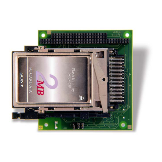
Kontron PCMCIA INTERFACES The PC/104-PCMCIA-1 comes with one dual-slot PCMCIA socket and can support PCMCIA cards of Type I to III (2x Type I/II or 1x Type III). PCMCIA cards of Type I to III all have the same planar or outline dimensions (54.00mm x 85.60mm). Card thickness also is the same within the interconnect area of each card. - Page 15 (3) The “Battery Detect 1” signal is used as “Speaker” for I/O and ATA cards. (4) The “Battery Detect 2” signal is used as “I/O Status Change” for I/O and ATA cards. (5) These signals are only used for I/O and ATA cards. PC/104-PCMCIA-1 User’s Guide PCMCIA Interfaces...
-
Page 16: Pc/104 Bus
PC/104 bus and AT ISA bus is identical between C1 - C18 and D1 - D18. The PC/104-PCMCIA-1 features both – XT bus and AT bus extension – on two, dual-row socket connector with 2.54mm x 2.54mm grid (0.1" x 0.1"). -
Page 17: Power Considerations
Kontron POWER CONSIDERATIONS The PC/104-PCMCIA-1 is a +5V-only board. PCMCIA cards used in the socket could need an additional voltage (+12V), which is not generated onboard the PC/104-PCMCIA-1. The power is supplied through power pins on the PC/104 bus connector. -
Page 18: Driver Support
This makes the difference between PCMCIA cards and other cards such as graphic-cards. Most OEMs sell software as licenses. Customers have to pay for PCMCIA drivers. The PC/104-PCMCIA-1 does not come with drivers. Drivers that might be needed for PCMCIA cards can be divided into two parts:... -
Page 19: Appendix A: Resource Allocations
I/O Addresses 10.3 The PC/104-PCMCIA-1 needs one configuration area in the I/O address space to initialize the controller. The port base address can be selected by onboard hardware jumper JP101. See the Controller Configuration section of this manual for information. The following table... -
Page 20: Appendix B: Block Diagram
Kontron APPENDIX B: BLOCK DIAGRAM Appendix B: Block Diagram PC/104-PCMCIA-1 User’s Guide...
Need help?
Do you have a question about the PC/104-PCMCIA-1 and is the answer not in the manual?
Questions and answers