Sign In
Upload
Manuals
Brands
Kontron Manuals
Computer Hardware
PEP CP321
Kontron PEP CP321 Manuals
Manuals and User Guides for Kontron PEP CP321. We have
1
Kontron PEP CP321 manual available for free PDF download: Manual
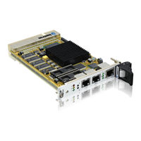
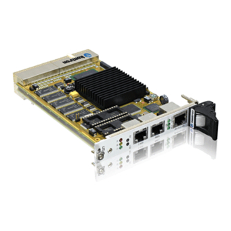
Kontron PEP CP321 Manual (144 pages)
Power PC-based CPU Board for CompactPCI Applications
Brand:
Kontron
| Category:
Computer Hardware
| Size: 0.86 MB
Table of Contents
Imprint
2
Copyright
2
Table of Contents
3
List of Tables
9
Proprietary Note
13
Trademarks
13
Explanation of Symbols
14
For Your Safety
15
High Voltage Safety Instructions
15
Special Handling and Unpacking Instructions
15
General Instructions on Usage
16
Two Year Warranty
17
1 Introduction
19
System Overview
21
Product Overview
22
Board Overview
23
Board Introduction
23
Optional Modules
25
CP320-TR1 Optoisolated RS485
25
CP320-TR2 Optoisolated RS232
25
Cp320-Io1
25
Cp-Rio3-01
25
Pmc-Hdd1
25
System Relevant Information
26
Board Diagrams
27
Functional Block Diagram
27
CP321 Functional Block Diagram
27
Frontpanels
28
CP321 Frontpanels
28
Board Layouts
29
CP321 Board (Front View)
29
CP321 Board (Reverse View)
29
Technical Specifications
30
CP321 Main Specifications
30
Applied Standards
32
CE Compliance
32
Mechanical Compliance
32
Environmental Tests
32
Related Publications
32
Compactpci Systems/Boards
32
PMC Add-On Modules/Carriers
32
2 Functional Description
33
General Information
35
Memory
37
System Memory (SDRAM)
37
Flash
37
Eeprom's
37
Memory Expansion Sockets (DIL600)
37
Board Interfaces
38
CPCI Interface and Pinout
38
Compactpci Bus Connector J1
39
Compactpci Bus Connector J2 (64-Bit Version)
40
Compactpci Bus Connector J2 (32-Bit Version)
41
Ethernet Connector and Pinout
42
Ethernet Connector Pinout
42
Ethernet Connector
42
Serial Interfaces and Pinouts
43
Serial Port Pinout
43
Serial Interface Expansion Connector and Pinout
44
PCI Expansion Connector and Pinout
44
Serial I/F Expansion Connector (CON3) Pinout
44
PCI Expansion Connector (CON11)
44
PCI Expansion Connector Pinout
45
Memory Expansion Connectors
46
DIL 32 Pinout for Various Devices
47
DIL 36 Pinout for 1 MB and 2 MB NVSRAM Devices
47
Special Board Functions
48
Watchdog Timer
48
Realtime Clock (STC M41T56)
48
Reset/Abort
48
RTC J2 Pinout
48
System Status Indicators
49
Coding Switch
49
Digital Temperature Sensor (LM75)
49
DEBUG Interface and Pinout
50
JTAG Chain Layout
50
JTAG Chain Resistor Settings
51
Options
52
3 Installation
53
Board Installation
55
Placement of the CP321
55
Front Panel I/O Connectors
56
Assembly of the CP321 and Options
56
CP321 and Options Assembly
56
Software Installation
57
4 Configuration
59
Jumper and Resistor Settings
61
J1 - Bootstrap Loader / Socket Jumper
61
J2 - Realtime Clock (RTC) Calibration Output
61
J1 - Bootstrap Loader / Socket Jumper Settings
61
Resistor Settings for Non-Standard Socket Devices
62
Board Address Map
63
CP321 Address Map
63
CP321 Upper Area Address Map
64
Board Control Registers
65
Board ID Register
65
Software Compatibility ID
65
Board ID Register
66
Software Compatibility ID
66
Memory Configuration Register
67
Flash Bank Select Register
68
SRAM Bank Select Register
68
Watchdog Control Register
69
Interrupt Enable Register
70
Control Register
71
Coding Switch Register
72
Board Logic / Revision Register
72
Event Register
73
UART Registers Address Mapping
74
Uart a
74
UART a General Register Set
74
UART a Baud Rate Register Set
74
UART a Enhanced Register Set
74
Uart B
75
UART B General Register Set
75
UART B Baud Rate Register Set
75
UART B Enhanced Register Set
75
IRQ Routing
76
Real-Time Clock
77
Register Map RTC M41T56
77
Eeprom's
78
Digital Temperature Sensor, LM75
78
5 Netbootloader
81
General Operation
83
Netbootloader Interfaces
83
MC1 (Abort) Signal
84
TERM Serial Interface
84
SER0 Serial Interface
84
Ethernet Interface
84
Netbootloader Functions
84
Netbootloader Control
85
System Status Monitoring
85
Netbootloader Control Commands
85
System Status Monitoring Commands
85
Ftp Server Access
86
FLASH Operation
86
Motorola S-Records
86
Ftp Server Commands
86
FLASH Operation Commands
86
Motorola S-Records Commands
86
Operating the Netbootloader
87
Initial Setup
87
Accessing the Netbootloader
87
Netbootloader Configuration
88
Telnet Login
89
FLASH Operations
89
Updating the Netbootloader
91
Uploading a FLASH Area
91
Plug and Play
91
Porting an Operating System to the CPU Board
92
Commands
93
CP320-IO1 Module
113
A.1. Overview
113
A.2. Board Interfaces
114
A.3. Board Layout
115
Board Layout (Front View)
115
A.4. CP320-IO1 Front Panel
116
A.5. Pinouts
117
Jn1 (CON4), 32-Bit PCI
117
Jn2 (CON5), 32-Bit PCI
117
PCI Expansion Connector (CON2/3) Pinout
118
A.6. Technical Specifications
120
CP320-IO1 Specifications
120
A.7. Board Installation
121
Installation of PMC Module
122
A.8. Jumper Setting
124
IO1 Jumper Settings for Different Module Positions
124
Cascading of IO1 (or Other) Modules Onto the CP321
124
CP320-TR1 (Optional)
127
Board Description
127
Serial Port Pinout
127
View of Underside of the CP320-TR1 Module
127
CP320-TR2 (Optional)
131
Board Description
131
View of Underside of CP320-TR2 Module
132
Post Module
133
Board Description
135
Access Addresses for CP320-Post
135
Plan and Profile Views of CP320-Post Module
136
POST Codes
137
POST Code Listing
137
PMC-HDD1 Module with Hard Disk Drive Attached
141
Pinout of the PMC Connectors
142
IDE Hard Disk Drive Connector Pinout
143
Advertisement
Advertisement
Related Products
Kontron PCI-759
Kontron PC/104-PCMCIA-1
Kontron PCI-946-1
Kontron P3S440BX
Kontron DREAMS PEED1210
Kontron PC/104-520
Kontron PCI-755
Kontron PCI-COM422
Kontron PxV414-F
Kontron PxV414-C
Kontron Categories
Computer Hardware
Motherboard
Server
Desktop
PCI Card
More Kontron Manuals
Login
Sign In
OR
Sign in with Facebook
Sign in with Google
Upload manual
Upload from disk
Upload from URL