Table of Contents
Advertisement
Quick Links
Advertisement
Table of Contents

Related Manuals for Kontron MSP8040 Series


Summary of Contents for Kontron MSP8040 Series
- Page 1 USER GUIDE MSP8040 Series Doc Rev. 1.2 [Objet ]...
- Page 2 Kontron products. This document does not entail any guarantee on the part of Kontron with respect to technical processes described in the manual or any product characteristics set out in the manual. Kontron assumes no responsibility or liability for the use of the described product(s), conveys no...
-
Page 3: Revision History
If you have any difficulties using this guide, discover an error, or just want to provide some feedback, please send a message to Kontron. Detail any errors you find. We will correct the errors or problems as soon as possible and post the revised user guide on our website. -
Page 4: Symbols
MSP8040 Series User Guide Rev. 1.2 Symbols The following symbols may be used in this manual. DANGER indicates a hazardous situation which, if not avoided, will result in death or serious injury. WARNING indicates a hazardous situation which, if not avoided, could result in death or serious injury. -
Page 5: Table Of Contents
MSP8040 Series User Guide Rev. 1.2 Table of Contents Symbols ..........................................4 Table of Contents ....................................... 5 List of Tables ........................................5 List of Figures ........................................6 List of Acronyms ......................................... 6 Electrostatic Discharge ....................................7 Limited Warranty........................................ 7 Product Description .................................... 8 1.1. -
Page 6: List Of Figures
MSP8040 Series User Guide Rev. 1.2 List of Figures Figure 1: SYMKLOUD layers .................................... 8 Figure 2: MSP804x in rear of chassis ................................9 Figure 3: MSP804x block diagram ................................10 Figure 4: MSP804x LEDs and buttons ............................... 14 Figure 5: Default IP addresses ..................................16 Figure 6: Diagram of interface paths with a management networking connection .............. -
Page 7: Electrostatic Discharge
It does not cover products which have been modified, altered or repaired by any other party than Kontron or their authorized agents. Furthermore, any product which has been, or is suspected of being damaged as a result of negligence, improper use, incorrect handling, servicing or maintenance, or which has been damaged as a result of excessive current/voltage or temperature, or which has had its serial number(s), any other markings or parts thereof altered, defaced or removed will also be excluded from this warranty. -
Page 8: 1/ Product Description
MSP8040 Series User Guide Rev. 1.2 1/ Product Description 1.1. Product Overview The MSP804x is a processor node for the MS2910 platform. Up to nine nodes can be installed in this platform, and each node has one CPU engine. MSP804x references through this guide refer to any variants of this Node Series as described in Table 2 - Node key components, unless specified otherwise. -
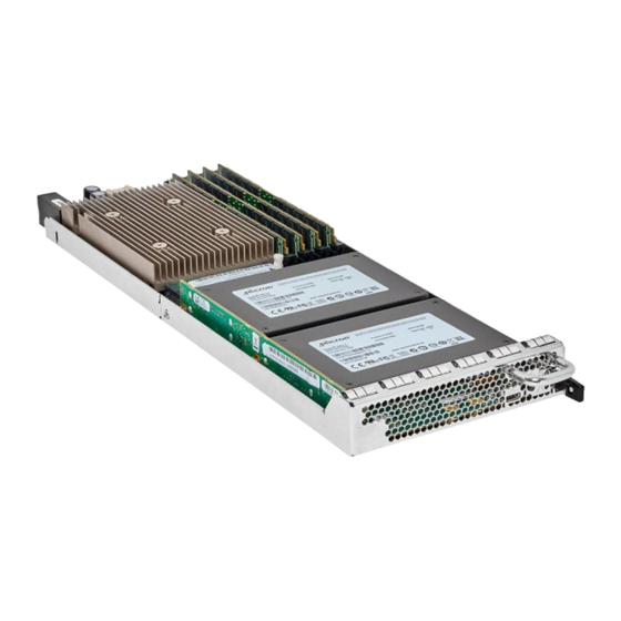
Page 9: Figure 2: Msp804X In Rear Of Chassis
MSP8040 Series User Guide Rev. 1.2 Figure 2: MSP804x in rear of chassis For information on other SYMKLOUD MS2910 components, refer to the specific component’s user manual. To obtain the latest document version or to consult other SYMKLOUD documents, visit the Kontron portal at kontron.com. -
Page 10: Block Diagram
MSP8040 Series User Guide Rev. 1.2 1.2. Block Diagram Figure 3: MSP804x block diagram www.kontron.com // 10... -
Page 11: Pci Mapping
MSP8040 Series User Guide Rev. 1.2 1.3. PCI Mapping Table 1: PCI mapping Bus:Device. Device Component Description Note Function 00:00.0 6F00 Host bridge Intel Corporation Broadwell DMI2 (rev. 01) Intel XEON D-15xx processor Intel Corporation Broadwell PCI Express Root Port 3 NVMe port 00:03.1... -
Page 12: Node Key Components
PCIe x8 add-on card plus 1x HDD/SSD 2.5” up to 15 mm high (SATA) PCIe x16 HHHL add-on card Refer to the Intel website ark.intel.com for more information on Intel components. Some of the components are optional. For more information about the PCIe option, please contact Kontron. www.kontron.com // 12... -
Page 13: Node Features
MSP8040 Series User Guide Rev. 1.2 1.5. Node Features Table 3: Node features Feature Description Remote management IPMI 2.0 (subset) KVM/virtual media Remote firmware update Comprehensive sensor network and event monitoring Hot swap Supported Refer to the user guide of the hub used in the platform for information on system... -
Page 14: Node Module Leds And Buttons
MSP8040 Series User Guide Rev. 1.2 1.6. Node Module LEDs and Buttons Figure 4: MSP804x LEDs and buttons Table 4: LED status description and button behavior MSP804x State ID (blue) Power (green) Status (amber) Identify command in progress Blinking Not affected... -
Page 15: Interfacing
MSP8040 Series User Guide Rev. 1.2 1.7. Interfacing Two types of connections can be established with node components: a networking connection and a serial console connection. Refer to the user guide of the hub used in the platform for information on how to access the SM and for the locations of the management and console ports. -
Page 16: Management Networking Connection
MSP8040 Series User Guide Rev. 1.2 1.7.1. Management Networking Connection The SYMKLOUD platform comes with a System Monitor (SM). The SM includes a web user interface and a programmatic API to access system components, including its ShMC and nodes. The IOL IP address of the component you want to connect to might be required when using certain paths. The IP address of external entities must be in the same subnet as that of the SYMKLOUD components as no default gateway is configured. -
Page 17: Figure 6: Diagram Of Interface Paths With A Management Networking Connection
Terminal emulator software such as PuTTY can be used. The Kontron ipmitool package can be downloaded from kontron.com, in the “Software Tools” section. Ensure the protocol is enabled for the interface you want to access (SSH, TELNET, etc). -
Page 18: Serial Console Connection
MSP8040 Series User Guide Rev. 1.2 Example of SOL connection to the node CPU serial console (OS): Connect to the management port with a cable or via a network. Establish an SOL connection using ipmitool: ipmitool –H <node BMC ip address>... -
Page 19: Figure 7: Diagram Of Interface Paths With A Serial Console Connection
MSP8040 Series User Guide Rev. 1.2 Figure 7: Diagram of interface paths with a serial console connection The serial port communication parameters are 115200 baud, no parity, 8 data bits and backspace key set to "Ctrl-h". BIOS POST and configuration menu redirection is VT100+. -
Page 20: Default User Names And Passwords
MSP8040 Series User Guide Rev. 1.2 1.7.3. Default User Names and Passwords Table 6: Default usernames and passwords Configuration interface Username and password SM (UI) admin admin ShMC CLI admin admin Node CPU serial console (OS) Customer specific www.kontron.com // 20... -
Page 21: 2/ Extracting And Inserting A Node Module
MSP8040 Series User Guide Rev. 1.2 2/ Extracting and Inserting a Node Module 2.1. Extracting a Node Module ESD-Sensitive Device! Take all necessary ESD protection measures. Steps in blue apply only to hot swap procedures. Press the power button of the node to be extracted. (The power button should be configured in the operating system so it performs a clean shutdown when pressed.) -
Page 22: Inserting A Node Module
MSP8040 Series User Guide Rev. 1.2 2.2. Inserting a Node Module ESD-Sensitive Device! Take all necessary ESD protection measures. Holding the handle, insert a node module. Push it in until the safety lock clicks in place. Wait for the power LED of the processor node module to become steady green (30 to 120 seconds): the node is powered on and ready to use. -
Page 23: 3/ Software Configurations And Conventions
MSP8040 Series User Guide Rev. 1.2 3/ Software Configurations and Conventions Before configuring node modules, review the following list of mandatory tasks. You can refer to that list to ensure you have performed the basic tasks required for proper system operation. Note that some of these tasks may have already been completed. -
Page 24: 4/ Configuring Node Modules
MSP8040 Series User Guide Rev. 1.2 4/ Configuring Node Modules 4.1. Node Reset To reset the CPU of a node: Node CPU serial console, IPMITOOL From the SM From the Node CPU serial console Dashboard > Monitor Send a break sequence... -
Page 25: Boot From Virtual Media
MSP8040 Series User Guide Rev. 1.2 To change the boot order of a processor node temporarily: Node CPU serial console, IPMITOOL Perform a node reset (section 4.1) Perform a node reset (section 4.1) Press [Del] or [F2] when prompted to enter the bios... -
Page 26: 5/ Performing Updates
MSP8040 Series User Guide Rev. 1.2 5/ Performing Updates A ZIP file provided by Kontron contains firmware updates for node components. 5.1. Processor Node Update To update the firmware of the node BMC, BIOS and FPGA: Not possible from a CLI-type interface Dashboard >... -
Page 27: Appendix A - Sensor List
MSP8040 Series User Guide Rev. 1.2 Appendix A – Sensor List The following tables contain information on the sensors of the MSP804x hub. Table 8 provides detailed information on the sensors described in blue in Table 7. Table 7: Sensor list... - Page 28 MSP8040 Series User Guide Rev. 1.2 Sensor Type Reading Sensor Name Description Event Offset Code Type Code Power consumption in watts Power NODE of the complete blade See IPMI v2.0 table 42-2 for (Threshold (Watt) threshold based event Power consumption in watts...
- Page 29 MSP8040 Series User Guide Rev. 1.2 Sensor Type Reading Sensor Name Description Event Offset Code Type Code Only offset 0,1 are used BMC Reboot (Digital BMC Reboot detection See IPMI v2.0 table 42-3, Sensor (Platform Alert) Discrete) type code 24h for sensor definition...
-
Page 30: Table 8: Detailed Information For Specific Sensors
MSP8040 Series User Guide Rev. 1.2 Table 8: Detailed information for specific sensors Sensor Event/Reading Sensor Specific Sensor Type Event Trigger Name type code offset Event Code Assert Trigger OEM Kontron Kontron Event Overflow Trigger IPMI Info-1 Firmware Info Firmware... - Page 31 MSP8040 Series User Guide Rev. 1.2 Sensor Event/Reading Sensor Specific Sensor Type Event Trigger Name type code offset Event Data 2: Reset Type 00h: Warm reset 01h: Cold reset 02h: Forced Cold [ Warm reset reverted to Cold ] 03h: Soft reset [ Software jump ]...
- Page 32 Kontron is a listed company. Its shares are traded in the Prime Standard segment of the Frankfurt Stock Exchange and on other exchanges under the symbol “KBC”. For more information, please visit: http://www.kontron.com/...
Need help?
Do you have a question about the MSP8040 Series and is the answer not in the manual?
Questions and answers