RGBlink VENUS X1 User Manual
Hide thumbs
Also See for VENUS X1:
- User manual (109 pages) ,
- Manual (94 pages) ,
- Quick start manual (41 pages)

Related Manuals for RGBlink VENUS X1


Summary of Contents for RGBlink VENUS X1
- Page 1 VENUS X1 User Manual Manual #: RGB-RD-UM-VENUS X1 E001 Revision: V1.3 VENUS X1 User Manual...
- Page 2 No part may be copied, reproduced or translated without permission. Notice RGBlink provides this manual ―as is‖ without warranty of any kind, either expressed or implied, including but not limited to the implied warranties or merchantability and fitness for a particular purpose. RGBlink may make improvements and/or changes to the product(s) and/or the program(s) described in this publication at any time without notice.
- Page 3 30 days after the transfer of risks. In the event of justified notice of compliant, RGBlink can repair the fault or provide a replacement at its own discretion within an appropriate period.
- Page 4 Company Address Xiamen RGBlink Science & Technology Co., Ltd. Headquarter: S603~604 Weiye Building Torch Hi-Tech Industrial Development Zone Xiamen, Fujian Province, P.R.C Shenzhen office: Floor 11, A1 Building, Baiwang R&D Building, Shahe West Road, Xili Town, Nanshan District, Shenzhen, Guangdong Province, P.R.C...
- Page 5 To avoid fire hazard, use only the fuse having identical type, voltage rating, and current rating characteristics. Refer fuse replacement to qualified service personnel. Do Not Operate in Explosive Atmospheres To avoid explosion, do not operate this product in an explosive atmosphere. VENUS X1 User Manual...
- Page 6 Highlights an essential operating procedure, condition or statement. CAUTION The exclamation point within an equilateral triangle is intended to alert the user to the presence of important operating and maintenance (servicing) instructions in the literature accompanying the appliance. VENUS X1 User Manual...
- Page 7 2. Update the menu tree. 3. Update the product picture. 4. Update the dimensions drawing 5. Update the specification. 6. Update ―Optional Module Installation and Replacement Instruction‖. 7. Add ―VENUS X1 Connect APP Control Operation‖. V1.3 2016-05-05 0003# 1. Update the product picture. Vira 2.
-
Page 8: Table Of Contents
System Overview ..................23 Application Questions .................. 24 2. Hardware Orientation ..............25 In This Chapter .................... 25 VENUS X1 Back Panel ................... 26 CONT Interface ...................... 26 4: DIP Switch ......................26 5: 10/100M UDP Interface ..................26 6: USB Interface ....................26 7: RS232 Interface .................... - Page 9 Illuminated Power Switch and Power ..............30 9. 18: Power Interface and Illuminated Power Switch ......... 30 Interface Protection Block ..................31 VENUS X1 Front Panel ................. 32 OLED Panel ......................34 Menu Button ......................34 Signal Buttons ....................... 34 Function ........................
- Page 10 SAVE FUNCTION ..................63 LOAD FUNCTION ..................64 PIP FUNCTION ..................... 64 SPLIT FUNCTION ..................65 SCALE FUNCTION ..................66 5. Communication Software Guideline ..........67 In This Chapter .................... 67 Software Installation ..................68 Software Operation ..................72 VENUS X1 User Manual...
- Page 11 Display Toolbar ...................... 78 Output Toolbar ...................... 78 Images Display Toolbar ..................79 User Mode Toolbar ....................79 Log Toolbar......................79 Information Toolbar ....................80 Control ........................80 Language ....................... 84 Admin ........................84 Help ........................85 VENUS X1 User Manual...
- Page 12 User Define the SCALE Key................. 123 Using TAKE Mode ..................125 Special Effects Switching ................126 Set the Audio ..................... 127 Using Black Out ..................128 LAN Remote Control Setting ..............129 Save the Parameter ................... 132 VENUS X1 User Manual...
- Page 13 Set Auto Adjust for VGA Input ................137 HDMI, DVI Input Offset or cannot be Full Size Shown ........ 138 Manual Adjust the HDMI, DVI and EXT HDMI, EXT DVI ........138 Software Upgrade Failed ................138 VENUS X1 User Manual...
- Page 14 Failed when Upgrade Less than 100% ..............138 A. Specification ................. 139 B. Contact Information ..............146 C. Software Upgrade ................. 147 D. Optional Module Installation and ..........149 Replacement Instruction ..............149 E. VENUS X1 Connect APP Control Operation ........155 VENUS X1 User Manual...
-
Page 15: Introduction
Introduction This chapter is designed to introduce you to the VENUS X1 User Manual. Areas to be covered are: Chapter Structure How to Use This Manual Terms and Definitions System Overview Application Questions VENUS X1... -
Page 16: Chapter Structure
1. Introduction Chapter Structure Chapter Structure The following chapters provide instructions for all aspects of VENUS X1 operations. Chapter 1 Introduction Chapter 2 Hardware Orientation Chapter 3 Hardware Installation Chapter 4 Menu Orientation Chapter 5 Communication Software Guideline Chapter 6... -
Page 17: How To Use This Manual
For system setup and operations, refer to Chapter 6, ―System Setup and Operations‖ on page 96. Should you have any questions regarding the installation or operation of VENUS X1, please consult with the factory. Refer to Appendix B, ―Contact information‖ on page 146. VENUS X1... -
Page 18: Terms And Definitions
This serves as a color synchronizing signal to establish a frequency and phase reference for the chroma signal. Color burst is 3.58 MHz for NTSC and VENUS X1 User Manual... - Page 19 8 channels of audio, and control signals, over a single cable. HDMI is the de facto standard for HDTV displays, Blu-ray Disc players, and other HDTV electronics. VENUS X1 User Manual...
- Page 20 VCR, or computer. Other forms of PIP displays include image-by-image (PBP) and image-with-image (PWP), which are commonly used with 16:9 aspect display devices. PBP and PWP image formats require a separate VENUS X1 User Manual...
- Page 21 “SMPTE”: Society of Motion image and Television Engineers. A global organization, based in the United States, that sets standards for baseband visual communications. This includes film as well as video and television standards. “TCP/IP”: Transmission Control Protocol/Internet Protocol. The VENUS X1 User Manual...
- Page 22 8514/A card (35.5 kHz, 86 Hz) in mode 4. It has a pixel by line resolution of 640×480 with a color palette of 16 bits and 256,000 colors. “YPbPr”: Used to describe the color space for progressive-scan (non-interlaced) component video. VENUS X1 User Manual...
-
Page 23: System Overview
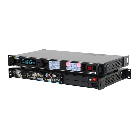
1. Introduction System Overview System Overview VENUS X1 is a multiple outputs video processor that accepts a wide variety of video signals, including DVI, VGA, HDMI, CVBS, DP, SDI (SD/HD/3G compatible) and USB. VENUS X1 combines truly seamless, fade in fade out, glitch-free switching with advanced scaling technologies to meet the requirements of high quality, high resolution video presentations. -
Page 24: Application Questions
1. Introduction Application Question Application Questions RGBlink offers solutions to demanding technical problems. Any application questions, or required further information, please contact with our Customer Support Engineers. Refer to Appendix B for contact details. VENUS X1 User Manual... -
Page 25: Hardware Orientation
Hardware Orientation In This Chapter This chapter provides detailed information about the VENUS X1 hardware. The following topics are discussed: VENUS X1 Back Panel VENUS X1 Front Panel VENUS X1 User Manual... -
Page 26: Venus X1 Back Panel
2. Hardware Orientation VENUS X1 Back Panel VENUS X1 Back Panel The figure below illustrates the professional interface and control signals of VENUS X1 back panel. INTERFACE INTERFACE 1. 2. 3 CVBS Input BNC Optional Module Slots DIP Switch VGA Input DB15... -
Page 27: 7: Rs232 Interface
2. Hardware Orientation VENUS X1 Back Panel 7: RS232 Interface Used to connect the windows control program or device upgrade. INPUT Interface It includes 1 HDMI input by HDMI-A interface, 1 CVBS inputs by BNC interface, 1 VGA input by DB15 interface, and 1 DVI input by DVI-I interface, which can be compatible with HDMI. -
Page 28: 15: Dvi2 Output
DVI1 output, connect to the monitor or LED screen which has DVI interface (This connector can not support hot-plugging). DVI loop out, connect to the DVI input of the next VENUS X1 or the device with DVI input. System default DVI1 port. If do split via DVI LOOP port, it needs to select ―DVI LOOP‖... - Page 29 (This connector does not support hot-plugging). DVI Input (DL Optional Module): Input the video signal from computer, DVI signal generator. Connect to the same DVI interface on VENUS X1. DVI Loop Out (DL Optional Module): Connect to the DVI input of the next VENUS X1 or the device with DVI input.
-
Page 30: Illuminated Power Switch And Power
2. Hardware Orientation VENUS X1 Back Panel Illuminated Power Switch and Power 9. 18: Power Interface and Illuminated Power Switch AC 85-264V 50/60Hz IEC-3 Power Interface. For more details about the input/output numbers, supported resolutions, signal level, format standard, etc, please refer to Specification part. -
Page 31: Interface Protection Block
2. Hardware Orientation VENUS X1 Back Panel Interface Protection Block VENUS X1 equips the interface protection blocks on both sides of the back panel, the purpose are as follows: 1. Protect the interfaces, it avoids the interface damage that may caused if the back panel hits the ground. -
Page 32: Venus X1 Front Panel
Plug in the power cord and push power to ON position. OLED module on the front panel will show RGBlink and go into its self verification before it load last setting config and send processed image to the target monitor. - Page 33 2. Hardware Orientation VENUS X1 Front Panel Note: INPUT DVI: NO INPUT--System default DVI signal, there is no input or the DVI signal is invalid. IP ADDRESS--The IP address is 192.168.0.100. : Recall Save 1. : Enable the network function.
-
Page 34: Oled Panel
2. Hardware Orientation VENUS X1 Front Panel VENUS X1 front panel as following: OLED Panel Used to show button menu and menus for interactive communication. Menu Button Used to adjust menu on OLED and for information interaction. Push the rotary button to confirm current options. -
Page 35: Function
2. Hardware Orientation VENUS X1 Front Panel Optional module input selection button 8, push the button, its LED light turns on, output will be switched to this channel. Support signals include: SDI, VGA, DVI, DP, CVBS, USB and HDMI. Optional module input selection button 9, push the button, its LED light turns on, output will be switched to this channel. - Page 36 Set up the PIP. Note VENUS X1 V1.3 can not support DSK function button. Screen parameters setting button. Push the button, its LED light turns on, user can choose full size or screen size, and set the size and position of the screen.
- Page 37 Save button: Push the button to enter SAVE mode, turn the knob or push the number button which light up to save. VENUS X1 supports 36 saving modes, and the button 1, 2, 3, 4, 5, 6, 7, 8, 9, 0 means SAVE1~10.
- Page 38 2. Hardware Orientation VENUS X1 Front Panel The OLED menu will show finish after finish loading. For details, please refer to LOAD Function Load Saved Settings. Advanced menu button: Push the button to enter the menu items. Turn the knob to select the relevant submenu. For details, please refer to MENU menu orientation.
-
Page 39: Hardware Installation
Hardware Installation In This Chapter This chapter provides comprehensive installation instruction for VENUS X1 hardware: Following is the mechanic info of VENUS X1 for your reference. VENUS X1 User Manual... -
Page 40: Safety Precautions
If there is damage, notify the shipping carrier immediately for all claims adjustments. Site Preparation The environment in which you install your VENUS X1 should be clean, properly lit, free from static, and have adequate power, ventilation, and space for all components. -
Page 41: Menu Orientation
Menu Orientation In This Chapter This chapter describes all VENUS X1 processor menus, including how they are accessed, the functions that are available, and descriptions of each menu tree (in block diagram format). The following topics are discussed: • MENU ... -
Page 42: Menu
Push the MENU to menu items, menu as shown: Turn the knob to select menu items. -> before the menu means it’s in selected state. Push the knob to enter corresponding setting or view the menu. VENUS X1 User Manual... -
Page 43: Input
Push the [MENU] button, OLED display menu, push the knob to select <INPUT>, show menus as follows: INPUT DETAIL: Show the current input source and input format. ZOOM: It can adjust the image zoom size and positions, settings including as follows: VENUS X1 User Manual... - Page 44 ADC AUTO ADJUST: Mainly for brightness auto adjusting. HDMI/EXT ADJUST: When HDMI or optional module input signal image shift, please adjust image’s H POS and V POS to display in full screen image. Sub menu as follows: VENUS X1 User Manual...
- Page 45 V POS: Image vertical position. RESET: If image quality distorts by improper operation, it can be recover by reset. EDID MANAGE: Choose the detination port and source file, VENUS X1 supports the EDID manage ports and types are as follows: Supported EDID...
-
Page 46: Output
SCREEN FOLLOW SCALE: User can enable or disable this function. When choose ―ON‖, the size of the screen will change according to scale setting. RESET: If image quality distorts by improper operation, it can be recover by reset. VENUS X1 User Manual... - Page 47 RESET: If image quality distorts by improper operation, it can be recover by reset. DVI2, the settings include DVI MODE, BIT DEPTH, DATA RANGE, DE ADJUST and RESET, the settings are same with DVI1. ASPECT RATIO: Aspect ratio setting, user can choose 4:3, 16:9 and DEFAULT. VENUS X1 User Manual...
-
Page 48: Picture
Others comments to do these operations. If image distorted by improper operation, it can be initialized operated to recover by factory reset. VENUS X1 User Manual... - Page 49 It should combined with "AND/OR" conditions when judging. BELOW: In image 2, if the pixel value is lower than the setting value, then VENUS X1 User Manual...
- Page 50 LAYOUT: There are 7 PIP layouts, can choose PIP layouts anyone, the corresponding results are as follows. PIP L+T PBP L+R PBP T+B SELECT: Can choose to set the size or position of IMAGE A or IMAGE B VENUS X1 User Manual...
-
Page 51: Split
V SIZE: The height of the device when do split. ADVANCE: H SIZE, V SIZE, H POS and V POS setting. If image quality distorts by improper operation, it can be recover by reset. NORMAL SPLIT: For normal split, user should enable the split function, VENUS X1 User Manual... -
Page 52: Transition
DEINTERLACE: Force Deinterlace function, can choose ―ON‖ or ―OFF‖. ON: Force deinterlace. OFF: No deinterlace. IMAGE ENHANCE: Image enhancement function, used for image edge sharpening, color reduction and image scaling. MODE: Special effects switching mode. DISSOLVE: Fade in fade out effects switching. VENUS X1 User Manual... - Page 53 WIPE TOP LIEFT OUT: WIPE TOP RIGHT IN: WIPE TOP RIGHT OUT: WIPE BOTTOM LEFT IN: WIPE BOTTOM LEFT OUT: WIPE BOTTOM RIGHT IN: WIPE BOTTOM LEFT OUT: WIPE LEFT IN: WIPE LEFT OUT: WIPE RIGHT IN: VENUS X1 User Manual...
-
Page 54: Scale
User can also push the [MENU] button two times to set up the TRANSITION. SCALE Push the [MENU] button to go into the menu items, turn the knob button to select <SCALE>, show menus as follows: H SIZE: Width setting. V SIZE: Height setting. VENUS X1 User Manual... -
Page 55: Save Setup
Push the [MENU] button to go into the menu items, turn the knob button to select <SAVE SETUP>, show menus as follows: SAVE TO: VENUS X1 provides 36 save modes, users can save the current operation to SAVE1 to SAVE36. -
Page 56: System
HOT BACKUP: User can enable or disable the hot backup function. Choose ―ON‖ to set the backup signal for BACKUP_1 to BACKUP_5. It will VENUS X1 User Manual... - Page 57 LED display. For more details, please refer to: User Define the SCALE Key. OLED LUMINANCE: Set the OLED luminance, the adjustment range is 1~15. FAN CONTROL: User can enable or disable the auto speed function, set VENUS X1 User Manual...
-
Page 58: Led Management
QUICK CONNECTION: Including the following settings: SENDING CARD TYPE: VENUS X1 V1.3 supports three kinds of sending card, LINSN TS 802, NOVA STAR MSD 300 and COLORLIGHT T7. SENDING CARD NO.: User can choose No.1 or No.2 sending card. - Page 59 X: Set the start point X. Y: Set the start point Y. SEND TO RECEIVER: Send to receiver after setting. COLOR TEMP: User can set color red, color green, color blue, and save to sender card. VENUS X1 User Manual...
-
Page 60: Language
FACTORY RESET Enter FACTORY RESET to reset or reset the IP, choose YES and push the knob to confirm, then VENUS X1 is reset to its factory settings. After 5 seconds, it completes factory settings and is ready for more operations. -
Page 61: Quick Menu
ON: Force deinterlace. OFF: No deinterlace. IMAGE ENHANCE: Image enhancement function, used for image edge sharpening, color reduction and image scaling. MODE: Special effects switching mode. DISSOLVE: Fade in fade out effects switching. CUT: Fast switching. VENUS X1 User Manual... - Page 62 WIPE TOP RIGHT IN: WIPE TOP RIGHT OUT: WIPE BOTTOM LEFT IN: WIPE BOTTOM LEFT OUT: WIPE BOTTOM RIGHT IN: WIPE BOTTOM LEFT OUT: WIPE LEFT IN: WIPE LEFT OUT: WIPE RIGHT IN: WIPE RIGHT OUT: VENUS X1 User Manual...
-
Page 63: Save Function
Push the [SAVE/1] button, the button led light turn on, and enter the save function menu. OLED module show as follows: SAVE TO —>SAVE 1 Button is on can be saved Button flashes will be overwrite User can operate according to the OLED module information. VENUS X1 User Manual... -
Page 64: Load Function
LAYOUT: There are 7 PIP layouts, Can choose PIP layouts anyone, the corresponding results are as follows. PIP L+T PBP L+R PBP T+B SELECT: Can choose to set the size or position of IMAGE A or IMAGE B individually. VENUS X1 User Manual... -
Page 65: Split Function
NORMAL SPLIT: For normal split, user should enable the split function, that is, turn the knob, and set the <SPLIT> as ―ON‖, push the knob to confirm. System default ―OFF‖. User can set the normal split in the sub VENUS X1 User Manual... -
Page 66: Scale Function
V POS: Vertical phase setting. RESET: If image quality distorts by improper operation, it can be recover by reset. For details, please refer to the instructions in the manual: Set the Size and Position of Single Image. VENUS X1 User Manual... -
Page 67: Communication Software Guideline
The following topics are discussed: Software Installation Software Operation How to Connect Windows Control Program by RS232 Interface How to Connect Windows Control Program by USB Interface How to Connect Windows Control Program LAN Interface VENUS X1 User Manual... -
Page 68: Software Installation
5. Communication Software Guideline Software Installation Software Installation VENUS X1 video processor is configured with user friendly communication software, support drag and drop operation for edit and display. Also it can be customized with schedule function. Double click to install, English version default for use, click ―Next‖... - Page 69 5. Communication Software Guideline Software Installation User can select ―Change‖ to choose the VENUS X1 install software: VENUS X1 User Manual...
- Page 70 5. Communication Software Guideline Software Installation Click ―Next‖ to go on: Click ―Next‖ to go on: VENUS X1 User Manual...
- Page 71 5. Communication Software Guideline Software Installation Click ―Next‖ to go on: Click ―Finish‖ and ready to run VENUS X1 console. VENUS X1 User Manual...
-
Page 72: Software Operation
VENUS X1 communication software interface as shown: Connection Besides the power cord, the product default equip with the RS-232 cable, DB9F cable, and RJ11 (6 B4C) cable to connect VENUS X1 to the windows control program. For more detailed information, please refer to: ―How to Connect Windows... -
Page 73: Use
If successful connect, the icon becomes , status on the left button showing File Toolbar : Open script. User can open saved script and alter its parameters. VENUS X1 User Manual... -
Page 74: Communication Toolbar
: Save script. Save current user parameters as script to the prescribed path. Communication Toolbar : Open COM. : Close COM. : Set COM. Device Toolbar : Synchronization. : Save to flash. : Load form flash. VENUS X1 User Manual... - Page 75 5. Communication Software Guideline Software Operation : Factory setup. Schedule Toolbar : Customize schedule. : Execute schedule. Execute tasks according to schedule. VENUS X1 User Manual...
-
Page 76: Output Resolution Toolbar
5. Communication Software Guideline Software Operation Output Resolution Toolbar User can choose different output resolution by selecting from pull down list. VENUS X1 has 22 output resolutions for users selection. Note Same as MENU OUTPUT STANDARD Display Mode Toolbar Choose to work in one window or two window. -
Page 77: Signal Input Toolbar
User can set size and position of the screen, mainly applies to LED screens users. After setting screen parameter, in PIP or PBP mode, the image will display on corresponding screen. Note Same as MENU OUTPUT SCREEN PARAMETERS VENUS X1 User Manual... -
Page 78: Image Toolbar
Generally, it is not recommend to set the gamma, since LED screen itself has Gamma function. For further information, users can contact with our customer service. Output Toolbar User can customize the brightness and the contrast. VENUS X1 User Manual... -
Page 79: Images Display Toolbar
This process is sync to the parameters in image toolbars. User Mode Toolbar Users can recall the saved user mode1, mode2 or mode3. Log Toolbar User can save or delete the operate log file. VENUS X1 User Manual... -
Page 80: Information Toolbar
5. Communication Software Guideline Software Operation Information Toolbar It is the VENUS X1 connect state, device name, software version and serial number. Control Synchronization: Read the current parameters of VENUS X1. Device IP: Users can set equipment IP, mask and gateway, usually used in one computer control or remote control several computers. - Page 81 Choose the output port and set the output mode, data range, bit depth and EDID Manage: Choose the EDID date source and input port. VENUS X1 supports the EDID manage ports and types are as follows: VENUS X1 User Manual...
- Page 82 FOLLOW, CUSTOM Audio: User can enable or disable the audio function. If choose ―ON‖, user can set the volume, mode, DVI and DP. Graphic Overlay: Choose the preset mode, blend mode, and set the alpha and color. VENUS X1 User Manual...
- Page 83 Users can set or adjust lower computer time through ‖Clock‖. Device Schedule: Users can set up VENUS X1 to play the appointed input video automatically in time and operation of one window or two windows, and scale the size and position.
-
Page 84: Language
Click ―Factory Setup‖, previously saved user mode will be cleared. Language This software supports both Chinese and English, user can switch the language by ―Language‖ option. Admin Advance Debug: User should input the password in the ―Admin VENUS X1 User Manual... -
Page 85: Help
Password‖ dialog for advance debug: Note Advance is only done by engineer. If need, please connect us for password. Help Version Explain: Show the content of software update history. About: Show software version and company information. VENUS X1 User Manual... -
Page 86: How To Connect Window Control Program By Rs232 Interface
Take out the RS 232 cable as following(RS-232, with 9-pin on one end, RJ 11 on the other side). Connect one side of the RJ11 download line to the RS232 on the video processor VENUS X1, and the other side to be connected to the serial port on the PC. - Page 87 Click [Device Manager] ―+‖ on the left, check the COM number, as following, COM1 is offered. Remember the COM you are using and then run the control software, find [Communication] option. In default, first time user have to click button, as following: VENUS X1 User Manual...
- Page 88 5. Communication Software Guideline How to Connect Windows Control Program by RS232 Interface Check and tap [Serial], Serial Port , for example, is COM6 which is checked from device manager. Set VENUS X1 Boud Rate to be :115200, Click [Confirm] after setting. Click [open serial], check if [COM] icon is on the bottom right corner,when there is the prompt green...
-
Page 89: How To Connect Windows Control Program By Usb Interface
Connect the USB cable to the PC and the video processor. Turn on the VENUS X1, for the first time to use USB, the PC will remind finding the new hardware and ask to install the driver for this new driver: Install from the list or specified location, click ―NEXT‖:... - Page 90 5. Communication Software Control Guide How to Connect Window Control Program by USB Interface When the installation finish, can go to check the installed COM port inside the device management, as following image shows: VENUS X1 User Manual...
- Page 91 How to Connect Window Control Program by USB Interface Install the console software, and run after install, shows the interface of the console as following: Select the COM as installed just now, and set the VENUS X1 Boud Rate to be: 115200. VENUS X1...
- Page 92 VENUS X1. VENUS X1 User Manual...
-
Page 93: How To Connect Windows Control Program By Lan Interface
First, install the windows control software to the control computer; Connect VENUS X1 and computer with cable, the connection diagram is as follow: Power on VENUS X1 and start the network function, specific steps as below: The first step: push MENU button, login MENU—SYSTEM—ETHERNET,... - Page 94 If computer IP address and equipment IP address are not in same band, For example, the computer IP address is 218.032.010.201. We need to revise the computer IP address to 192.168.0.xxx. Open network connections, right click on VENUS X1 User Manual...
- Page 95 Input equipment IP address, click [OK]. Click to open the serial port, if the [Comm] button (in the lower-right corner of the control software interface) is green, and log outputs information smoothly, then you would control the device through PC software. VENUS X1 User Manual...
-
Page 96: System Setup And Operations
User Define the BLACK Key User Define the SCALE Key Using TAKE Mode Special Effects Switching Set the Audio Using Black Out LAN Remote Control Setting Save the Parameter Load Saved Setting VENUS X1 User Manual... -
Page 97: Single Image Switching
VGA signal is effective and stable. And if the VGA signal is invalid or no input, VGA button light will flash. The same method can switch the signals among CVBS, HDMI and optional input signal. VENUS X1 User Manual... -
Page 98: Pip Setting
ALPHA: Can set the image transparency, the regulating range is 0 to 16. SELECT: Can choose to set the size or position of IMAGE A or IMAGE B individually. Note User can also push [SPLIT] function reuse key to select IMAGE A or IMAGE B. VENUS X1 User Manual... -
Page 99: Set Led Display Connection
Set LED Display Connection Set LED Display Connection VENUS X1 can realize three connection as follows connecting the Port D or Port U of one sending card to LED screen, connecting the both Port D and Port U of one sending card to LED screen, connecting the Port D and Port U of two sending cards to LED screen (PORT A or PORT B is for Colorlight, and PORT D or PORT U is for Linsn). - Page 100 (8) Turn the knob, choose <RECEIVING CARD SET>, push the knob to confirm. Turn the knob again, and choose <CHOOSE CABLE>, push the knob to confirm. Turn the knob, choose PORT U1 and push the knob to confirm. SENDING CARD SET >> ->RECEIVING CARD SET >> VENUS X1 User Manual...
- Page 101 Offset (A/B) Y >> CONNECT CARD TYPE After setting, turn the knob and choose <CONNECT CARD TYPE> according to actual connection mode. VENUS X1 support 8 kinds of connection modes, they are respectively. HEIGHT Offset (A/B) X Offset (A/B) Y ->CONNECT CARD TYPE...
- Page 102 Push the knob to confirm, turn the knob, select <SENDING CARD TYPE> in <QUICK CONNECTION> option, push the knob to confirm, turn the knob, select the sending card type, for example, select Linsn (VENUS X1 supports Linsn and Colorlight sender card, for Nova sender card, it only support brightness and Gamma adjustment).
- Page 103 Turn the knob, choose <RECEIVING CARD SET>, push the knob to confirm. Turn the knob again, and choose <CHOOSE CABLE>, push the knob to confirm. Turn the knob, choose PORT D1 and push the knob to confirm. VENUS X1 User Manual...
- Page 104 ->CONNECT CARD TYPE >> Choose the connection mode, the setting is same as Port U1. Then connection of both the Port D and Port U of One Sending Card to LED Screen is finished. Rendering is as follows: VENUS X1 User Manual...
- Page 105 Turn the knob, choose No.2, push the knob to confirm. Shown as follows: ->QUICK CONNECTION >> ADVANCED >> SENDING CARD TYPE LINSN ->SENDING CARD NO. No.2 OUTPUT FORMAT >> QUICK CONNECTION >> VENUS X1 User Manual...
- Page 106 (10) Push the [MENU] to return the previous menu, choose <SENDING CARD SET>, push the knob to confirm, and enter to the next level menu, shown as follows: ->SENDING CARD SET >> RECEIVING CARD SET >> VENUS X1 User Manual...
- Page 107 (12) Same as above, set X of Port D of No.2 sending card as 360. Then connect the Port D and Port U of Two Sending Cards to LED Screen is finished. Rendering is as follows: VENUS X1 User Manual...
- Page 108 6. System Setup and Operation Set LED Display Connection VENUS X1 User Manual...
- Page 109 6. System Setup and Operation Set LED Display Connection VENUS X1 User Manual...
-
Page 110: Split Setting
VENUS X1. User can also do cascade via DVI LOOP port, and it needs to select ―DVI LOOP‖... - Page 111 ADVANCE: H SIZE, V SIZE, H POS and V POS setting. If image quality distorts by improper operation, it can be recover by reset. RESET: If image quality distorts by improper operation, it can be recover by reset. VENUS X1 User Manual...
-
Page 112: Set The Size And Position Of Single Image
V SIZE: Height setting. H/V SIZE: Width and height equal proportion scale setting. H POS: Horizontal phase setting. V POS: Vertical phase setting. RESET: If image quality distorts by improper operation, it can be recover by reset. VENUS X1 User Manual... -
Page 113: Choose And Custom Output Resolution
After the digital, push Knob will add *, means before the * is the horizontal size. Same operation for vertical size, for example input1536 as following: CUSTOMIZED: *1536×1536@ After the digital, push the knob will add @, means before the @ is the VENUS X1 User Manual... - Page 114 Use the digital buttons to finish the settings, For example, input refresh rate 60. CUSTOMIZED: *1536×1536@60 After input all the values, push knob to enable VENUS X1 to output this resolution. VENUS X1 will take 5~10 seconds to enable this output resolution. Note All the resolution inside the value 2048 x 1152 x 60 = 141557760 can support.
-
Page 115: Screen Size Setting
Screen Size Setting Screen Size Setting VENUS X1 supports the screen parameters to meet the requirement where user want to switch between scale screen size and full display size (like monitor). This is only enable for a single display window. Following is an example of a screen size is1408 x 832. - Page 116 6. System Setup and Operation Screen Size Setting VENUS X1 User Manual...
-
Page 117: Zoom The Image
H RIGHT--Zoom in horizontal and the image will be zoom in to the right direction from its left. H LIFT/RIGHT--Zoom in horizontal but in both left and right direction from its middle. CENTER--Zoom in 4 corner direction from center. VENUS X1 User Manual... -
Page 118: Text Overlay Setting
4. Make sure VGA input is IMAGE B, and DVI input is IMAGE A, if not, choose <SWAP WINDOW> option by push [PIP/DSK] button, and choose ―ON‖ for <SWAP WINDOW>. LAYOUT PIP L+T SELECT IMAGE A ->SWAP WINDOW 关 VENUS X1 User Manual... - Page 119 <BLEND MODE> or <BLEND LEVEL> to get a better effect. TEXT OVERLAY ->PRESET WhOnBk2 BLEND MODE MODE1 BLEND LEVEL 7. Push the [SAVE/1] button to save the above parameters. VENUS X1 User Manual...
-
Page 120: User Define The Black Key
3. Push the knob to confirm, turn the knob, and choose <BLACK KEY>: ->BLACK KEY BLACK SCALE KEY SCALE 4. Push the knob to confirm, turn the knob, and choose <FREEZE>, <TEST PATTERN> or <BRIGHT>, push the knob to confirm. VENUS X1 User Manual... - Page 121 AUTO SWITCH There are 66 kinds of test patterns. If choose <AUTO SWITCH>, VENUS X1 will output all the test patterns one by one, and the interval between is 1 to10S. Push the button again, its LED light is off, and output the video image.
- Page 122 If image quality distorts by improper operation, it can be recover by reset. ->BRIGHTNESS CONTRAST SATURATION SHARPNESS ->COLOR RED COLOR GREEN COLOR BLUE GAMMA LINEAR ->RESET VENUS X1 User Manual...
-
Page 123: User Define The Scale Key
3. Push the knob to confirm, turn the knob, and choose <SCALE KEY>: BLACK KEY BLACK ->SCALE KEY SCALE 4. Push the knob to confirm, turn the knob, and choose <TAKE>, push the knob to confirm. BLACK KEY BLACK ->SCALE KEY TAKE VENUS X1 User Manual... - Page 124 6. System Setup and Operation User Define the SCALE Key 5. After define SCALE KEY as TAKE, the SCALE button will light up. VENUS X1 User Manual...
-
Page 125: Using Take Mode
TAKE source you have selected. 4. After choose the signal, push the [SCALE] ([TAKE]) button, and the signal will be taken to the output. VENUS X1 User Manual... -
Page 126: Special Effects Switching
FADE TIME: Switch time setting. Turn the knob to choose the time and push the knob to confirm. The switching time ranges from 0 to 3S. ALPHA: It can set the image transparency, the regulating range is among 0 to 16. VENUS X1 User Manual... -
Page 127: Set The Audio
2 and input audio 3. Input audio 2 can choose any input except the inputs of input audio 1 and input audio 3. Input audio 3 can choose any input except the inputs of input audio 1 and input audio 2. VENUS X1 User Manual... -
Page 128: Using Black Out
Black out descriptions: Black signal realizes one-key-touch to a black screen. VENUS X1 provides black effect processing for output with cut black effect. Operation is as below: Push the [BLACK/0] button, then output will cut to BLACK, shown as below:... -
Page 129: Lan Remote Control Setting
No limitation for router’s model and brand, such as VPN router model: Netcore 255 or 266; Volans VE 760W or 982W). ③One VENUS X1 processor (as long as the router’s network ports can connect to, user can place multi pieces of VENUS X1). - Page 130 If router’s default network segment is 192.168.0.1, then it is same to processor IP address segment, open up windows control software and user can directly control on VENUS X1. If router’s default network segment is 192.168.1.1, then user need to change router’s default gateway or change processor’s IP, both methods are available, but we suggest to...
- Page 131 Go to router setting part and find out ―LAN port setting‖, change the default value ―192.168.1.1‖ to be ―192.168.0.1‖. Save the setting and restart the router, then user can directly control on VENUS X1 via windows control software. VENUS X1...
-
Page 132: Save The Parameter
6. System Setup and Operation Save the Parameter Save the Parameter VENUS X1 provides 36 save preferences, operations are as follows: 1. Push the [SAVE/1] button, the button light is on, and enable the SAVE function. SAVE TO ->SAVE 1... -
Page 133: Load Saved Setting
6. System Setup and Operation Load Saved Setting Load Saved Setting VENUS X1 provides 36 save preferences, operations are as follows: 1. Push the [LOAD/6] button, the button light is on, and enable the LOAD function. RECALL SAVE ->SAVE 1... -
Page 134: Common Questions And Solutions
APP Software cannot Properly Connected in Mobile Phone or Tablet Computer VGA Input Offset or can't be Full Size Shown HDMI, DVI Input Offset or cannot be Full Size Shown Software Upgrade Failed VENUS X1 User Manual... -
Page 135: Input Jitter For I System Of Hdmi
Input Jitter for I System of HDMI Change the Input as P System Some HDMI input of VENUS X1 will jitter for the I system of HDMI, please change the input as P system. Connect the HDMI Signal to the EXT_HDMI Input If user can’t change the input format as P system, please connect the I... -
Page 136: There Is Flash Point When Output To The Led Screen
The DVI output port is loose or oxidation due to plug and pull frequently or long time no use, which may cause the signal attenuation. There are two DVI output ports on VENUS X1, please change to the other DVI output port and test again. -
Page 137: App Software Cannot Properly Connected In Mobile Phone Or Tablet
<INPUT>, turn the knob and choose <VGA ADJUST>, push the knob to confirm. Turn the knob and choose <AUTO ADJUST>, the auto adjust time is about 10 seconds. If auto adjust cannot solve the problem, please manually adjust in <VGA ADJUST>. VENUS X1 User Manual... -
Page 138: Hdmi, Dvi Input Offset Or Cannot Be Full Size Shown
PC and try to update again. Failed when Upgrade Less than 100% Write the 100M BOOT program in the program folder, after write successfully, write the 100M MCU program, and upgrade the complete program package finally. VENUS X1 User Manual... -
Page 139: Specification
Supported 1080P50/59.94/60 I 1080i50/59.94/60 Resolution 720p50/59.94/60 VESA:800×600@60 I 1024×768@60 I 1280×768@60 I 1280×1024@60 I 1600×1200@60 I 1920×1080@60 Signal Level TMDS pwl,single pixel input,165MHz bandwidth Format Standard HDMI 1.3 DVI Loop Out (Standard) Number of Loop Out VENUS X1 User Manual... - Page 140 1600×1200@60 I 1680×1050@60 I 1920×1080@60 I 1920×1080@50 I 1920×1200@60 I 2048×1152@60 I 2560×812@60 I 2560×816@60 I 1536×1536@60 R、G、B、Hsync、Vsync:0 to1Vpp±3dB (0.7V Video+0.3v Signal Level Sync ) 75 ohm black level: 300mV Sync-tip: 0V 3G-SDI Input (SDI optional module) VENUS X1 User Manual...
- Page 141 Resolution SMPTE 125M (SD): 1440×487/60 (2:1), 525-line 487 generic SMPTE ITU-R BT.656 (SD): 1440×576/50 (2:1), 625-line generic. Belden 1694A cable: 150m at 2.97Gb/s Balance 250m at 1.485Gb/s 480m at 270Mb/s DVI IN+DVI LOOP (DL optional module) VENUS X1 User Manual...
- Page 142 Support resolution: WQXGA + (1920 x 1200), and color Resolution depth: 30/36 bit (each primary 10/12 bit) Supported 10.8Gb/s Bandwidth Format Standard DP1.0 HDMI IN+HDMI LOOP (HL optional module) Interface Appearance 52(L)×19.5(W)(mm) Board Size HDMI Input VENUS X1 User Manual...
- Page 143 TMDS pwl, single pixel input,165MHz bandwidth Format Standard HDMI 1.3 CVBS Input (CVBS optional module) Interface Appearance 52(L)×19.5(W)(mm) Board Size Number of Inputs Connector Standard BNC Socket Supported PAL/NTSC Standards Signal Level 1Vpp±3db (0.7V Video+0.3v Sync ) 75 ohm VENUS X1 User Manual...
- Page 144 48Kbps 24bit Function Input channel Support each input channel signal programming configuration configuration Support PIP、PBP for any two inputs Transition effects Fade in and fade out switching between any two inputs Extras Communication RS232 USB TCP/IP VENUS X1 User Manual...
- Page 145 Power Supply 85-264V IEC-3 Working 0° C~45° C Environment Stored Environment 10% to 90% Product Warranty 3 years parts and labor warranty VENUS X1 User Manual...
-
Page 146: Contact Information
All video products are designed and tested to the highest quality standard and backed by a full 3 years parts and labor warranty. Warranties are effective upon delivery date to customer and are non-transferable. RGBlink warranties are only valid to the original purchase/owner. Warranty related... -
Page 147: Software Upgrade
Software Upgrade The upgrade steps are as follows: (1) Connect the USB interface of VENUS X1 to the computer with a USB cable. (2) Plug in the power cord, and make sure the device is in normal operation. (3) Open the windows control program... - Page 148 Load the program (6) It will pop up the following box if load successfully, or user need to re-download. (7) Reboot the device, and check the run state and version information. VENUS X1 User Manual...
-
Page 149: Optional Module Installation And
Module Installation and Replacement Instruction VENUS X1 is based on replaceable input optional modules structure, user can install or replace the optional module according to actual need, specific steps are as follows: Install the Optional Module 1. Unscrew the 2 captive screws in input modules block, and pull out the input module... - Page 150 3. Push the input modules into the device along the slide rail, and screw the captive screws, then install the input blocks, as shown in figure: 4. If install the SDI input module, please screw the SDI interface, as shown in figure: VENUS X1 User Manual...
- Page 151 Replace the Optional Module 1. Unscrew the captive screws, and pull out the input modules that will replace, as shown in figure: Captive Screw 2. Unscrew the fixed screws of input module, as shown in figure: VENUS X1 User Manual...
- Page 152 Fixed screw of input module 3. Take out the input modules that will replace, as shown in figure: 4. Install the input module that user need, as shown in figure: VENUS X1 User Manual...
- Page 153 5. Fix the input modules on the plate with screws, as shown in figure: Fixed screw of input module VENUS X1 User Manual...
- Page 154 6. Push the input modules into the device along the slide rail, and screw the captive screws, as shown in figure: Captive Screw 7. Lock the input block, as shown in figure: VENUS X1 User Manual...
-
Page 155: Venus X1 Connect App Control Operation
VENUS X1 Connect APP Control Operation 1. Connection Connect the VENUS X1 to any LAN port of the wireless router via a network cable. LAN port are marked with the red box. Shown in the figure below (connect from the left to right). - Page 156 Subnet (Wireless or terminals (Android or cable router) Apple IOS) Connect the LAN port VENUS X1 to the wireless router VENUS X1 (3) System Setting Push the [MENU] button, and enter to the menu items, turn the knob and choose <SYSTEM>.
- Page 157 SUBNET MASK >> ->GATEWAY >> ① One LAN environment Set the <IP ADDRESS>, be sure set the same IP address for VENUS X1 and router. System default the IP address is 192.168.0.100. IP ADDRESS ->192.168.000.100 ② Multiple routers Be sure the router that connect to VENUS X1 is connected to the other routers.
- Page 158 IOS: Open the APP STORE and search ―VENUS X1‖ or ―RGBlink‖, choose ―VENUS X1‖ and download it. Android: Open the official Android market and search ―VENUS X1‖ or ―RGBlink‖, choose ―VENUS X1‖ and download it. After download, it will show the shortcut icon (2) Open the APP for operation (Take IOS for example, and same with Android) Make sure the mobile terminal equipped with APP is connected to the LAN wireless router.
- Page 159 ① Switch & Display Single Image PIP Mode ② Scale & Crop Scale and crop setting. Including Image A and Image B. Drag the scroll bar in activity area to adjust the width, height, X and Y. VENUS X1 User Manual...
- Page 160 Brightness, contrast and color temp setting. Drag the scroll bar in activity area to adjust the R, G, B. If click ―SYN‖, the R, G, B will be adjusted synchronously. ―Reset‖ will factory reset all the parameters. VENUS X1 User Manual...
- Page 161 ⑤ Output Config Including output config and output adjust. In output config, user can set the resolution, layout mode and screen para. And in output adjust, user can set DVI mode, bit depth, data range, DE, etc. VENUS X1 User Manual...
- Page 162 Output Config Output Adjust ⑥ Save Settings Load scene is load the saved scenes. Save scene is save the adjusted parameters. VENUS X1 supports 36 groups of ―Load Scene‖ and ―Save Scene‖. Load scene Save Scene ⑦ Advanced Advanced function includes EDID manage and hot backup. In EDID manage, choose the destination port and source file.
- Page 163 Advanced Function ⑧ Device Info The device info includes device name, serial number, IP address, FPGA1, FPGA2, Core and Comm. If image quality distorts by improper operation, it can be recover by ―Factory Reset‖. Factory Reset VENUS X1 User Manual...
Need help?
Do you have a question about the VENUS X1 and is the answer not in the manual?
Questions and answers