RGBlink VENUS X1 Manual
Hide thumbs
Also See for VENUS X1:
- User manual (163 pages) ,
- Quick start manual (41 pages) ,
- Quick start manual (35 pages)
Table of Contents
Advertisement
Quick Links
Download this manual
See also:
User Manual
Advertisement
Table of Contents

Related Manuals for RGBlink VENUS X1


Summary of Contents for RGBlink VENUS X1
- Page 1 VENUS X1 Article No: RGB-RD-UM-X1 E001 Revision No: V1.6...
-
Page 2: Table Of Contents
CONTENTS CONTENTS................................ 1 Declarations..............................3 FCC/Warranty............................3 Operators Safety Summary........................4 Installation Safety Summary........................4 Chapter 1 Your Product............................ 6 1.1 In the Box............................6 1.2 Product Overview..........................7 1.2.1 Back Panel..........................8 1.2.2 Front Panel..........................10 1.2.3 Dimension..........................12 Chapter 2 Installing Your Product........................13 2.1 Plugging in Signals..........................13 2.2 Plugging in Main Power........................ - Page 3 3.15 Set the Audio..........................49 3.16 Using Black Out..........................50 3.17 Saving Views...........................51 3.18 Recall Saved Settings........................52 Chapter 4 Controlling Your Processor Remotely.................... 53 4.1 Using the XPOSE App for Android & iOS..................53 Chapter 5 Ordering Codes..........................62 5.1 Product.............................62 5.2 Options.............................62 5.2.1 Input Options........................
-
Page 4: Declarations
RGBlink. If the purchaser or a third party carries out modifications or repairs on goods delivered by RGBlink, or if the goods are handled incorrectly, in particular if the systems are commissioned operated incorrectly or if, after the transfer of risks, the goods are subject to influences not agreed upon in the contract, all guarantee claims of the purchaser will be rendered invalid. -
Page 5: Operators Safety Summary
Installation Safety Summary Safety Precautions For all VENUS X1 processor installation procedures, please observe the following important safety and handling rules to avoid damage to yourself and the equipment. To protect users from electric shock, ensure that the chassis connects to earth via the ground wire... -
Page 6: Unpacking And Inspection
Site Preparation The environment in which you install your VENUS X1 should be clean, properly lit, free from static, and have adequate power, ventilation, and space for all components. -
Page 7: Chapter 1 Your Product
Chapter 1 Your Product 1.1 In the Box AC Power Cord USB Cable DVI Cable Warranty Card & USB Files Screw Driver Antistatic Bag Note: AC Power Cable supplied as standard according to destination market. USB is contained on the Warranty/Registration Card. Please keep. -
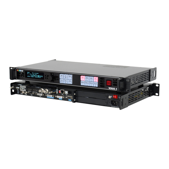
Page 8: Product Overview
VENUS X1 supports EDID editing for VGA, DVI, HDMI input ports and read EDID for output ports, support EDID modify by windows control program. PC modified EDID, users can edit the EDID of input port according to the resolution of outputs to achieve the optimal input resolution. -
Page 9: Back Panel
DVI-I – DVI LOOP Connect to the DVI input of the next VENUS X1 or the device with DVI input. DB15 – VGA Connect to the monitor or LED display which has VGA interface. (This connector does not support hotplug). -
Page 10: Power Connection
WIFI Connect to Ethernet work for remote control by WIFI. Power Connection Power Switch Illuminated power switch. IEC – Power Input Main power input AC 85-264V Max 65W. Option Slots Input Option Slots 1.2.3 Range of inputs are available for user fitting. Refer to Product Input Options. -
Page 11: Front Panel
Push the button to enter to the PIP menu items – refer to Setting. VENUS X1 V1.5 can not support DSK function button. SAVE Button Save all current settings with the VENUS X1 to 1 of the 36 available slots. For details, please refer to Saving Views. - Page 12 When connect USB signal, it reused the move next button, push the button to play the next USB video file. LOAD Button Restores/Loads all current settings with the VENUS X1 from 1 of the 36 available slots. For details, please refer to Recall Saved Settings.
-
Page 13: Dimension
1.2.3 Dimension Following is the dimension of VENUS X1 for your reference:... -
Page 14: Chapter 2 Installing Your Product
Chapter 2 Installing Your Product 2.1 Plugging in Signals Connect signals to the product (ensure all devices are powered off first). Tighten connector screws/locks where provided. For connector protection and for additional cable support this product is fitted with protection frames on either side of the device. - Page 15 亮彩系列 AVDSP SERIES VENUS X1 INIT NETWORK FINISHED!
-
Page 16: Chapter 3 Using Your Product
Chapter 3 Using Your Product 3.1 Using the MENU Button Push the [MENU] button to enter the menu display. Turn the rotary knob to navigate to the menu item required. The symbol shows the current item. Push the knob to select and enter into the menu item. As shown in the figure below:... -
Page 17: Understanding The Menu Structure
3.2 Understanding the MENU Structure The MENU structure is shown in the figure below:... -
Page 19: Using The Menu
3.3 Using the Menu Use the menu system for convenient and intuitive operation. VENUS X1 OLED display shows the menu items. The OLED display will show the default state when the menu is not in use, or the operation has timed out. Using the MENU button and rotary knob in the front panel, the OLED display will show the corresponding menus according to user selections. -
Page 20: Understanding The Main Menu
Full Indicates whether the screen size is full size or screen size. Indicates the current is single image, image settings are available in the PIP menu. Fade Indicates whether transitions are CUT or FADE. Configure from the Transition menu. Live Indicates whether output video Live or whether FREEZE is active. - Page 21 ->HDMI/EXT ADJUST >> HDMI AUDIO >> EDID MANAGEMENT >> VGA SIGNAL TYPE >> ->USB CONTROL >> EXT CVBS CONTROL >> INPUT DETAIL Display the input source and input format. V UP Image to up zoom. V DOWN Image to down zoom. V UP/DOWN Image to up and down zoom.
-
Page 22: Output Menu
Select video or photo, default video. PLAY FILE Select the file to play. PLAY ORDER Select REPEAT ALL, RANDOM, ORDER, SINGLE CYCLE, SINGLE TRACK or PLAY LIST. PLAY STATE Select play or pause. CVBS PORT EXT CVBS Select PORT A or PORT B. CONTROL INPUT FORMAT Display the input format of CVBS. -
Page 23: Picture Menu
If image quality distorts by improper operation, it can be recover by reset. DVI1 Select DVI1 OUTPUT or DVI LOOP, and select DVI mode, bit depth and data range, or set DE. If image quality distorts by improper operation, it can OUTPUT be recover by reset. -
Page 24: Save Setup Menu
>> DELAY CALL REAL-TIME SAVE SAVE TO Save all current settings with the VENUS X1 to 1 of the 36 available slots. Restores/Loads all current settings with the VENUS X1 from 1 of the 36 LOAD FROM available slots. DELAY CALL Delay output time setting. -
Page 25: Led Management Menu
->DEVICE STATUS >> USER DEFINES BUTTON >> OLED LUMINANCE FAN CONTROL >> Display the serial number of the device. VERSION Display the software and hardware version of the device. TECH SUPPORT Display sales, after-sale service, email, website and telephone. Display the date, time, current time, last time, total time and boot times. DATE&TIME User can also change the date and time. -
Page 26: Language Menu
COLORLIGHT T7. SENDING CARD NO. Select No.1 or No.2 sender card. OUTPUT FORMAT Select the output format according to actual need. QUICK CONNECTION Include sending card set and receiving card set. For details, please refer to Set LED Display Connection. BRIGHTNESS Brightness setting, the adjustment range is 1%~100%. -
Page 27: Single Image Switching
3.4 Single Image Switching Default DVI for the current input source, if need switch other signal, for example, VGA, push the VGA button. DVI button light will be blinking after pushing the VGA button, representing the singal is about to switched. -
Page 28: Pip Setting
3.5 PIP Setting Enable the PIP function VENUS X1 supports seamless switching for single image and double images. Push the [PIP/DSK] button, the LED light is on, and enter to the PIP menu items. OLED module show as follows: ->PIP... -
Page 29: Set Led Display Connection
3.6 Set LED Display Connection VENUS X1 can realize three connection as follows connecting the Port D or Port U of one sending card to LED screen, connecting the both Port D and Port U of one sending card to LED screen, connecting the Port D and Port U of two sending cards to LED screen (PORT A or PORT B is for Colorlight, and PORT D or PORT U is for Linsn). - Page 30 (7) After setting, turn the knob, select <QUICK CONNECTION>, push the knob to confirm for next setting, shown as follows: SENDING CARD TYPE LINSN SENDING CARD NO. No.1 OUTPUT FORMAT >> ->QUICK CONNECTION >> ->SENDING CARD SET >> RECEIVING CARD SET >>...
- Page 31 After setting, turn the knob and choose <CONNECT CARD TYPE> according to actual connection mode. VENUS X1 support 8 kinds of connection modes, they are respectively. HEIGHT Offset (A/B) X Offset (A/B) Y ->CONNECT CARD TYPE >> Send to receiver after choose the connection mode, observe the display screen and make sure if display image is correct.
- Page 32 CONNECTION> option, push the knob to confirm, turn the knob, select the sending card type, for example, select Linsn (VENUS X1 supports Linsn and Colorlight sender card, for Nova sender card, it only support brightness and Gamma adjustment). Shown as follows: ->QUICK CONNECTION...
- Page 33 ->SENDING CARD SET >> RECEIVING CARD SET >> e. Turn the knob, select <RECEIVING CARD SET>, push the knob to confirm. Turn the knob again, and select <CHOOSE CABLE>, push the knob to confirm. Turn the knob, select PORT D1 and push the knob to confirm. SENDING CARD SET >>...
- Page 34 3. Connect the Port D and Port U of Two Sending Cards to LED Screen (1) First, make sure the device is in normal operation. (2) Select the input source, for example, DVI. (3) Connect four cables to Port U1, Port D1, Port U2 and Port D2 respectively. (4) Connect Port D1 and Port U1 of No.1 Sending Card to LED screen, the settings are same as “Connect the Port D and Port U of One Sending Card to LED Screen”.
- Page 35 ->SENDING CARD SET >> RECEIVING CARD SET >> (9) Turn the knob, select <RECEIVING CARD SET>, push the knob to confirm. Turn the knob again, and select <CHOOSE CABLE>, push the knob to confirm. Turn the knob, select PORT U2 and push the knob to confirm.
- Page 36 ->X SAVE TO SENDER CARD RESET (12) Same as above, set X of Port D of No.2 sending card as 360. Then connect the Port D and Port U of Two Sending Cards to LED Screen is finished. Rendering is as follows:...
-
Page 38: Split Setting
VENUS X1. User can also do cascade via DVI LOOP port, and it needs to select “DVI LOOP” for <DVI1 OUTPUT> in menus. - Page 39 ->SPLIT H TOTAL 1920 V TOTAL 1080 H POS ->V POS H SIZE 1920 V SIZE 1080 ADVANCE >> ->RESET SPLIT: Split function, can select “ON” or “OFF”. H TOTAL: LED screen Horizontal total size. V TOTAL: LED screen Vertical total size. H POS: This device display image Horizontal size.
-
Page 40: Scale The Image
3.8 Scale the Image Push the [SCALE] button, and enter to the scale menus as follows. 1920 ->H SIZE 1080 V SIZE H/V SIZE H POS ->V POS RESET User can adjust the following items by the rotary knob or number buttons. H SIZE: Width setting. -
Page 41: Set The Output Resolution
3.9 Set the Output Resolution 3.9.1 Select the Output Resolution 1. Push the [MENU] button, and enter to the menu items, turn the rotary knob, and select <OUTPUT>: INPUT >> ->OUTPUT >> PICTURE >> >> 2. Push the knob to confirm, and enter to the menu items as follows: ->STANDARD >>... - Page 42 For example, input refresh rate 60: CUSTOMIZED: ->1536×1536@60 7. After input all the values, push knob to enable VENUS X1 to output this resolution. VENUS X1 will take 5~10 seconds to enable this output resolution.
-
Page 43: Screen Size Setting
3.10 Screen Size Setting VENUS X1 supports the screen parameters to meet the requirement where user want to switch between scale screen size and full display size (like monitor). This is only enable for a single display window. Following is an example of a screen size is1408 x 832. -
Page 44: Zoom The Image
3.11 Zoom the Image The image can be zoom in horizontal or vertical separately, to meet the special effects required. Push the [MENU] button to go into the menu items, turn the rotary knob and select <INPUT>, push the knob to confirm. Turn the rotary knob again, select <ZOOM>, and enter to the zoom menus as follows: ->V UP V DOWN... -
Page 45: Text Overlay Setting
3.12 Text Overlay Setting Before setting the text overlay, please make sure the input channel of the text. For example, set VGA input as the text channel. Then make sure the channel that the text will overlay, for example, overlay the text on DVI channel. The operations are as follows: 1. - Page 46 The standard position and size is: ensure the VGA image overlay on the DVI image, display normally and without black edges. If there are black edges around VGA image, select <ZOOM> option in <INPUT> to adjust. 6. Set the text overlay mode: select <PRESET> option in <TEXT OVERLAY>, push the knob to enter into the <PRESET>...
-
Page 47: User Define Black Key
3.13 User Define BLACK Key Default the [BLACK] button as black function. Push the button, its LED light is on, the output will be switched to black, push the button again, its LED light is off, and output the video image. For more details, please refer to: Using Black Out. - Page 48 ->TEST PATTERN AUTO SWITCH There are 66 kinds of test patterns. If select <AUTO SWITCH>, VENUS X1 will output all the test patterns one by one, and the interval between is 1 to10S. Push the button again, its LED light is off, and output the video image.
-
Page 49: Transition Setting
3.14 Transition Setting Push the [MENU] button for two times, and enter to the transition function menus, transition menu shown as follows: ->DEINTERLACE IMAGE ENHANCE MODE DISSOLVE FADE TIME 0.5s ->ALPHA DEINTERLACE: Force Deinterlace function, select “ON” or “OFF”. ON: Force deinterlace. OFF: No deinterlace. -
Page 50: Set The Audio
3.15 Set the Audio Push the [MENU] button, the OLED module show the menu items, turn the knob, and select <AUDIO>, push the knob to confirm. INPUT >> OUTPUT >> >> ->AUDIO PICTURE >> ->MUTE VOLUME AUDIO IN IMAGE A HDMI/EXT AUDO EXTERNAL ->INPUT AUDIO CONFIG... -
Page 51: Using Black Out
Black out descriptions: Black signal realizes one-key-touch to a black screen. VENUS X1 provides black effect processing for output with cut black effect. Operation is as below: Push the [BLACK/0] button, then output will cut to BLACK, shown as below:... -
Page 52: Saving Views
3.17 Saving Views VENUS X1 provides 36 positions for saving or recording parameters. To save current parameters and settings: 1. Push the [SAVE/1] button, the button light is on, and enable the SAVE function. SAVE TO ->SAVE 1 Button is on can be saved Button flashes will be overwrite 2. -
Page 53: Recall Saved Settings
3.18 Recall Saved Settings VENUS X1 provides 36 positions for saving or recording parameters. To recall saved settings: 1. Push the [LOAD/6] button, the button light is on, and enable the LOAD function: RECALL SAVE ->SAVE 1 Button on is ready for recall Button flashes means just recall 2. -
Page 54: Chapter 4 Controlling Your Processor Remotely
Remotely 4.1 Using the XPOSE App for Android & iOS 1. Connection Connect the VENUS X1 to any LAN port of the wireless router via a network cable. The LAN port are marked with the red box. Shown in the figure below (connect from the left to right). - Page 55 Subnet (Wireless or cable terminals (Android or router) Apple IOS) Connect the LAN port VENUS wireless router VENUS X1 (3) System Setting Push the [MENU] button, and enter to the menu items, turn the knob and select <SYSTEM>. >> ->SYSTEM LED MANAGEMENT >>...
- Page 56 SUBNET MASK >> ->GATEWAY >> ① One LAN environment Set the <IP ADDRESS>, be sure set the same IP address for VENUS X1 and router. System default the IP address is 192.168.0.100. IP ADDRESS ->192.168.000.100 ② Multiple routers Be sure the router that connect to VENUS X1 is connected to the other routers.
- Page 57 Chapter 4: Controlling Your Processor Remotely Open APP Search Device Connect the Device Operate the Device (3) APP functions ① Switch & Display...
- Page 58 Chapter 4: Controlling Your Processor Remotely Single Image PIP Mode ② Scale & Crop Scale and crop setting. Including Image A and Image B. Drag the scroll bar in activity area to adjust the width, height, X and Y. Scale Crop User can also click “Edit”...
- Page 59 Chapter 4: Controlling Your Processor Remotely Scale Crop ③ Image Settings Brightness, contrast and color temp setting. Drag the scroll bar in activity area to adjust the R, G, B. If click “SYN”, the R, G, B will be adjusted synchronously. “Reset” will factory reset all the parameters.
- Page 60 And in output adjust, user can set DVI mode, bit depth, data range, DE, etc. Output Config Output Adjust ⑥ Save Settings Load scene is load the saved scenes. Save scene is save the adjusted parameters. VENUS X1 supports 36 groups of “Load Scene” and “Save Scene”.
- Page 61 Chapter 4: Controlling Your Processor Remotely Load scene Save Scene ⑦ Advanced Advanced function includes EDID manage and hot backup. In EDID manage, select the destination port and source file. VENUX X1 supports DVI, HDMI and VGA EDID manage. Hot backup includes 5 groups of backup inputs.
- Page 62 Chapter 4: Controlling Your Processor Remotely Factory Reset...
-
Page 63: Chapter 5 Ordering Codes
Chapter 5 Ordering Codes 5.1 Product 110-0001-01-2 110-0001-02-2 X1 with EXT module fitted 110-0001-03-2 X1 with Wi-Fi 110-0001-04-2 X1 with EXT & Wi-Fi 5.2 Options 5.2.1 Input Options 190-0001-02-1 VGA Input 1× VGA 190-0001-03-1 Display Port Input (DP1.2) 1 × Display Port 190-0001-04-1 DVI Input 1 ×... -
Page 64: Sender Cards
Chapter 5 : Ordering Codes 5.3 Sender Cards RCRCPJ00090 Linsn TS801 RCRCPJ00091 Linsn TS802 RCRCPJ00110 Nova MSD300 RCRCPJ00112 Nova MSD600 RCRCFJ00133 Colorlight S2... -
Page 65: Chapter 6 Support
Input jitter for I system of HDMI Question Change the input as P system Some HDMI input of VENUS X1 will jitter for the I system of HDMI, please change the input as P system. Troubleshooting Connect the HDMI signal to the EXT_HDMI input If user can’t change the input format as P system, please connect the I system... -
Page 66: There Is Flash Point When Output To The Led Screen
The DVI output port is loose or oxidation due to plug and pull frequently or long time no use, which may cause the signal attenuation. There are two DVI output ports on VENUS X1, please change to the other DVI output port and test again. -
Page 67: Hdmi, Dvi Input Offset Or Cannot Be Full Size Shown
6.1.6 HDMI, DVI Input Offset or cannot be Full Size Shown Frequently Asked HDMI, DVI input offset or cannot be full size shown Question Manual Adjust the HDMI, DVI and EXT HDMI, EXT DVI Push the [MENU] button, then choose <INPUT>, turn the knob and select Troubleshooting <DVI/EXT ADJUST>, push the knob to confirm. -
Page 68: Contact Us
Chapter 6: Support 6.2 Contact Us... -
Page 69: Chapter 7 Appendix
Chapter 7 Appendix 7.1 Specification CVBS Input (Standard) Number of Inputs Connector Standard BNC Socket Supported Standards PAL/NTSC Signal Level 1Vpp±3db (0.7V Video+0.3v Sync ) 75 ohm Multiplex 480i,576i VGA Input (Standard) Number of Inputs Connector Standard DB15 Socket Supported Standard VGA-UXGA Signal Level R, G, B, Hsync, Vsync:0 to1Vpp±3dB... - Page 70 Supported Resolution SMPTE:625/25/50 PAL, 525/29.97/59.94 NTSC, 1080P50/59.94/60,1080i50/59.94/60,720p50/59.94/60 VESA:800×600@60 I 1024×768@60 I 1280×768@60 I 1280×1024@60 I 1600×1200@60 I 1920×1080@60 Signal Level TMDS pwl,single pixel input,165MHz bandwidth Format Standard DVI 1.0 DVI Output (Standard) Number of Outputs Connector Standard DVI-I Socket Signal Level TMDS pw, 165MHz bandwidth Supported Resolution SMPTE:720p@50/60 | 1080p@50/60...
- Page 71 SMPTE 296M (HD): 1280×720/50 (1:1) I 1280×720/50 (1:1) SMPTE 125M (SD): 1440×487/60 (2:1), 525-line 487 generic SMPTE ITU-R BT.656 (SD): 1440×576/50 (2:1), 625-line generic. Belden 1694A cable: 150m at 2.97Gb/s Balance 250m at 1.485Gb/s 480m at 270Mb/s DVI IN+DVI LOOP (DL optional module) Interface Appearance Board Size 104.5(L)×19.5(W)(mm)...
- Page 72 Supported Bandwidth 10.8Gb/s Format Standard DP1.0 HDMI IN+HDMI LOOP (HL optional module) Interface Appearance Board Size 52(L)×19.5(W)(mm) HDMI Input Number of Inputs Connector Standard HDMI-A socket Supported Resolution SMPTE:625/25/50 PAL, 525/29.97/59.94 NTSC, 1080P50/59.94/60 I 1080i50/59.94/60, 720p50/59.94/60 VESA:800×600@60 I 1024×768@60 I 1280×768@60 I 1280×1024@60 I 1600×1200@60 I 1920×1080@60 Signal Level TMDS pwl, single pixel input,165MHz bandwidth...
- Page 73 Interface Appearance Board Size 52(L)×19.5(W)(mm) Number of Inputs Connector Standard BNC Socket Supported Standards PAL/NTSC Signal Level 1Vpp±3db (0.7V Video+0.3v Sync ) 75 ohm Multiplex 480i,576i VGA Input (VGA optional module) Interface Appearance Board Size 52(L)×19.5(W)(mm) Number of Inputs Connector Standard DB15 Socket Supported Standard VGA-UXGA...
- Page 74 Connector Card faucet , Standard 1/4 Socket Audio standard 48Kbps 24bit WIFI Hotspot Module Certification FCC/CE Wireless Standard 802.11 b/g/n Frequency range 2.412GHz-2.484GHz 802.11b: +20dBm (Max.) 802.11g: +18dBm (Max.) Transmit Power 802.11n: +15dBm (Max.) Configurable 802.11b: -89dBm 802.11g: -81dBm Receiver Sensitivity 802.11n: -71dBm Antenna Option External: I-PEX Connector...
-
Page 75: Software Upgrade
7.2 Software Upgrade The upgrade steps are as follows: 1. Connect the USB interface of VENUS X1 to the computer with a USB cable. 2. Plug in the power cord, and make sure the device is in normal operation. 3. Open XTOOL. Icon like Click “语言/Language”... - Page 76 OK, red means the connection failed). The Bottom corner can read the device type and SN number. 5. Select upgrade file and start to upgrade. Click "Bin File" to select the .bin file in the "Upgrade Files" folder of VENUS X1 firmware package. Click“all”,XTOOL will compare the version number and the subroutine version number of the package automatically.
- Page 77 Chapter 7: Appendix 6. Click "upgrade", and it will pop-up "whether to upgrade firmware" dialog box, click "OK" to upgrade: 1.1.1. Check the upgrade progress by scroll bar, you can press the "stop" to stop the upgrade.
- Page 78 Chapter 7: Appendix 7. After the upgrade is completed, the “New Version Upgrade Complete ” dialog box will pop out. At the same time, the device will emit a "buzz" sound. When it stop, the device will be restarted. 1.1.2. Press”OK”,restart the device. Attention If the serial port can't be recognized, check whether the USB serial port driver installed or not.
- Page 79 Chapter 7: Appendix software. 32bits:CP_V1.3.1_Setup_x32 64bits:CP_V1.3.1_Setup_x64 2. The package contains optional module and wireless module, if there is no optional module, or a wireless WIFI version, the item will show "skipped".
-
Page 80: Installing Options
7.3 Installing Options 7.3.1 Installing Input Module VENUS X1 is based on replaceable input optional modules structure, user can install or replace the optional module according to actual need, the specific installation steps are as follows: Install the Optional Module 1. - Page 81 Chapter 7: Appendix 3. Push the input modules into the device along the slide rail, and screw the captive screws, then install the input blocks, as shown in figure: 4. If install the SDI input module, please screw the SDI interface, as shown in figure: 5.
- Page 82 Chapter 7: Appendix Captive Screw 2. Unscrew the fixed screws of input module, as shown in figure: Fixed screw of input module 3. Take out the input modules that will replace, as shown in figure:...
- Page 83 Chapter 7: Appendix 4. Install the input module that user need, as shown in figure: 5. Fix the input modules on the plate with screws, as shown in figure:...
- Page 84 Chapter 7: Appendix Fixed screw of input module 6. Push the input modules into the device along the slide rail, and screw the captive screws, as shown in figure: Captive Screw 7. Lock the input block, as shown in figure:...
-
Page 85: Installing Wifi Module
Chapter 7: Appendix 7.3.2 Installing WIFI Module 1. Remove the 5 screws on the top cover, and move the top cover, as shown in the figure below: 2. Install the WIFI module as shown in the figure below: lock the WIFI module with 2 pieces of 2*5 flat head screws, then connect the antenna junctor and the connector with the WIFI antenna cable. - Page 86 Chapter 7: Appendix 4. Lock the top cover with 5 screws, and installing WIFI module is finished.
-
Page 87: Connect Wifi
Chapter 7: Appendix 7.4 Connect WIFI 1. Plug VENUS X1 into the power cord, and turn the power switch on the rear of the product to the ON position. 2. Right click the wireless icon on the lower right corner, and select “Wireless Network Connection”, then select “VENUS-X1-0048", and click “Connect”. - Page 88 Chapter 7: Appendix 6. The log area will synchronization data, as shown in the figure below: 7. If it shown “WiFi OK”, click the “Open Comm” icon, as shown in the figure below, and Wifi is connected.
-
Page 89: Shortcuts
Chapter 7: Appendix 7.5 Shortcuts Lots of shortcuts are provided in VENUS X1, shown as follows: Function Shortcuts MENU+TAKE Button Change the language Push the MENU and TAKE button for 3 seconds will change the language. MENU Button Change to Transition Push the button two times will enter to the transition menus. -
Page 90: Terms & Definitions
Chapter 7: Appendix 7.6 Terms & Definitions The following terms and definitions are used throughout this guide. “ASCII”: American Standard for Information Interchange. The standard code consisting of 7-bit coded characters (8 bits including parity check) used to exchange information between data processing systems, data communication systems, and associated equipment. - Page 91 Chapter 7: Appendix redder the light. Benchmark color temperature for the A/V industry include 5000°K, 6500°K, and 9000°K. “Contrast ratio”: The radio of the high light output level divided by the low light output level. In theory, the contrast radio of the television system should be at least 100:1, if not 300:1. In reality, there are several limitations.
- Page 92 Chapter 7: Appendix International Standards Organization working on algorithm standards that allow digital compression, storage and transmission of moving image information such as motion video, CD-quality audio, and control data at CD-ROM bandwidth. The MPEG algorithm provides inter-frame compression of video images and can have an effective compression rate of 100:1 to 200:1.
- Page 93 Chapter 7: Appendix signal for input to an image processor, transmission path or to improve its quality when presented on a particular display. “SDI”: Serial Digital Interface. The standard based on a 270 Mbps transfer rate. This is a 10-bit, scrambled, polarity independent interface with common scrambling for both component ITU-R 601 and composite digital video and four channels of (embedded) digital audio.
-
Page 94: Revision History
2. Update the menu tree. 3. Update the product picture. 4. Update the dimensions drawing 5. Update the specification. 6. Update “Optional Module Installation and Replacement Instruction”. 7. Add “VENUS X1 Connect APP Control Operation”. V1.3 2016-05-05 0003# 1. Update the product picture. Vira 2.
Need help?
Do you have a question about the VENUS X1 and is the answer not in the manual?
Questions and answers