RGBlink X3 User Manual
Hide thumbs
Also See for X3:
- User manual (96 pages) ,
- Quick start manual (39 pages) ,
- User manual (76 pages)
Table of Contents
Advertisement
Quick Links
Download this manual
See also:
User Manual
Advertisement
Table of Contents

Related Manuals for RGBlink X3


Summary of Contents for RGBlink X3
- Page 1 USER MANUAL Article No: RGB-RD-UM- X3 E001 Revision No: V1.5...
-
Page 2: Table Of Contents
Chapter 2 Installing Your Product......................10 2.1 Plugging in Signals........................10 2.2 Plugging in Main Power.......................10 2.3 Turning on Your Product......................10 2.4 Connect X3 and Computer......................11 Chapter 3 Using Your Product........................12 3.1 XPOSE Installation........................12 3.2 XPOSE Controls X3........................16 3.2.1 Login in XPOSE........................ -
Page 3: Declarations
30 days after the transfer of risks. In the event of justified notice of compliant, RGBlink can repair the fault or provide a replacement at its own discretion within an appropriate period. If this measure proves to be impossible or unsuccessful, the purchaser can demand a reduction in the purchase price or cancellation of the contract. -
Page 4: Operators Safety Summary
Normal wear as well as normal maintenance are not subject to the guarantee provided by RGBlink either. The environmental conditions as well as the servicing and maintenance regulations specified in this manual must be complied with by the customer. - Page 5 If there is damage, notify the shipping carrier immediately for all claims adjustments. Site Preparation The environment in which you install your X3 should be clean, properly lit, free from static, and have adequate power, ventilation, and space for all components.
-
Page 6: Chapter 1 Your Product
Chapter 1 Your Product 1.1 In the Box AC Power Cord USB Cable Network Cable HDMI to DVI SDI Cable DVI Cable Cable Screw Driver Antistatic Bag Note: AC Power Cable supplied as standard according to destination market. User Manual... -
Page 7: Product Overview
DVI, VGA, HDMI, CVBS, SDI and USB (for media files play) or video sources. Hundreds of additional video or graphic sources can be input to the X3 using the RGBlink AVDXP Matrix and Router. Multiple X3 can be cascaded to create very large display arrays. -
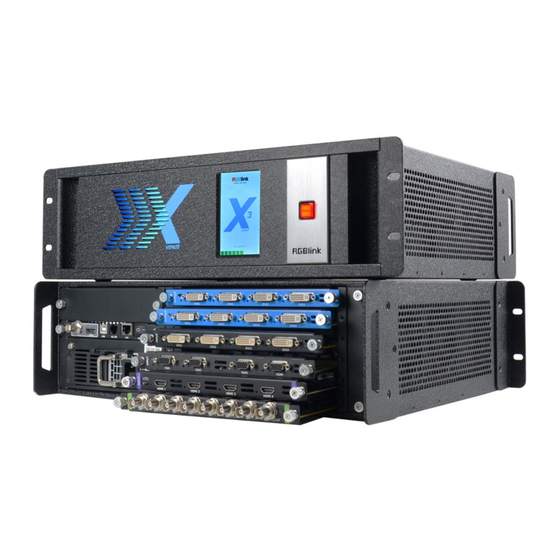
Page 8: Front Panel
1.2.1 Front Panel OLED Panel Show the input shot and output slot information, device status, COM. Version, IP address and serial address. POWER Power button, long push the button, the device can be boot up. Under normal running state, push the button once, the info shown on OLED can be refreshed once ;... -
Page 9: Rear Panel
1.2.2 Rear Panel Chassis Module Structure 2 output module slots Genlock interface 4 input module slots Power Switch and Power Module Communication ports Input Interface 4 input slots,supports input modules including DVI, VGA, HDMI, USB, CVBS, 4K@60HZ module and 12G-SDI. For details, please refer to Specification at the end of this document. -
Page 10: Dimension
Power Connection Power Switch Connect the windows control program and device upgrade. Power Interface AC:100-240V Power: Max 65W Power Supply Interface:IEC-3 1.2.3 Dimension Following is the dimension of x3 for your reference: User Manual... -
Page 11: Chapter 2 Installing Your Product
Chapter 2 Installing Your Product 2.1 Plugging in Signals Connect signals to the product (ensure all the device are all power off first).Tighten connector screws/locks where provided. 2.2 Plugging in Main Power Connect IEC cable to device and plug into wall socket. Turn on power at wall socket. 2.3 Turning on Your Product Turn on the power switch on the real panel. -
Page 12: Connect X3 And Computer
COM. Versions. IP address and serial number. 2.4 Connect X3 and Computer Use network cable to connect the X3 and computer as the following picture show: Set the IP address of the computer and make sure the computer and the device are in same network range. -
Page 13: Chapter 3 Using Your Product
Chapter 3 Using Your Product 3.1 XPOSE Installation Environment Requirements: Processor: 1 GHz or above 32 bit or 64 bit processor Memory: 2 GB or more Graphics: Support DirectX 9 128M or above (open AERO effect) Hard disk space: Above 16G (primary partitions, NTFS format) Monitor: Resolution must be 1280 x720 pixel or above (it can not display normally if the resolution is lower than 1280 x720) Operating system: Windows 7 or above (full version, not Ghost version or compact version) - Page 14 Select “Browse...” to select the XPOSE software install location: Note: User should get the rights in “Roles Management” when install the software to disk C if the system is Windows 7 or above. Click “Install”: User Manual...
- Page 15 During installation, it will pop up the window of InstallShield Wizard for Virtual Com port: If user install the XPOSE software for the first time, click “Next User Manual...
- Page 16 Then click “Install", as shown in the figure below: Click “Finish” and complete the installation, as shown in the figure below: Click “Finish” and is ready to run the XPOSE : User Manual...
-
Page 17: Xpose Controls X3
Double click the icon on the desktop. Log in interface will be enter after opening, the user name is Admin, and there is no password, select “VEUNS X3”, and enter the XPOSE by clicking “Login”. If user want to change the language to Chinese, click the drop down arrow after “Language” and select “Chinese”, as shown in the figure below, then click “Login”... - Page 18 X POSE management software interface is shown as follows. XPOSE management software contains the functions including: Web Links, Search, Output Settings, Operation Mode, Input Settings, Access Control,System Settings,Slave Unit and Logout. In the following parts, we will introduce these in detail. User Manual...
-
Page 19: Connect With The X3
3.2.2 Connect with the X3 Click the shortcut “Search” on the operation interface. Then it will search the X3, and show the device name, device number and IP after search, as shown in the figure below: Finally, click the VEUNS X3 to connect, as shown in the figure below:... - Page 20 Note: Right click the device, user can set tag name. The tag will be added behind X3 . It can help users to differentiate the devices when more than one X3 are searched. If select “Clean Tag Name”, the modified tag name will be cleared.
-
Page 21: Output Settings
3.2.3 Output Settings Click the “Output Settings”, and enter the interface as follows: Output Setting, DE Setting, Test pattern and OSD are included in output settings, specific as: User Manual... - Page 22 Output Setting Click the “Output Setting”, and pop-up window as follows: Output: Click the drop down arrow after the format, and select the output resolution in the pull-down menus according to actual need. Custom: The width, height and frequency can be set if select “Custom” in “Format”. Click “Setting”...
- Page 23 DE Setting Click the “DE Setting”, and pop-up window as follows: Output Port: Select one port or all ports. Output Type: Select DVI or HDMI. Color Range: Select image or video. Bits: 8 bits can be selected if the output type is DVI. 8 bits, 10 bits and 12 bits can be selected if the output type is HDMI.
- Page 24 Output: User can select any board among the four boards. Color Choice: Signal source, color bar and pure color can be selected. #FFFFFF: Preview the corresponding RGB values and the color. Click the “OSD”, and pop-up window as follows: Output Mode: One output mode or more output mode can be selected. In one output mode, user need to enable the OSD function and select the output first.
-
Page 25: Operation Mode
3.2.4 Operation Mode Click the “Operation Mode”, and enter to the interface as follows: Fade Mode, Videowall Mode, Matrix Mode, Preview Mode, Link Mode and 3D-Mode are included in operation mode, specific as follows: Videowall Mode Click the “Videowall Mode”, and enter to the interface as follows: User Manual... - Page 26 Signal List The signal list is shown as follows: It displays the input module type, the quantity of inputs and input format. Right click the input for the following settings: LOGO: Right click HDMI/DVI input, and select “LOGO”, it will enter to the LOGO menu items. User Manual...
- Page 27 LOGO capture: Select the LOGO, there are 10 groups of LOGO. The image is frozen when capture LOGO. Hide LOGO: Select “Hide LOGO”, the LOGO will be hidden. Display LOGO: Select the number of “Display LOGO”. Live/Freeze: Select “Live/Freeze”, the image is frozen. Cancel it, the image is live. Change Name: Select “New Name”, and input the new name, click “OK”...
- Page 28 Mirror: Enable or disable the mirror function, default “OFF”. Bypass Mode: Enable or disable the bypass mode. When select “ON”, the output format will be the same with the input format. Alpha: Set the alpha, the adjustment range is 0~128. Sharpness: Set the sharpness, the adjustment range is 0~100.
- Page 29 Output Setting Click “Monitor” shortcut , it will enter the interface as follows: In videowall mode, there are max 16 image in the output interface, group of two outputs, one output module can display 8 images. Split Mode: Default quick split “OFF”. User can enable the quick split function by sliding the switch to “ON”.
- Page 30 Unequal Split Type: User can custom the H total, V total, row and column, for example, set H total as 6720, V total as 3960, Row and Column as 4, as shown in the figure below: Click “OK”, it will pop up windows as below: User Manual...
- Page 31 Set H1, H2, H3, V1, V2 and V3. For example, set H1 as 960, H2 as 1920, H3 as 960, V1 as 800, V2 as 1080, and V3 as 1000, the layout is shown in the figure below: LCD Type: Slide the monitor type switch, and select “LCD Type”. Besides H total, V total, row and column, user can custom the top border, bottom border, left border and right border in LCD type, as shown in the figure below: User Manual...
- Page 32 Note Top border and bottom border, left border and right border are changed equivalently. For example, if set top border as 100, bottom border will be changed to 100 automatically, and if set left border as 200, right border will be changed to 200 automatically.
- Page 33 Monitor Size changed equivalently: Select any monitor, for example, select monitor 1, and adjust the size. Click this monitor, then press button C and don’t let go, select the monitor that will set, the size of the selected monitor will be changed to the same size of monitor 1, as shown in the figure below: Rotation: Select the monitor, and set the rotation as 0°, 90°, 180°...
- Page 34 mouse, then the layer will be moved, release the mouse when moved to the suitable location. But this method can only adjust the size and location roughly, if an accurate adjustment is needed, the second method can be used. b. Select the layer to be adjusted, and set the X, Y, width and height in the bottom of the interface. Hierarchical relations between layers: After creating the layers, the hierarchical relations can be changed by the following: click the shortcut key bring layer to top “...
- Page 35 Scale: Set the X, Y, width and height. Crop: Crop the left, top, width and height. Display Mode: Select “Live” or “Freeze”. Mirror: Enable or disable the mirror function, default “OFF”. Alpha: Set the alpha, the adjustment range is 0~128. Sharpness: Set the sharpness, the adjustment range is 0~100.
- Page 36 EDID Click the EDID shortcut “ ”, and pop-up window as follows: The special display project or LED display application would like to require special resolution settings to meet the requirement. Select the input or output board to read and write the EDID. As shown in the figure below: If select the 4K input card, as shown in the figure below: Click the input port, and set the width, height and frequency.
- Page 37 Loop Click the loop shortcut “ ”, and pop-up window as follows: Slide the loop switch to enable or disable the loop function for the bank. If select “ON”, the bank play time can be set. Sync Click the sync shortcut “ ”...
- Page 38 Save Script Click the save script shortcut “ ”, user can save the data to the computer. Factory Reset Click the factory reset shortcut “ ” to reset to factory settings. Out Card Set Click the out card set shortcut “ ”, and pop-up window as follows: Click any output, and pop-up window as follows: X, Y, width, height, rotate can be set.
- Page 39 If user need to connect to the LED display, or there is deviation in splitting, enter to the advanced setting, and scale or crop the image. Page Set Click the shortcut “ ”, and pop-up window as follows: Save Page: Click any one of page 1~page 16. The button light will be on and then turn to gray if save the scene successfully.
- Page 40 Short Key Click the shortcut “ ”, and pop-up window as follows: Use shortcut key to operate fast and easily. Take Default display the Take window. Click the shortcut “ ”, it will hide the Take window, and click the shortcut again, it will pop-up the window. The Take window is shown as the figure below: Set the alpha time, and the adjustment range is 0~10S.
- Page 41 Click “OK”, and the system will synchronize the data, about 5 seconds later, it will enter the interface as follows: The operations for Fade mode are same with Videowall mode. The difference is, in Fade mode, there is only one layer in one output, user can adjust the size and position of the layer. Matrix Mode Click the “Matrix Mode”, and pop-up window as follows: Click “OK”, and the system will synchronize the data, about 5 seconds later, it will enter the...
- Page 42 In matrix mode, any operations are unavailable except signal selection, bank selection, alpha time and black scene setting. Default source 1 to monitor 1, source 2 to monitor 2, and so on. Select the signal, and drag it to the source that will set. For example, set signal 9 for source 1, as shown in the figure below: Note: Click the monitor (the border of the monitor will turn to red), then double click the signal (the border of the monitor will turn to yellow), the signal will be switched to the monitor.
- Page 43 Preview Mode Click the “Preview Mode”, and pop-up window as follows: Click “OK”, the system will synchronize the data, and it will finish about 5 seconds later, click “OK”, it will enter the interface as follows: In preview mode, Default outputs 2.4.6.8 as preview channel and outputs1.3.5.7 as program channel.
- Page 44 Transition Time: Users can slide the bar to set the transition Time, rang from 0-10s Preview Logo Setting: Hide or Display the “Preview” logo on the preview monitor. Black Out: On or Off Auto Take: doesn’t work under Preview Mode CUT:switch PST to PGM display instantaneously Take:swtch PST to PGM in transition time.
- Page 45 3D-Mode Click the “3D-Mode”, and pop-up window as follows: Click “OK”, the system will synchronize the data, and it will finish about 5 seconds later, click “OK”, it will enter the interface as follows: Default 2D-Mode, right click the signal, and select “Set Input 3D Type”, it will enter the interface as follows: User can select “3D-Mode One InputSource”...
-
Page 46: Input Settings
The other operations are same with “Videowall Mode”. 3.2.5 Input Settings Click the “Input Settings”, and enter the interface as follows: DSK settings, source backup, source merge , 4K input set and H264 Input Settings are included in input settings, specific as follows: DSK Settings Click the “DSK Settings”, and pop-up window as follows: Select DSK ON, as shown in figure... - Page 47 Source Backup Click the “Source Backup”, and pop-up window as follows: Enable the hot backup function, as shown in figure , and set the backup signal for Hot Backup 1 to Hot Backup 8. It will switch to the backup signal if the signal is interrupted. Source Merge Click the “Source Merge”, and pop-up window as follows: The DVI and S-HDMI input optional module support signal merger.
- Page 48 figure below: User can also scale or crop the layer. 4K Input Set Click the “4K Input Set”, and pop-up window as follows: Input Module: Click the pull down arrow to select the 4K input module. Source: 1. If select 4Kx2K, user can only select one source from source 1 (select one among DVI, HDMI and DP).
- Page 49 2. Open the videowall mode, it will display the combined HDMI signals in the signal list, shown as follows: 3. Drag any signal to the monitor, the two outputs will combine to a picture with 3840x1080 automatically, shown as follows: User Manual...
- Page 50 H264 Input Settings Click the “H264 Input Settings”, and pop-up window as follows: Input Card:The default input card is input card 1. Input Pot:Users can select input port 1&2 or input port 3&4 IP Set:If select “ IP Set“, users can set IP address,Netmask,Gateway,DNS and MAC. Network URL Set :...
-
Page 51: Access Control
3.2.6 Access Control Click the “Access Control”, and enter the interface as follows: Role management and rights management are included in access control, specific as follows: Role Management Click the “Role Management”, and pop-up window as follows: Add: Input the user name and password, and select the user type as “Admin’ or “Users”, click “Add”... - Page 52 Rights Management Click the “Rights Management”, and pop-up window as follows: Select the admin or users in user’s list, then click the rights in “Managements Detail”. Click “OK” after setting. User can operate the rights that selected. User Info: Display all the Admin or Users list, double click it will unfold or fold the list. Management Details: The admin can manage all the admin users and users user.
-
Page 53: System Settings
3.2.7 System Settings Click the “System Settings”, and enter the interface as follows: Connect Setting, System information, IP settings, factory reset, power on settings and help document are included in system settings, specific as follows: Connect Setting Click the “Connect Setting”, and pop-up window as follows: Select the serial connect and net connect, the software will search all the devices if not select “Search by this configuration”. - Page 54 If select “Net Connect” and “Search by this configuration”, the software will search all the devices with corresponding IP. System Information Click the “System Information”, and pop-up window as follows: Display the software version information. Including device model, serial number, IP address, firmware version, etc.
- Page 55 Select “Remove the LOGO”, and click “OK”, the LOGO will be removed. Select “Remove EDID”, and click “OK”, the EDID will be removed. Power On Setting Fan Control Click the “Power On Setting Fan Control”, and pop-up window as follows: Delay Power-On Setting Power Switch : On or Off.
-
Page 56: Slave Unit
Click the “Slave Unit”, and enter the interface as follows: If need more X3 devices to be backup, connect all X3 devices into one router, Users can type in the Device Numbers and Set Numbers, then it will pop up the following window:... -
Page 57: Logout
3.2.9 Logout Click the “Logout”, and enter the interface as follows: Click “OK” will logout the XPOSE. User Manual... -
Page 58: Chapter 4 Ordering Codes
Chapter 4 Ordering Codes Product 310-0003-11-0 4.2 Options 4.2.1 Input Options 190-0003-01-0 Quad DVI Input Module 190-0003-02-0 Quad D- HDMI Input Module 190-0003-03-0 Quad VGA Input Module 190-0003-04-0 Quad D-SDI Input Module 190-0003-06-0 CVBS Input Module 190-0003-07-0 Quad USB Input Module 190-0003-11-0 4K@30Hz Input Module 190-0003-25-0... -
Page 59: Chapter 5 Support
Chapter 5 Support 5.1 Contact Us User Manual... -
Page 60: Chapter 6 Appendix
Chapter 6 Appendix 6.1 Specification CVBS Input Module Interface Appearance Board Size 216*200*20(mm) Number of 8 (4 Inputs and 4 backup) Connectors Connector Standard BNC Socket Supported Standards PAL I NTSC I SECAM Signal Level 1Vpp±3db (0.7V Video+0.3v Sync ) 75 ohm Supported 480i I 576i Resolution... - Page 61 1920x1200@60 | 2048x1152@60 | 2560x816@60 Signal Level TMDS pwl, single pixel input,165MHz bandwidth Format Standard Single Link DVI USB Input Module Interface Appearance Board Size 216(L)×20(W)(mm) Number of Connectors Connector Standard USB port Supported Standard Support general Image and video formats HDMI Input Module Interface Appearance Board Size...
- Page 62 Number of 8 (4 Input, 4 Loop) Connectors Connector Supported SMPTE 480i | 576i | 720p@50/60 | 1080i@59.94/60 | Resolution 1080p@23.98/24/25/29.97/30/59/59.94/60 | 1080psf@23.98/24/25/29.97/30 Supported Standard SMPTE 425M (Level A & B) | SMPTE 424M | SMPTE 292M | SMPTE 259M-C | DVB-ASI 12G-SDI Input Module Interface Appearance...
- Page 63 Connector RJ45 Supported 176x144@60 | 240x180@60 | 320x180@60 | 320x240@60 | 320x256@60 | Resolution 352x228@60 | 352x480@60 | 400x224@60 | 400x320@60 | 480x270@60 | 480x272@60 | 480x320@60 | 480x360@60 | 480x384@60 | 480x480@60 | 544x480@60 | 608x448@60 | 640x360@60 | 640x480@60 | 704x576@60 | 720x404@60 | 720x480@60 | 720x540@60 | 720x576@60 | 850x480@60 |1024x576@60 | 1280x720@60 | 1680x1056@60 | 1920x1080@60...
- Page 64 |2048x1152@60 SDI Output Module Interface Appearance Board Size 216(L)×20(W)(mm) Number of Connectors Connector BNC interface Signal level 800mV±10% Supported Standard SMPTE 425M - 3G Level A Format Supported SMPTE 480i | 576i | 720p/50/59.94/60 | 1080i/50/59.94/60 Resolution |1080p/50/59.94/60 Equalization Belden 1694A 100m HD 1.485G, 300m SD 270Mbps 2K HDMI Output Module Interface Appearance Board Size...
- Page 65 Interface Appearance Number of HDMI-A Connectors Supported SMPTE 720p@60|1080p@60|2160p@60 Resolutions VESA 1280x720@60 | 1360x768@60 | 1366x768@60 |1600x900@60 | 1920x1080@60 | 2540x1440@60 | 3480x2048@60 |3840x2160@60 Supported Standard HDMI 2.0 Communication Interface Appearance Board Size 165(L)×19(W)(mm) Genlock Number of Connectors Connector BNC (Genlock Y/H/V) HDMI (Genlock Loop) Control Number Connectors...
-
Page 66: X3 User Manual
6.2 Installing Options X3 supports replaceable input and output optional modules, user can install or replace the optional module according to actual need. Take X3 for example, the specific installation steps are as follows: Install the Optional Module 1. Unscrew the 2 captive screws in input modules block, and pull out the input module... - Page 67 2. Install the input module: For the whole PCB input module with DVI or HDMI interface, fix the input module on the plate with 2 M3*4 flat screws, also need to install the 2G Micro SD card. Micro SD card DVI input module: For the joined PCB input module with CVBS, HDMI, VGA, USB or SDI interface, fix the input module on the plate with 2 M3*4 flat screws and 2 M3*4 round head screws.
- Page 68 HDMI input module: VGA input module: CVBS input module: User Manual...
- Page 69 USB input module: 3. Fix the input module block with fixed screws, as shown in figure: 4. Push the input modules into the device along the slide rail, and screw the captive screws, as shown in figure: User Manual...
- Page 70 Note: The install steps of output module installation and input/output module replacement are the same as above. User Manual...
- Page 71 6.3 Terms & Definitions The following terms and definitions are used throughout this guide. “ASCII”: American Standard for Information Interchange. The standard code consisting of 7-bit coded characters (8 bits including parity check) used to exchange information between data processing systems, data communication systems, and associated equipment.
- Page 72 “Color temperature”: The color quality, expressed in degrees Kelvin(K), of a light source. The higher the color temperature, the bluer the light. The lower the temperature, the redder the light. Benchmark color temperature for the A/V industry include 5000°K, 6500°K, and 9000°K. ...
- Page 73 degree of compression can be adjusted, allowing a selectable tradeoff between storage size and image quality. JPEG typically achieves 10:1 compression with little perceptible loss in image quality. Produces blocking artifacts. “MPEG”: Motion Picture Expect Group. A standard committee under the auspices of the International Standards Organization working on algorithm standards that allow digital compression, storage and transmission of moving image information such as motion video, CD-quality audio, and control data at CD-ROM bandwidth.
- Page 74 a given color in any image is free from white. The less white in a color, the truer the color or the greater its saturation. On a display device, the color control adjusts the saturation. Not to be confused with the brightness, saturation is the amount of pigment in a color, and not the intensity.
- Page 75 “VGA”: Video Graphics Array. Introduced by IBM in 1987, VGA is an analog signal with TTL level separate horizontal and vertical sync. The video outputs to a 15-pin HD connector and has a horizontal scan frequency of 31.5 kHz and vertical frequency of 70 Hz (Mode 1, 2) and 60 Hz (Mode 3).
- Page 76 6.4 Revision History The table below lists the changes to the Video Processor User Manual. Format Time ECO# Description Principal V1.0 2015-01-06 0000# Release. Vira V1.1 2015-05-07 0001# 1. Add the optional module. Vira 2. Update the menu tree. 3. Update the windows control program.
Need help?
Do you have a question about the X3 and is the answer not in the manual?
Questions and answers