Table of Contents
Advertisement
Quick Links
Advertisement
Table of Contents

Related Manuals for RGBlink X14


Summary of Contents for RGBlink X14
- Page 1 USER MANUAL USER MANUAL Article No: RGB-RD-UM-X14 E001 Revision No: V1.1...
-
Page 2: Table Of Contents
1.2.3 Dimension..........................9 Chapter 2 Installing Your Product........................10 Chapter 3 Use Your Product........................... 12 3.1 Install XPOSE 2.0 Software.......................12 3.2 Control X14 By XPOSE 2.0........................16 3.2.1 Log in XPOSE 2.0........................16 3.2.2 Topology Diagram......................... 18 3.2.3 System Setting........................22 3.2.4 Output | Input | Overview.................... -
Page 3: Declarations
RGBlink. If the purchaser or a third party carries out modifications or repairs on goods delivered by RGBlink, or if the goods are handled incorrectly, in particular if the systems are commissioned operated incorrectly or if, after the transfer of risks, the goods are subject to influences not agreed upon in the contract, all guarantee claims of the purchaser will be rendered invalid. -
Page 4: Operators Safety Summary
The environmental conditions as well as the servicing and maintenance regulations specified in this manual must be complied with by the customer. Operators Safety Summary The general safety information in this summary is for operating personnel. Do Not Remove Covers or Panels There are no user-serviceable parts within the unit. - Page 5 The AC Socket-outlet should be installed near the equipment and be easily accessible. Unpacking and Inspection Before opening X14 processor shipping box, inspect it for damage. If you find any damage, notify the shipping carrier immediately for all claims adjustments. As you open the box, compare its contents against the packing slip.
-
Page 6: Chapter 1 Your Product
Chapter 1 Your Product 1.1 In the Box AC Power Cord DVI Cable Network Cable HDMI to DVI Cable HDMI Cable USB Cable Note: AC Power Cable supplied as standard according to destination market. USB is contained on the Warranty/Registration Card. Please keep. User Manual... -
Page 7: Product Overview
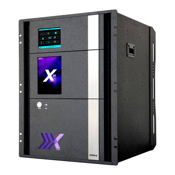
For entire video display systems, X14 brings a new level of efficiency, capability and control. Supporting up to massive 52 inputs and up to 40 outputs, X14 truly brings together large videos systems for system-in-box approaches to video presentation and integration. Modular throughout RGBlink technologies support user fit input and output signals with each slot configurable up to 4K/UHD resolutions at full frame rates. -
Page 8: Back Panel
1.2.1 Back Panel Communication board 13 slots for input modules 10 slots for output modules 2 slots for modular power supplies User Manual... -
Page 9: Front Panel
1.2.2 Front Panel 5.6 Inch TFT-LCD Display OSD Displays the input slot and output slot information, device status, COM. Version, IP address and serial number. 8 Inch TFT-LCD Display Monitor screen, to preview the pictures of the selected input USB 2.0 Prepared for keyboard or mouse to connect Power Power button, to turn on the device... -
Page 10: Dimension
1.2.3 Dimension Following is the dimension of X14 for your reference: User Manual... -
Page 11: Chapter 2 Installing Your Product
Make sure all devices are powered off first 2. Connect to computer Use CAT5 or CAT6 to connect Ethernet 1 port on the communication board of X14 and computer, Or RS232 serial cable connect UART port on the communication board of X14 and computer. - Page 12 And displays the input slot and output slot information, device status, COM. version, IP address and serial number after completing initialization Note:If you need reboot the device, make sure the power light above the power module totally goes out before pressing the power button, otherwise, blur screen may easily happen. User Manual...
-
Page 13: Chapter 3 Use Your Product
Chapter 3 Use Your Product 3.1 Install XPOSE 2.0 Software Environment Requirements: XPOSE: version 2.0.0.0 or above Window Processor: 1 GHz or above 32 bit or 64 bit processor Memory: 4 GB or more Graphics: Support DirectX 9 128M or above (open AERO effect) Hard disk space: Above 16G (primary partitions, NTFS format) Monitor: Resolution must be 1920x1080 pixel or above (it can not display normally if the resolution is lower than 1920x1080) - Page 14 Click Click “Browse...” to select the XPOSE software install location: Click “Install”: During installation, it will pop up the window of Install Shield Wizard for Virtual Com port: User Manual...
- Page 15 If user install the XPOSE software for the first time, click “Next Then click “Install", as shown in the figure below: User Manual...
- Page 16 Click “Finish” and complete the installation, as shown in the figure below: Click “Finish” and is ready to run the XPOSE : User Manual...
-
Page 17: Control X14 By Xpose 2.0
3.2 Control X14 By XPOSE 2.0 3.2.1 Log in XPOSE 2.0 Double click this icon ,and enter interface as follow The initial language of XPOSE 2.0 is self adjusted based on the operation system language of the computer. Click Register and fill in the blank with first name, last name, email, company and country and then click Register Now. - Page 18 Layer Management, Preset Management, Keyboard Settings, Layer management and Preset Management are not available on Subito-S4. The details of each hierarchy will be described hereafter. In the following text, we are going to take XPOSE 2.0 control X14 as example to illustrate how to use XPOSE 2.0. User Manual...
-
Page 19: Topology Diagram
3. After X14 is dragged into the topology diagram interface, users can find how many X14 devices currently linked in the same network from the drop-down arrow after SN. - Page 20 After one of the device is chosen, the device on the topology diagram shows the SN and IP address of the chosen one. 4. Choose board type of In and Out according to the actual input and output modules configuration user want. For example, set the first input board as DVI module as the following Select IN|OUT: In, Model:Universal, Signal:DVI, Port:any figure from 1 to 4, click ADD finish.
- Page 21 5. After choosing board type, users can check the state in Input and Output and change the connection port if needed. 6. If there are not enough devices in the device list on the left column, users can select and load more devices to the list from the Library.
- Page 22 7. After topology diagram is finished, users can store the script to local hard drive so that there is no need to do topology diagram next time again. Users can upload the previously stored script if the input and output deployment is the same. User Manual...
-
Page 23: System Setting
New version of XPOSE 2.0 is blank default in Find Device. Users are supposed to choose the device needed in System Setting. Click this icon and enter the interface, choose the device X14. System Info: show the current software version Language:Chinese, English and Russian Communication Setting: Search or Direct, Search default. - Page 24 Drag Input, Output, Layer and Preset from the list to the keys you desired as follow: Input, Output, Layer and Preset. Please note the keyboard area where allows to set short cut keys as follow: If the setting goes wrong or no need for short cut keys any more, click to clear some keys or clear all.
- Page 25 Authorization Setting: Click to open up the authorization entry. Click Management New:Add new USER NAME and PASSWORD Edit: Edit user name and password already built. Delete:Delete user name and password already built. Permission: functions on this XPOSE 2.0 on this computer that the users are allowed to operate.
- Page 26 Click the green block to remove the function not to be permitted. User Manual...
-
Page 27: Output | Input | Overview
First, choose the device from All Devices for example X14 SN:3344 Then click icon behind X14 in Chosen Device,IP and SN of this device is shown on the left top corner of the interface ,which indicates that the device is connected to the computer and it can be operated by XPOSE2.0 from now on. - Page 28 Output Setting 1. Click any output port in blue area, the board where the port locates is selected. Users can do settings to the board now. A red rectangle flashes around the chosen port when it is clicked. After DVI or HDMI board is selected, users can do the following settings in the edit section after clicking icon: Resolution Setting, Test Pattern DE Setting OSD Setting.
- Page 29 Test Pattern slide ON/OFF the Status. After slide ON the test pattern, users can choose Color Bar or Pure Color as test Pattern. Color Bar Pure Color 2.1.3 DE Setting Output Port:choose current port or Port All HDMI Output Type: DVI or HDMI Color Range: Image or Video Bits:8 bits for DV, 8bits/10bits/12bits for HDMI Brightness:0-128...
- Page 30 OSD Setting Output port: the current port Status: ON or OFF X/Y:the starting horizontal and vertical position Width/Height:the horizontal and vertical size of the text Font:font of the text,all fonts installed in the computer is available Font Type:Normal,Italic,Bold,Bold Italic Font size:0-300 pixels Pixel alignment:Left, Right, Center to Horizontal,Vertical Center Right, Align Bottom Right, Align left bottom, Vertical center left, Vertical center, Horizontal center bottom Font Transparent,...
- Page 31 When 4K (HDMI 2.0) Output board is selected. Resolution setting and Test Pattern are available. When H.264 board is select, H.264 setting and RMTP setting available to do. User Manual...
- Page 32 Output setting Checklist HDMI HDBaseT Rotation(RS1) H.264 HDMI Resolution √ √ √ √ √ Setting Test √ √ √ √ √ √ Pattern DE Setting √ √ √ √ √ √ √ H.264 √ Setting RTMP √ Setting Input Setting Click any input port in purple area, the board where the port locates is selected.
- Page 33 Crop: Left:crop left Top:crop top Width:horizontal size after crop Height:vertical size after crop Display mode:Live or Freeze Picture Adjustment Mirror:ON or OFF Alpha:transparency adjustment, range from 0~128. Mini Delay mode:On or Off. Select this mode on the output and input pixel ratio is 1:1.Under this mode, the image is under the best state.
- Page 34 DSK Setting: Input Port:Current Port Preset: Customize,White on Black 1,White on Black 2,Black on White 1,Black on White 2,Green on Black 1,Green on Black 2,Green on White 1,Green on White 2,Red on Black 1,Red on Black 2,Red on White 1,Red on White 2 DSK Setting switch:On or Off Operation Mode:0 or 1,automatically show according to user’s Preset choice Transparent:0-255,automatically show according to user’s Preset choice...
- Page 35 EDID Setting Input Port: Current Port and type Customized EDID EDID Template : RGB-DVI and RGB-HDMI to choose White Height Frequency: automatically show current port. Read Control Export File: Export to local computer and store to XPOSE 2.0 File. Write Control Write HDMI Write DVI Follow EDID :Output 1...
- Page 36 Logo Input Port:Current Port Select Logo capture or Set Logo Logo Catpure Logo ID:select from Logo1-Logo10 Slide to enable Logo capture Set Logo Logo ID: select from Logo1-Logo 10 Slide to enable Show Logo User Manual...
- Page 37 Source Merge Source merge is used to merge input sources on the same input module, and combine the inputs to display in the same layer, with different layout. Resolution:resolution of current input source Layers: up to 4 layers (choose layers first, layers depending on how many pictures need to show on one display) Merge patterns (choose merge patterns after layer number decided) Click the layer to select it...
- Page 38 then select source 1 source 2 to change the content of this layer. When HDMI port is select, users can do setting of Property and EDID When SDI port is select, users can do setting of Property , DSK, LOGO and Source Merge. When USB port is selected, Property and USB setting could be done.
- Page 39 USB Setting: Input Port Current USB port Select Video or Image Choose Video, will list down the media files in video format by index. , next Set play loop by ,switch to previous and stop playing Choose Image, will list down the media files in graphic format by index. Set playing time from 0 to 255S.
- Page 40 Select any port on 4K@60 board. There comes Property,4K Setting ,EDID Setting EDID Setting Input Port Current Port and Type Customized EDID EDID Template:RGB-DVI or RGB-HDMI User Manual...
- Page 41 Width, Height, Frequency:current Property Color Temperature:9300,7500,6500,5800,SRGB,USER When choose Color Temperature as USER, users can set the Red,Green value by sliding the bar. 4K Setting Input Module: current module position Operation mode: 4K x 2K, 4K x 1K, 2K x 1K, PIP 4K x 2K Input type 1: select from DVI, HDMI and DP User Manual...
- Page 42 Splice Height: no more than 2160 4K x 1K Input type 1 & Input type 2: select from DVI, HMDI and DP Splice Width 1& Splice Width 2: no more than 10000 2K x 1K Input type 1&Input type 2: select from DVI, HDMI and DP Select Main and Subsidiary picture from DVI,HDMI,DP User Manual...
- Page 43 12G SDI is selected, two mode SQD and 2SI of 12G SDI is available. Checklist of input setting HDMI 4K@60HZ 12G SDI 3G SDI H.264 HDBaseT Property Mode Reserved √ √ √ √ √ √ √ √ Settimg EDID √ √...
- Page 44 Device Overview Click Return , there are overview, IP setting,Factory Setting,Power ON,Fan Control Overview show Device Info, board info in each slot. IP:select Auto IP addres or manually type in the IP address, MASK and Gateway Power on Power on reconfiguration seconds:0-255S Front lights:14 options to choose from drop down list.
- Page 45 Factory setting:Remove Logo and/or Remove EDID User Manual...
-
Page 46: Display System
3.2.5 Display System Display System is for users to set layout of outputs. Click this icon first and then click enter the interface as follow: Template: There are 16 types of basic “Display Area” which is used to contain output interface,and could be regarded as layout of output. - Page 47 Click this icon to cancel the monitor in Display Area Long pressing this icon to cancel the Display Area Use the bar under the interface and type in the parameter to set resolution and position of monitor Created: Click Customize below template, user can type in the width, height ,Row and Column, according to actual display in field.It will automatically calculate the width and height of each monitor based on the parameter above.
- Page 48 Used: Show the already used “Display Area”, all the used “Display Area” can be kept unless users “Delete All” Output Show all the output ports (monitors) of this device. If the output is in dark (black), it indicates that this output is available to choose otherwise it is in grey. User Manual...
- Page 49 Parameters It is designed to adjust the size and position of the output display. The position and size adjustment can be done by using the bar under the window. It also offes output port swap feature. Adjust Display Area Drag the boarder of the display area to move its place in the interface.\ Click icon to shrink,Click to enlarge the proportion of display area on interface.
-
Page 50: Layer Management
3.2.6 Layer Management Layer Management is designed to manage the layer of each monitor. Click this icon to enter the interface: Display Area Here is to show all the Display Area set in previous step System Management. Click cancel or use the corresponding Display Area. Signal To show the signal list of 52 inputs. - Page 51 Layer After Signal is dragged into the output display, it can be listing each layer index and their corresponding signal index. Layer Adjustment Under the Presentation Mode, there are two ways to adjust layer. 1. Use the bar under the interface Choose one layer and the bar shows its signal source, type in position and size.
- Page 52 Layer Movement Place the cursor on the layer, it turns to a palm icon , press the left of mouse, the icon turns to a fist , moving the mouse can drag the layer. Layer Remove Click the cross on the top right of the layer to remove the layer if needed. Layer Max Click this icon , to cover up all monitors in the same Display Area with the one signal, as the...
- Page 53 When the layer is locked, any movement or removal to the layer is invalid Streaming Module Index:PVW (show which module the streaming signal comes from, on X14, this streaming is from the Ethernet port 2 on communication board) Image Quality: fluent or high quality Stream IP:show the IP of the streaming port H.264: when it is on, image of all input source can be previewed.
- Page 54 Hot Key Show all shortcut keys applicable in layer management section. User Manual...
-
Page 55: Preset Management
3.2.7 Preset Management Preset Management is designed to switch bank (scene setting done in last step). Preset Management Mode:1 Manual Mode, 2 Schedule Mode Manual Mode Click this icon to to open up the Setting of :Taking Setting, Page, Scirpt, Display Area, Preset Name . - Page 56 User can remove the display area that needs to keep content the same as previous bank by clicking the , and by clicking the transition name to open up the transition list as follow to choose the desired transition effect: Black out:...
- Page 57 Under Swap status, users select a bank, then use Take or Cut to swap this bank and the bank before this one. When Display is On, Keep|Swap doesn’t work. Bank Save and Load Save Bank to Page Select a bank,click Page,select Page X,the bank is saved in the page. The page turns green then become grey, indicating the bank is saved in the page.
- Page 58 Load and Delete Script After the script is saved, the bank name will appear in the load list. Select the file and click Load Select the file and click Delete, the chose file can be deleted from list. Preset Name Select a bank and click Preset Name , fill in the blank after New Preset Name to rename a Preset (Bank) Click the color block after Color Selection and choose a new color for the boarder of chosen bank.
- Page 59 Loop Click under , select a bank and set Start Time and End Time. Click OK , the bank will be added to the loop list on the left. Enable Loop to On Long pressing to remove the bank from loop list when loop is OFF (Note, Loop need to be disabled first, if a bank need to be removed from loop list) User Manual...
-
Page 60: Product
Chapter 4 Ordering Codes 4.1 Product 310-0014-01-0 4.2 Options 4.2.1 Input Options 190-0014-02-0 Quad 2K D-HDMI Input Module 190-0014-03-0 Quad 3G D-SDI Input Module 190-0014-04-0 4K@60 Digital Input Module 190-0014-05-0 12G SDI Input Module 190-0014-06-0 Quad HDBaseT Input Module 190-0014-07-0 Quad H.264 Input Module 4.2.2 Output Options 190-0014-21-0... -
Page 61: Other Options
4.2.3 Other Options 190-0014-00-0 Input Interface EXT 190-0014-20-0 Output Interface EXT 950-0006-00-0 Power Supply 1200W User Manual... -
Page 62: Chapter 5 Support
Chapter 5 Support 5.1 Contact Us User Manual... - Page 63 User Manual...
-
Page 64: Chapter 6 Appendix
Chapter 6 Appendix 6.1 Specification CVBS Input Module Interface Appearance Board Size 216(L)×20(W)(mm) Number of Inputs Connector Standard BNC Socket Supported PAL I NTSC I SECAM Standards Signal Level 1Vpp±3db (0.7V Video+0.3v Sync ) 75 ohm Multiplex 480i I 576i VGA Input Module Interface Appearance... - Page 65 Interface Appearance Board Size 216(L)×20(W)(mm) Number of Inputs Connector Supported Standard USB 2.0 Supported Support general Image and video formats resolution 2K HDMI Input Module Interface Appearance Board Size 216(L)×20(W)(mm) Number of Inputs Connector HDMI-A Supported SMPTE 480i| 576i|720p50/59.94/60 I 1080i50/59.94/60 I Resolution 1080p50/59.94/60 VESA...
- Page 66 1280x1024@60 | 1600x1200@60 | 1920x1080@60 Format Standard HDMI 1.3 Interface Appearance Number of Inputs 4 (4 In |4 Loop) Connector Supported SMPTE 480i | 576i | 720p@50/60 | 1080i@59.94/60 | Resolution 1080p@23.98/24/25/29.97/30/59/59.94/60 | 1080psf@23.98/24/25/29.97/30 Format Standard SMPTE 425M (Level A & B) | SMPTE 424M | SMPTE 292M | SMPTE 259M-C | DVB-ASI 4K@60 Input Module Interface...
- Page 67 DisplayPort 1.2 HDBaseT Input Module Interface Appearance Number of Inputs Connector RJ45 Supported SMPTE 720p@50/59.94/60 | Resolution 1080p@23.98/24/25/29.97/30/50/59.94/60 VESA 800x600@60/75/85 | 1024X1468@60/75/85 | 1280X1468@60 | 1280x800@60 | 1280x1024@60/75/85 | 1360X1468@60 | 1366X1468@60 | 1400x900@60 | 1600x1050@60 | 1600x1200@60 | 1680x1050@60 | 1920x1080@60 | 1920x1200@60 | 2048x1152@60 | 2560x812@60 | 2560x816@60 Standard...
- Page 68 DVI Output Module Interface Appearance Board Size 216(L)×20(W)(mm) Number of Outputs Connector DVI-I Signal Level TMDS pw, 165MHz bandwidth Supported SMPTE 625/25/50 PAL, 525/29.97/59.94 NTSC, Resolution 1080i50/59.94/60 I 720p50/59.94/60 I 1080P50/59.94/60 VESA 720×480@50i I 720×480@60i I 1024×768@60 I 1024×768@75 I 1024×768@85 I 1280×720@50 I 1280×720@59.94 I 1280×720@60 I 1280×800@60 I 1280×1024@60 I 1280×1024@75 I 1280×1024@85 I 1360×768@60 I 1366×768@60 I 1400×1050@60 I 1440×900@60 I...
- Page 69 SMPTE 425M (Level A & B) | SMPTE 424M | SMPTE 292M | SMPTE Supported Standard 259M-C | DVB-ASI H.264 Output Module Interface Appearance Number of outputs Connector 4 x RJ45 | 2 x HDMI-A Supported H.264 176x144@60 | 240x180@60 | 320x180@60 | Resolution 320x240@60 | 320x256@60 | 352x228@60 | 352x480@60 | 400x224@60 | 400x320@60 |...
- Page 70 Interface Appearance Number of outputs Connector HDMI-A Supported SMPTE 720p@60|1080p@60|2160p@60 Resolution VESA 1280x720@60 | 1360x768@60| 1366x768@60|1600x900@60 | 1920x1080@60|2540x1440@60 |3480x2048@60 |3840x2160@60 Supported Standard HDMI 2.0 2K DVI ARO (Advanced Rotation) Output Module Interface Appearance Number of outputs Connector DVI-I Supported SMPTE 720P@50/59.94/60 | Resolution 1080P@23.98/24/25/29.97/30/50/59.94/60...
- Page 71 H.264 PVW Connector 1 x RJ45 (Ethernet 2) Power Module Connector 1 x IEC-3 Power Supply 100-240V Max Power 1200W Working 0°C~45°C Environment Stored Environment 10% to 90% Product Warranty 3 years parts and labor warranty User Manual...
-
Page 72: Terms & Definitions
6.2 Terms & Definitions The following terms and definitions are used throughout this guide. ● RCA: Connector used primarily in consumer AV equipment for both audio and video. The RCA connector was developed by the Radio Corporation of America. ● BNC: Stands for Bayonet Neill-Concelman. A cable connector used extensively in television (named for its inventors). - Page 73 alternated from line to line. It takes four full images (8 fields) for the colour-to-horizontalimages (8 fields) for the colour-to-horizontal phase relationship to return to the reference point. This alternation helps cancel out phase errors. For this reason, the hue control is not needed on a PAL TV set.
- Page 74 ● RTMP: Real-Time Messaging Protocol (RTMP) was initially a proprietary protocol developed by Macromedia (now Adobe) for streaming audio, video and data over the Internet, between a Flash player and a server. ● RTSP : The Real Time Streaming Protocol (RTSP) is a network control protocol designed for use in entertainment and communications systems to control streaming media servers.
- Page 75 regard to colour. Sometimes called black level. ● Contrast Ratio:The ratio of the high light output level divided by the low light output level. In theory, the contrast ratio of the television system should be at least 100:1, if not 300:1. In reality, there are several limitations.
- Page 76 resolution. Scaling from one resolution to another is typically done to optimize the signal for input to an image processor, transmission path or to improve its quality when presented on a particular display. ● PIP: Picture-In-Picture. A small image within a larger image created by scaling down one of image to make it smaller.
-
Page 77: Revision History
6.3 Revision History The table below lists the changes to the Video Processor User Manual. Format Time ECO# Description Principal V1.0 2019-07-9 0000# Release Fanny V1.1 2020-1-7 0001# Revise (order code, XPOSE control) Fanny User Manual...
Need help?
Do you have a question about the X14 and is the answer not in the manual?
Questions and answers