RGBlink VENUS X2 User Manual
Hide thumbs
Also See for VENUS X2:
- User manual (76 pages) ,
- Quick start manual (40 pages) ,
- User manual (68 pages)

Related Manuals for RGBlink VENUS X2


Summary of Contents for RGBlink VENUS X2
- Page 1 VENUS X2 User Manual Manual #: RGB-RD-UM-VENUS X2 E001 Revision: V1.4 VENUS X2 User Manual...
- Page 2 Technology Co., LTD. No part can be copied, reproduced or translated without permission. Notice RGBlink provides this manual ―as is‖ without warranty of any kind, no matter expressed or implied, including but not limited to the implied warranties or merchantability and fitness for a particular purpose. RGBlink may make improvements or changes to the products and the programs described in this publication at any time without notice.
- Page 3 30 days after the transfer of risks. In the event of justified notice of compliant, RGBlink can repair the fault or provide a replacement at its own discretion within an appropriate period. If this measure proves to be impossible or unsuccessful, the purchaser can demand a reduction in the purchase price or cancellation of the contract.
- Page 4 Company Address Xiamen RGBlink Science & Technology Co., Ltd. Headquarter: S603~604 Weiye Building Torch Hi-Tech Industrial Development Zone Xiamen, Fujian Province, P.R.C Shenzhen office: Floor 11, A1 Building, Baiwang R&D Building, Shahe West Road, Xili Town, Nanshan District, Shenzhen, Guangdong Province, P.R.C Beijing office: No.
- Page 5 To avoid fire hazard, use only the fuse having identical type, voltage rating, and current rating characteristics. Refer fuse replacement to qualified service personnel. Do Not Operate in Explosive Atmospheres To avoid explosion, do not operate this product in an explosive atmosphere. VENUS X2 User Manual...
- Page 6 Highlights an essential operating procedure, condition or statement. CAUTION The exclamation point within an equilateral triangle is intended to alert the user to the presence of important operating and maintenance (servicing) instructions in the literature accompanying the appliance. VENUS X2 User Manual...
- Page 7 4. Update the menu tree. 5. Update the windows control program. V1.3 2016-03-07 0003# 1. Update the back panel. Vira 2. Update the logo. 3. Update the fax number. V1.4 2016-05-05 0004# 1. Update the windows control Vira program. VENUS X2 User Manual...
-
Page 8: Table Of Contents
System Overview ................20 Application Questions ................. 21 2. Hardware Orientation ..............22 In This Chapter ................. 22 VENUS X2 Back Panel ..............23 Input Module Slots ................... 23 VGA Input ....................23 S-HDMI Input .................... 23 3G-SDI Input ..................... 24 Program Output Module Slots ............... - Page 9 DIP Switch ....................25 Antenna ..................... 25 Illuminated Power Switch and Power ........... 25 Power Module ................... 25 VENUS X2 Front Panel ..............26 OLED Panel ....................27 USB Interface ................... 27 Menu Button ....................27 Function Button ..................27 3.
- Page 10 Input Settings .................... 59 Access Control ..................62 System Settings ..................63 A. Specification ................66 B. Contact Information ..............69 C. Software Upgrade ..............70 D. Optional Module Installation and ..........71 Replacement Instruction .............. 71 VENUS X2 User Manual...
-
Page 11: Brief Introduction
Brief Introduction This chapter is designed to introduce you to the VENUS X2 User Manual. Areas to be covered are: Chapter Structure How to Use the Manual Terms and Definitions System Overview Application Questions VENUS X2... -
Page 12: Chapter Structure
1. Brief Introduction Chapter Structure Chapter Structure The following chapters provide instructions for all aspects of VENUS X2 operations. Chapter 1 Brief Introduction Chapter 2 Hardware Orientation Chapter 3 Hardware Installation Chapter 4 Menu Orientation Chapter 5 Communication Software Guideline... -
Page 13: How To Use The Manual
For communication software control guide, refer to Chapter 5, ―Communication Software Control Guide‖ on page 34. Should you have any questions regarding the installation or operation of VENUS X2, please consult with the factory. Refer to Appendix B ―Contact information‖ on page 69. VENUS X2... -
Page 14: Term And Definitions
Telecommunications Wiring Standard. “Color bars”: A standard test pattern of several basic colors (white, yellow, cyan, green, magenta, red, blue, and black) as a reference for system alignment and testing. In NTSC video, the most commonly VENUS X2 User Manual... - Page 15 “Frame”: In interlaced video, a frame is one complete picture. A video frame is made up of two fields, or two sets of interlaced lines. In a film, a frame is one still picture of a series that makes up a motion picture. VENUS X2 User Manual...
- Page 16 For this reason, the hue control is not needed on a PAL TV set. PAL, in many transmission forms, is widely used in Western Europe, Australia, Africa, the Middle East, and Micronesia. PAL uses 625-line, VENUS X2 User Manual...
- Page 17 This is a 10-bit, scrambled, polarity independent interface with common scrambling for both component ITU-R 601 and composite digital video and four channels of (embedded) digital audio. “Seamless Switching”: A feature found on many video switchers. This VENUS X2 User Manual...
- Page 18 31.5 kHz and vertical frequency of 70 Hz (Mode 1, 2) and 60 Hz (Mode 3). The signal is non-interlaced in modes 1, 2, and 3 and interlaced when using the 8514/A card (35.5 kHz, 86 Hz) in mode 4. It VENUS X2 User Manual...
- Page 19 640×480 with a color palette of 16 bits and 256,000 colors. “YCrCb”: Used to describe the color space for interlaced component video. “YPbPr”: Used to describe the color space for progressive-scan (non-interlaced) component video. VENUS X2 User Manual...
-
Page 20: System Overview
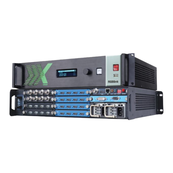
System Overview System Overview VENUS X2 is a multiple outputs video processor, it offers nine card cages that accepts a wide variety of video signals, including VGA, CVBS, S-HDMI, SDI and USB (for media files play). VENUS X2 combines truly... -
Page 21: Application Questions
1. Brief Introduction Application Questions Application Questions RGBlink offers solutions to demand technical problems. Any application questions, or required further information, please contact with our Customer Support Engineers. Refer to Appendix B for contact details. VENUS X2 User Manual... -
Page 22: Hardware Orientation
Hardware Orientation In This Chapter This chapter provides detailed information about the VENUS X2 hardware. The following topics are discussed: VENUS X2 Back Panel VENUS X2 Front Panel VENUS X2 User Manual... -
Page 23: Venus X2 Back Panel
1 preview output module slot Power module Input Module Slots VENUS X2 offers 4 input module slots, supports input signals including VGA, CVBS, S-HDMI, USB and SDI. Each VGA optional module includes 3 VGA inputs (DB15port), each CVBS optional includes 4 CVBS inputs (BNC... -
Page 24: 3G-Sdi Input
HDMI Output Connect to the display device, video processor or matrix. Preview Output Module Slot VENUS X2 offers 1 preview output module slots (VENUS X2 V1.4 can not support this function). Genlock Interface Includes 1 genlock input and 1 HDMI output. -
Page 25: 10/100M Udp Interface
10/100M UDP Interface Used to connect the windows control program or device upgrade. U-LINK In Interface Connect to the U-LINK output of the next VENUS X2, adopt 3.5mm analog audio interface, for multiple cascade. U-LINK OUT Interface Connect to the U-LINK input of the next VENUS X2, adopt 3.5mm analog audio interface, for multiple cascade. -
Page 26: Venus X2 Front Panel
2. Hardware Orientation VENUS X2 Front Panel VENUS X2 Front Panel Plug in the power cord, OLED module on the front panel will show as follows, user can operate VENUS X2 through the menus on OLED module. 维纳斯系列 VENUS SERIES X2 [>>... -
Page 27: Oled Panel
2. Hardware Orientation VENUS X2 Front Panel VENUS X2 front panel is as following: OLED Panel Used to show button menu and menus for interactive communication. USB Interface Used to device upgrade. Menu Button Used to adjust menu on OLED and for information interaction. Push the knob button to confirm current options. -
Page 28: Hardware Installation
Hardware Installation In This Chapter This chapter provides comprehensive installation instruction for VENUS X2 hardware. Following is the size of VENUS X2 for your reference. VENUS X2 User Manual... -
Page 29: Safety Precautions
Unpacking and Inspection Before opening VENUS X2 process shipping box, inspect it for damage. If you find any damage, notify the shipping carrier immediately for all claims adjustments. As you open the box, compare its contents against the packing slip. -
Page 30: Menu Orientation
Menu Orientation In This Chapter This chapter describes all VENUS X2 processor menus, including how they are accessed, the functions that are available, and descriptions of each menu tree (in block diagram format). The following topics are discussed: • MENU ... -
Page 31: Menu
Push the [MENU] button to go into the menu items, turn the knob button to select <RECALL>, show menus as follows: SCENE: VENUS X2 provides 16 scenes, users can save the current operation to SCENE 1 to SCENE 16. RECALL SAVE: It can recall the saved user modes via this function. -
Page 32: System
WIFI mode, user can choose STA or AP mode, and then scan the network, etc. FAN CONTROL: User can able or disable the auto speed function, and set the current speed. TIMER: User can set the timer power on and timer power off from Sunday VENUS X2 User Manual... -
Page 33: Language
FACTORY RESET Enter FACTORY RESET to reset the IP, choose YES and push the knob to confirm, then VENUS X2 is reset to its factory settings. It is ready for more operations after complete factory setting. VENUS X2... -
Page 34: Communication Software Guideline
Communication Software Guideline In This Chapter This chapter provides detailed information about the control communication software. The following topics are discussed: Software Installation Software Operation VENUS X2 User Manual... -
Page 35: Software Installation
Operating system: Windows 7 or above (full version, not Ghost version or compact version) Double click icon, it will pop-up the language choice box, choose the language, for example, choose ―English‖, and click ―OK‖ to confirm. Click ―Next‖ to install: VENUS X2 User Manual... - Page 36 Select ―Browse...‖ to choose the ROVA software install path: Note User should get the rights in ―Roles Management‖ when install the software to disk C if the system is Windows 7 or above. Click ―Install‖ to go on: VENUS X2 User Manual...
- Page 37 5. Communication Software Guideline Software Installation Click ―Finish‖ and ready to run ROVA windows control program: VENUS X2 User Manual...
-
Page 38: Software Operation
―Login‖. If user want to change the language to Chinese, click the drop down arrow after ―Language‖ and choose ―Chinese‖, as shown in the figure below, then click ―Login‖ to enter into the software. VENUS X2 User Manual... -
Page 39: Web Links
In the following parts, we will introduce these in detail. Web Links ROVA communication software sets up the web links. Click the web links shortcuts on the top left corner, and enter the company’s website, as shown in the figure below: VENUS X2 User Manual... -
Page 40: Connect The Device
Then, click the shortcut ―Search‖ on the operation interface. Then it will search the device, and show the device name, device number and IP after search, as shown in the figure below: Finally, click the device to connect, as shown in the figure below: VENUS X2 User Manual... -
Page 41: Output Settings
5. Communication Software Guideline Software Operation The software will automatically synchronize after connection, as shown in the figure below: Output Settings Click the ―Output Settings‖, and enter the interface as follows: VENUS X2 User Manual... - Page 42 Genlock: User can enable or disable the genlock function by sliding the genlock switch. If select ―ON‖, the output resolution will be same with the resolution that selected. HDMI or BNC can be selected in ―Input Source‖ by sliding the switch. VENUS X2 User Manual...
- Page 43 Click the ―Test Pattern‖, and pop-up window as follows: Output: User can select any board among the four boards. Color Choice: TP, colour bar and pure colour can be selected. Red, Green, Blue: If select ―Pure Colour‖, red, green and blue can be VENUS X2 User Manual...
- Page 44 Input Information: Input the information that will display in the box. Scrolling Speed: The scrolling speed can be set, and the adjustment range is between 1~16. OSD Scroll: Can select no scroll, left scroll and right scroll. Click ―Save‖ and ―Apply‖ after setting. VENUS X2 User Manual...
-
Page 45: Operation Mode
Click the ―Operation Mode‖, and enter the interface as follows: Videowall Mode, Matrix Mode and Presentation Mode are included in operation mode, specific as follows: Videowall Mode Click the ―Videowall Mode‖, and enter the interface as follows: Output Setting VENUS X2 User Manual... - Page 46 LCD Type: slide the monitor type switch, and select ―LCD Type‖. Besides H total, V total, row and column, user can custom the top border, bottom border, left border and right border in LCD type, as shown in the figure below: VENUS X2 User Manual...
- Page 47 Reset monitor: User can reset the monitor by clicking the shortcut the right side of the interface. Swap monitor: User can swap the monitor by clicking the shortcut the right side of the interface, as shown in the figure below. VENUS X2 User Manual...
- Page 48 1, as shown in the figure below: Rotation: Select the monitor, and set the rotation as 0° , 90° , 180° and 270° in the bottom of the interface. Click ―OK‖ to confirm. As shown in the figure below: VENUS X2 User Manual...
- Page 49 But this method can only adjust the size and location roughly, if an accurate adjustment is needed, the second method can VENUS X2 User Manual...
- Page 50 ‖ on the right side of the interface, the output area will be adjusted automatically. Property Setting: Select the layer to be adjusted, click the More shortcut ― ‖ in the bottom of the interface, and enter the interface as follows: VENUS X2 User Manual...
- Page 51 ―ON‖ for ―H.264 Display‖, as shown in the figure below: Then enter to the videowall mode, the bottom of the interface will display the H.264 video, as shown in the figure below, which is for preview. VENUS X2 User Manual...
- Page 52 Take The take interface is shown as the figure below: Set the alpha time, and the adjustment range is 0~10S. Slide the black scene switch to enable or disable the black function. Auto take VENUS X2 User Manual...
- Page 53 Select the input or output board to read and write the EDID. As shown in the figure below: Loop Click the loop shortcut ― ‖, and pop-up window as follows: VENUS X2 User Manual...
- Page 54 Load Script Click the load script shortcut ― ‖, and pop-up window as follows: User can load the data from the computer. Save Script Click the save script shortcut ―‖ , and pop-up window as follows: VENUS X2 User Manual...
- Page 55 Click the out card set shortcut ― ‖, and pop-up window as follows: Click any output, and pop-up window as follows: X, Y, width, height,rotate can be set. If click ―Advanced Setting‖, pop-up window as follow: VENUS X2 User Manual...
- Page 56 In advanced setting, scale and crop can be set. Not recommended to use “Advanced Setting”. Short Key Click the shortcut ― ‖, and pop-up window as follows: Use shortcut key to operate fast and easily. Matrix Mode Click the ―Matrix Mode‖, and pop-up window as follows: VENUS X2 User Manual...
- Page 57 Default source 1 to monitor 1, source 2 to monitor 2, and so on. Select the signal, and drag it to the source that will set. For example, set signal 3 for source 1, as shown in the figure below: VENUS X2 User Manual...
- Page 58 Select the preview mode, and select multiview or splice multiview, then select the preview image according to actual need. User can select max three outputs in one output card. The connection diagram area will show the corresponding splice guidance figure, as shown in the figure below: VENUS X2 User Manual...
-
Page 59: Input Settings
Click the ―Input Settings‖, and enter the interface as follows: DSK settings, source backup and source merge are included in input settings, specific as follows: DSK Settings Click the ―DSK Settings‖, and pop-up window as follows: VENUS X2 User Manual... - Page 60 , and set the backup signal for Hot Backup 1 to Hot Backup 8. It will switch to the backup signal if the signal is interrupted. Source Merge Click the ―Source Merge‖, and pop-up window as follows: VENUS X2 User Manual...
- Page 61 Click any layer, then click any source, and the layer source can be switched, as shown in the figure below: User can also scale or crop the layer. If image quality distorts by improper operation, it can be recover by reset. VENUS X2 User Manual...
-
Page 62: Access Control
Add: Input the user name and password, and select the user type as ―Admin’ or ―Users‖, click ―Add‖ after setting. Edit: Select the admin or users in user’s list, then edit the password or user type, click ―Edit‖ after setting. VENUS X2 User Manual... -
Page 63: System Settings
Detail‖. Click ―OK‖ after setting. User can operate the rights that selected. System Settings Click the ―System Settings‖, and enter the interface as follows: System information, IP settings, factory reset and streaming IP & power on settings are included in system settings, specific as follows: VENUS X2 User Manual... - Page 64 It takes effect after reboot the software if change IP through network. User do not need to set it if choose ―Auto get ip address‖. Factory Reset Click the ―Factory Reset‖, and pop-up window as follows: VENUS X2 User Manual...
- Page 65 H.264 video when enter to the operation mode, which is for preview. IP Address: Set the IP address of H.264 video, click ―Set‖ after setting. Time-Lapse Power On: The adjustment range is 0~255, click ―Set‖ after setting. VENUS X2 User Manual...
-
Page 66: Specification
1280×1024@60 I 1440×900@60 I 1600×1200@60 I 1920×1080@60) USB Input Module Interface Appearance 131.6(L)×20(W)(mm) Board Size Number of Inputs Connector Standard USB port Max Support 1920×1080@30 Resolution Supported Standard Support general Image and video formats S-HDMI Input Module Interface Appearance VENUS X2 User Manual... - Page 67 Balance 250m at 1.485Gb/s 480m at 270Mb/s HDMI Program Output Module Interface Appearance 131.6(L)×20(W)(mm) Board Size Number of Outputs Connector HDMI standard type A interface Supported Resolution SMPTE: 625/25 PAL, 525/29.97 NTSC, 625/50p PAL, 525/59.94p NTSC, VENUS X2 User Manual...
- Page 68 Support any two inputs fade in fade out Extras Communication Windows control program, TCP/IP Power Supply 100-240V IEC-3 Working Environment 0° C~45° C Stored Environment 10% to 90% Product Warranty 3 years parts and labor warranty VENUS X2 User Manual...
-
Page 69: Contact Information
All video products are designed and tested to the highest quality standard and backed by a full 3 years parts and labor warranty. Warranties are effective upon delivery date to customer and are non-transferable. RGBlink warranties are only valid to the original purchase/owner. Warranty related... -
Page 70: Software Upgrade
2. Plug into the power cord and make sure the VENUS X2 is in normal operation. 3. Plug the USB disk into the USB interface in the front panel of VENUS X2, the device will upgrade automatically. The buzzer sounds beeps during upgrade, the beeps will stop and the USB disk will delete the upgrade file automatically after complete upgrade. -
Page 71: Optional Module Installation And
VENUS X2 and VENUS X3 support replaceable input and output optional modules, user can install or replace the optional module according to actual need. The installation steps of VENUS X2 and VENUS X3 are the same. Here we take VENUS X3 for example, specific steps are as follows: Install the Optional Module 1. - Page 72 DVI input module: ② For the joined PCB input module with CVBS, HDMI, VGA, USB or SDI interface, fix the input module on the plate with 2 M3*4 flat screws and 2 M3*4 round head screws. VENUS X2 User Manual...
- Page 73 HDMI input module: VGA input module: CVBS input module: USB input module: 3. Fix the input module block with fixed screws, as shown in figure: VENUS X2 User Manual...
- Page 74 4. Push the input modules into the device along the slide rail, and screw the captive screws, as shown in figure: Note: The install steps of output module installation and input/output module replacement are the same as above. VENUS X2 User Manual...
Need help?
Do you have a question about the VENUS X2 and is the answer not in the manual?
Questions and answers