Sign In
Upload
Download
Table of Contents
Contents
Add to my manuals
Delete from my manuals
Share
URL of this page:
HTML Link:
Bookmark this page
Add
Manual will be automatically added to "My Manuals"
Print this page
×
Bookmark added
×
Added to my manuals
Manuals
Brands
Nikon Manuals
Measuring Instruments
DTM-502 Series
Instruction manual
Nikon DTM-502 Series Instruction Manual
Hide thumbs
1
2
3
4
5
6
7
8
9
10
11
12
13
14
15
16
17
18
19
20
21
22
23
24
25
26
27
28
29
30
31
32
33
34
35
36
37
38
39
40
41
42
43
44
45
46
47
48
49
50
51
52
53
54
55
56
57
58
59
60
61
62
63
64
65
66
67
68
69
70
71
72
73
74
75
76
77
78
79
80
81
82
83
84
85
86
87
88
89
90
91
92
93
94
95
96
97
98
99
100
101
102
103
104
105
106
107
108
109
110
111
112
113
114
115
116
117
118
119
120
121
122
123
124
125
126
127
128
129
130
131
132
133
134
135
136
137
138
139
140
141
142
143
144
145
146
147
148
149
150
151
152
153
154
155
156
157
158
159
160
161
162
163
164
165
166
167
168
169
170
171
172
173
174
175
176
177
178
179
180
181
182
183
184
185
186
187
188
189
190
191
192
193
194
195
196
197
198
199
200
201
page
of
201
Go
/
201
Contents
Table of Contents
Bookmarks
Table of Contents
Table of Contents
Read this Section before Use
Warning and Caution
Operation
Maintenance
Preparation
Unpacking and Packing the DTM-502
Setting up the Tripod
Centering
Leveling
Sighting
Assembling the Prism Reflector
Face-1/Face-2 Measurement
Table of Contents
Display and Key Functions
Basic Measurement Screen (BMS)
LCD Backlight, Reticle, LG, Sound and Contrast
Pre-Start
Input Point Name/Number
Inputting a New PT
Inputting an Existing PT
Pressing [ENT] Without a PT
When a Wildcard (*) Is Specified
When the [MSR] Softkey Is Pressed
Inputting PT by [List] Softkey
Inputting PT by [Stack] Softkey
Direct Input
How to Input a Code
Stack
Code List
Qcode
How to Input Feet-Inches
List Displays of Data/Jobs
About Jobs
Getting Started
Pwr
Turn on the Instrument [PWR]
Msr1 Msr2
Measuring Distances
Sighting a Prism Reflector
Settings for Measurement
Dsp
Changing Display
Switch Displays DSP
Customizing Items on the BMS
Mode Key [MODE]
While Inputting PT/CD
Quick Code Mode (from BMS)
COD Key [COD]
Qcode Observation
Updating Default CD
HOT Key [HOT]
Height of Target
Select Target-Set
Temperature & Pressure
Note
Level [Bubble]
Lumi-Guide On/Off [LG]
Ang
Applications
HA Reset and Angle Operations ANG
Input
Inputting the Horizontal Angle
Set
Setting the Horizontal Angle to 0
Recording a Foresight Point after Repeat Angle Measurement
Rept
F1/F2
Face1/Face2 Measurement
Hold
Horizontal Angle Hold
Stn
Instrument Station Setup STN
Known Stn
Station Setup with Known Coordinates or Azimuth
1: Known→1:Coord
Sighting the BS (Backsight) Point by Inputting Coordinates
1:Known→2:Angle
Sighting the BS (Backsight) Point by Inputting Azimuth Angle
Multiple Point Resection Setup Station by Angle/Distance Measurements to Known Points
Quick Station (Quick)
Setup the Station Quickly Without Given Coordinates
Remote Benchmark (RBM) Determine Station Elevation
Bscheck (Bschk)
Check and Reset the Backsight Direction
S-O
Ang-Dist (HD-HA)
Specifying the Stakeout Point Position by Angle and Distance
Stakeout S-O
Input XYZ
Specifying the Stakeout Point Position by Coordinates
Divline S-O
Refline S-O
Prg
Measuring Distance and Offset Values Along a Specified Line
Program Key [PRG]
Pt Reference Line
Arc-Curve Reference Line (Arc) Measuring Distance and Offset Values on the Arc-Curve
Measuring between the Current and the First Point Measured
RDM (Radial)
Remote Distance Measurement
Measuring between the Current Point and the Immediately Preceding Point
RDM (Cont.)
Remote Elevation Measurement
Pt Reference Plane (V-Pln) Measuring Distance and Offset Values on the Vertical Plane
Pt Reference Plane (S-Pln) Measuring Distance and Offset Values on the Slope
Rec/ Ent
Recording Data from any Observation Screen
Recording Measurement Data [REC/ ENT ]
Outputting Data to the COM Port
Offset Measurements O/S
Tape Offset Measurements
Angle-Offset Measurements
Two-Prism Pole
Line Extension by Horizontal Angle Offset
Horizontal Distance Input after Angle-Only Shot
Calculate the Corner Point
Circle Offset Measurements
Extend Slope Distance
USR Key [USR1]/ [USR2]
DAT Key DAT
Creating a New Job
Job Manager
Opening an Existing Job
Using Various Functions (Menu-Key) [MENU]
Deleting Job
Control Job
Displaying Job Information
Calculating Angle and Distance between Two Coordinates
Cogo
Coordinate Geometry Calculations
Inverse
Bearings & Distances Calculating Coordinates from Angle and Distance
Area & Perimeter Calculating Area and Perimeter
Calculating Coordinates from Line and Offset
Line and Offset
Input Coordinate Manually Input Coordinate
Menu
Initial Settings
Sett
Data
View Records
Viewing and Editing Records
Delete Record
Edit Records
Search Record
Input Coordinate
Name List and Code List
Communication
Download Data
Upload Coordinate Data
Upload PT-List/Code-List File
Sec-Keys
Settings in [MSR] Key
Settings in [DSP] Key
Settings in [USR] Key
Calibration
Settings in [DAT] Key
Settings in [S-O] Key
Date & Time
Operation
Advertisement
Quick Links
1
Operation
Download this manual
H162 E
02.10.VF.2
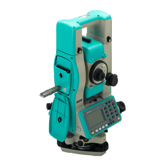
Total Station DTM-502 series
DTM-552
DTM-532
DTM-522
Instruction Manual
Table of
Contents
Previous
Page
Next
Page
1
2
3
4
5
Advertisement
Chapters
Table of Contents
25
Operation
158
Table of Contents
Need help?
Do you have a question about the DTM-502 Series and is the answer not in the manual?
Ask a question
Questions and answers
Subscribe to Our Youtube Channel
Related Manuals for Nikon DTM-502 Series
Measuring Instruments Nikon Total Station DTM-322 Instruction Manual
(185 pages)
Measuring Instruments Nikon HQA46480 Instruction Manual
(185 pages)
Measuring Instruments Nikon DTM-552 Instruction Manual
(201 pages)
Measuring Instruments Nikon DTM-532 Instruction Manual
(201 pages)
Measuring Instruments Nikon DTM-522 Instruction Manual
(201 pages)
Measuring Instruments Nikon DTM-350 Instruction Manual
Electronic total stations (191 pages)
Measuring Instruments Nikon DTM-330 Instruction Manual
Electronic total stations (191 pages)
Measuring Instruments Nikon Aculon Instruction Manual
(64 pages)
Measuring Instruments Nikon NPL-322 Instruction Manual
Total station (197 pages)
Measuring Instruments Nikon RifleHunter 550 Instruction Manual
Nikon laser rangefinder instruction manual (2 pages)
Measuring Instruments Nikon ProStaff LASER 440 Instruction Manual
(2 pages)
Measuring Instruments Nikon Nivo 2.C Instruction Manual
Hardware (32 pages)
Measuring Instruments Nikon Black Range X 4K Instruction Manual
(44 pages)
Measuring Instruments Nikon COOLSHOT Instruction Manual
(10 pages)
Measuring Instruments Nikon Arrow ID 3000 Instruction Manual
(36 pages)
Measuring Instruments Nikon Laser 800 - Monarch Laser 800 Rangefinder Instruction Manual
Instruction manual (8 pages)
This manual is also suitable for:
Dtm-552
Dtm-532
Dtm-522
Table of Contents
Print
Rename the bookmark
Delete bookmark?
Delete from my manuals?
Login
Sign In
OR
Sign in with Facebook
Sign in with Google
Upload manual
Upload from disk
Upload from URL


Need help?
Do you have a question about the DTM-502 Series and is the answer not in the manual?
Questions and answers