Table of Contents
Advertisement
Quick Links
Advertisement
Chapters
Table of Contents

Related Manuals for Nikon DTM-350


Summary of Contents for Nikon DTM-350
- Page 1 Electronic Total Stations DTM-350 Model DTM-330 Model Instruction Manual...
-
Page 2: Warning And Caution Symbols In This Manual
Thank you for purchasing the Nikon products. This instruction manual was written for the users of the Electronic Total Station DTM-350/330. To ensure correct usage read this manual carefully before operating the instrument. Also read the Instruction Manual provided with the Battery Charger and any other equipments used together with the DTM-350/330. -
Page 3: Read This Section Before Use
Never see the sun through the telescope. Doing so may cause the loss of your eyesight. The DTM-350/330 does not feature explosion-protected construction. Do not use in coal mines, in areas contaminated with coal dust, or near other flammable substances. - Page 4 WARNING AND CAUTION Read This Section Before Use! CAUTION The top of the tripod ferrule is very sharp and may injure your body. Be careful in handling or carrying the tripod. Check the shoulder strap and its clasp before carrying the tripod or the instrument encased in the carrying case.
-
Page 5: Maintenance
MAINTENANCE Read This Section Before Use! Avoid prolonged exposure to the sun or the heat of a closed vehicle. Efficiency could be adversely affected. If the instrument has been used in wet conditions, incline the instrument so as to remove the water drops out of the concave parts on the instrument. - Page 6 If you expose the carrying case to rain because of unavoidable circumstances, place it with its “Nikon” nameplate upward. The BC-65 battery pack holds Ni-MH inside. Be sure to follow the...
-
Page 7: Table Of Contents
Contents Warning and Caution Symbols in This Manual ....i Read This Section Before Use!..........ii WARNING AND CAUTION..............ii MAINTENANCE ..................iv 1. NOMENCLATURE ............1-1 2. PREPARATION............... 2-1 2-1 Unpacking and Packing the Instrument ........2-1 2-2 Recharging and Connecting the BC-65 Battery Pack....2-2 2-3 Setting up the Tripod.............. - Page 8 5. SPECIFICATIONS............5-1 5-1 Main Body ..................5-1 5-2 Standard Components ..............5-4 5-3 External Device Connection Connector ........5-4 6. SYSTEM DIAGRAM ............6-1 7. COMMUNICATIONS ............7-1 7-1 Upload Coordinate Data.............. 7-1 7-2 Uploading Code List..............7-3 7-3 Downloading Data............... 7-5 8.
-
Page 9: Nomenclature
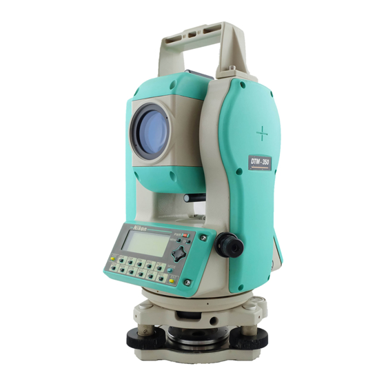
1. NOMENCLATURE Carrying handle Battery mounting button Telescope focusing ring Battery pack Telescope BC-65 eyepiece Vertical clamp Diopter ring Vertical tangent screw Reticle plate cover Plate level Upper plate clamp Display Upper plate Face-left keyboard tangent screw Refer to p.3-1, p.3-2 and p.3-3 for the key arrangement and its major function. - Page 10 Optical sight (Finder) Horizontal axis indication mark Objective Optical plummet Face-right keyboard Data output/ External power input connector Leveling base Input voltage DC 7.2 – 11V Circular level Leveling screw...
-
Page 12: Preparation
2. PREPARATION 2-1 Unpacking and Packing the Instrument Handle gently the instrument to guard against shocks or excessive vibration. Encase the instrument with the battery pack attached. Unpacking Hold the carrying-handle and take the instrument out of the case. The instrument is placed in its carrying case as shown in the figure. -
Page 13: Recharging And Connecting The Bc-65 Battery Pack
2-2 Recharging and Connecting the BC-65 Battery Pack WARNING Use only the specified charger Q-75U/E for charging the battery pack BC-65. Charging by the other types of chargers than specified may cause fire or rupture. (BC-65 can not be charged by using the charger Q-7U/E or Q-7C.) While recharging the battery pack, do not cover the charger with any blanket or clothing which can cause overheating. - Page 14 If the battery pack is recharged within the specified ambient temperature range and the charging indicator stays lit for 4 hours or longer, something is wrong. Contact your dealer or a Nikon representative. (If an ambient temperature lowers than 0°C while recharging the battery, the charger’s temperature sensor will stop the...
- Page 15 Recharging Procedure (1) Insert the power plug of charger into To AC outlet an AC outlet. Charging indicator (2) Connect the charging plug to the Disharging indicator battery pack’s charging connector. Disharging starting (3) Quick charging will then start switch automatically.
- Page 16 (1) Depress the battery mounting button while holding the battery pack. An external battery (optional accessory) is available for use with the DTM-350/330. When the external battery is connected and the battery pack BC-65 is mounted on the instrument, its electrical source will automatically be switched to the one with the higher battery power.
-
Page 17: Setting Up The Tripod
2-3 Setting up the Tripod CAUTION The top of the tripod ferrule is very sharp and may injure your body. Be careful in handling or carrying the tripod. (1) Open the tripod legs sufficiently enough for the instrument to be stable. (2) Assure that the station point is located directly beneath the center hole in the tripod head. -
Page 18: Centering
2-4 Centering “Centering” refers to the precise alignment of the instrument’s central axis over the station point. This can be accomplished in two ways, through the use of a plumb bob, or the optical plummet. Using Plumb Bob (1) Place the instrument on the tripod head. Insert the tripod mounting screw into the center hole of the instrument’s base plate and tighten. - Page 19 Using Optical Plummet Carry out the “CHECKING AND ADJUSTMENT of Optical Plummet” (p.4-2) when the centering operation is performed at a position higher than the station point. For high accuracy, carry out the “CHECKING AND ADJUSTMENT of Optical Plummet” (p.4-2) before the centering operation. (1) Place the instrument on the tripod head.
-
Page 20: Leveling
2-5 Leveling “Leveling” refers to the precise vertical alignment of the instrument’s vertical axis. The procedure for leveling by means of the plate level is described below. (1) Loosen the upper plate clamp. Rotate the alidade to position the plate level to a point parallel with any two of the leveling screws B and C (See Figure). -
Page 21: Sighting
2-6 Sighting “Sighting” refers to the aiming of the telescope at the target, bringing the target image into focus, and aligning it with the center crosshairs of the reticle. WARNING Never view the sun through the telescope. Doing so may cause the loss of your eyesight. -
Page 22: Assembling The Prism Reflector
Slide the prism holder mount to align the height Height adjustment screw adjustment screw holes and screw in the adjustment screw again. When using the DTM-350/330, set the prism holder mount to the lower position. 2-11... - Page 23 Attach the prism to the single prism holder or triple prism holder. The prism constant of Nikon prism is 0, regardless of the prism holder type. The triple prism holder can also be used as a single prism holder if one prism is screwed in the center thread of the triple prism holder.
-
Page 24: Face-Left/Face-Right Measurement
2-8 Face-left/Face-right Measurement Face-left Measurement: Measurements made with the vertical circle positioned to the left of the telescope eyepiece Face-right Measurement: Measurements made with the vertical circle positioned to the right of the telescope eyepiece Be careful not to catch your finger in the opening between the instrument’s standard and the telescope when rotating the telescope. - Page 25 CONTENTS 3 OPERATION................3-1 3-1 DISPLAY AND KEY FUNCTIONS ..........3-1 Basic Measurement Screen (BMS)..........3-4 3-2 PRE-START ................... 3-5 Input Point Name/Number.............. 3-5 1) Pressing the [ENT] without a PT ............3-5 2) Inputting a new PT ................3-6 3) Inputting a known PT ................. 3-6 4) When a wildcard (*) is specified............
- Page 26 MODE Mode Key ..................3-23 1) While Inputting PT/CD ..............3-23 2) Quick Code Mode (from BMS) ............3-24 HOT Key ..................3-25 ○ 1) Height of Target ................3-25 2) Temperature & Pressure ..............3-25 3) MSR/TRK Key Settings..............3-25 4) Level....................
- Page 27 Staking out ..................3-49 ○ 1) Ang-Dist (HD-HA) ................3-49 2) XYZ ....................3-52 3) 2-Pt Reference Line (2REF) .............. 3-56 4) 2-Pt Reference Plane (V-Pln) ............3-58 5) 3-Pt Reference Plane (S-Pln)............. 3-60 6) Arc-curve Reference Line (Arc)............3-62 Recording Measurement Data............
- Page 28 4) Data....................3-95 4-1) Display Records ................. 3-95 4-2) Delete Record................3-99 4-3) Edit Record ................3-101 4-4) Search Record................3-104 4-5) Input Coordinate ..............3-108 4-6) Code List.................. 3-109 5) Communication ................3-115 5-1) Download Data ................ 3-115 5-2) Upload Coordinate Data ............3-116 5-3) Upload List File...............
-
Page 29: Operation
3. OPERATION Display and Key Functions Illumination Key Turns ON/OFF the display Back-light. Holding down for one second will show a screen to adjust: 1.Backlight, 2.Sound Battery Voltage Level Indication Indicates the battery level in five steps. (See p.3-4) Input Mode Indication Indicates the input key mode ( ) during input PT or CD input. - Page 30 Summary detail p.3-14 Turns the Power ON and OFF. p.3-28 Turns the Backlight ON and OFF. When held down for over one second, it shows a setting screen for: 1:Backlight, 2:Sound ON/OFF. p.3-78 Displays MENU items: 1:JOB, 2:COGO, 3:Sett, 4:Data, MENU 5:Comm., 6:Time, 7:Calib.
- Page 31 In the alpha-numeric input mode ( ), enters *, /, =, 0. Proceeds to next screen. In the numeric or alpha-numeric input mode, accepts the input data. Also, on the BMS, outputs the current measurement data ○ (Pt/HA/VA/SD) via COM port when “Ext.Comms=Nikon” is set.
-
Page 32: Basic Measurement Screen (Bms)
Basic Measurement Screen (BMS) HA:123° 45’50” Status bar VA: 90° 15’50” SDx 1231.008 m DSP1/4 : Level 4 (Full) 1) Battery : Level 3 : Level 2 : Level 1 : Battery LOW !Battery Down : Battery Change Press ENT key Change... -
Page 33: Pre-Start
Pre-Start Input Point Name/Number You can use point numbers or names up to 12 digits in length. When the system gives you a default PT, basically, the Last recorded PT + 1 is used, except the case where the last digit is alphabet. For coordinate records, you cannot use a point name/number that already exists in the current Job except when you record sideshots or stakeout shots. -
Page 34: Inputting A New Pt
2) Inputting a new PT When you input a new point name/ PT:55 X:-154. 231 ■ number, it shows a coordinate input Y: screen right. You can input a 2D Z: “NE(EN)”, 3D “NEZ(ENZ)”, or elevation only “Z” coordinate. Press the [ENT] key on the last line (Z:field) to store the point in the current Job. -
Page 35: When A Wildcard (*) Is Specified
4) When a wildcard (*) is specified A list of available points are displayed Input 1st Point when you use an asterisk to input PT or PT: HT: 1. 5000m CD:FENCE* ■ Use the up/down arrow keys and [ENT] to [ENT] select the point you want to use. -
Page 36: How To Input A Code
How to input a Code Basically, CD: field is defaulted to the code previously used. You can change it on the recording point screen. 1) Manual Input Press the [Mode] key to change the input PT:10006 mode into alpha-numeric (A) or numeric HT:... -
Page 37: Code List
3) Code List Press the [Lst] key to display a feature PT:10053-A10 code List. It shows the first four codes HT: 1.6050m CD:CURB from the first layer. Lst O/S Qcd Stk To edit the Code List, you can go into MENU/4:Data/3:Code List. -
Page 38: Qcode
================== Advanced Functionalities ================== The First character Search in List For instance, when you want to see the >BACK feature code begins with “T”, you can BUILDING S just hit [7] key twice, while it shows a CURB List. DUOMO ↓... -
Page 39: How To Input The Feet-Inches On The Instruments
How to Input the Feet-Inches on the Instruments When either US Survey Feet (US-Ft) or International Feet (I-Ft) is selected as the distance unit, there is an option for values to be input and displayed in decimal feet, or in feet and inches (See p.3-93). All distances, HI’s, HT’s and coordinate values will be entered and displayed in feet and inches. -
Page 40: List Displays
List Displays You will see the same type of “list” display in View/Edit data (MENU/4:Data), Code List function, Qcode Edit (HOT/5:Qedit), and Job manager (MENU/1:JOB). There are some common rules to operate this “list”. “>” on the first line shows the current >UP,502... -
Page 41: About Jobs
About Jobs When you record data on the instrument, you must create or open a Job. Up to 8100 records can be stored to one Job database. You can have a maximum of eight Jobs at one time. (See p.3-78 for detail) Please check the settings first when you use the instrument for the first time. -
Page 42: Getting Started
Getting Started Turn On the Instrument Press the [PWR] key to turn on the TILT TELESCOPE instrument. The start-up screen shown >Temp 20°C Press 1013hPa right appears. 2000-07-17 11:35 The current Temperature and Pressure are displayed. The displayed value can be modified on TILT... - Page 43 Rotating the alidade before tilting the HA INITIALIZED >Temp 20° C telescope initializes the HA. Press 1013hPa 2000-07-17 11:35 ・When the telescope is tilted before rotating the instrument, the horizontal angle is not initialized. Instead, it simply recalls the last HA reading before Power OFF.
-
Page 44: Turn Off The Instrument
Turn Off the Instrument ○ Press [PWR] and [ENT] to turn off the instrument. Press ENT →OFF Rst Save [2:Rst]=re-boots the program and starts over. [4:Save]=puts the instrument into sleep mode. [ESC]=cancels the power-off process and returns to the previous screen. -
Page 45: Measuring Distances
Measuring Distances ○ ○ 1) Sighting a prism reflector WARNING Never view the sun through the telescope. Doing so may cause loss of eyesight. Sighting a single prism Sight the telescope crosshairs on the center of the prism reflector. When reflected light is detected, the signal level is indicated. -
Page 46: Measuring Distances
2) Measuring distances Press the [MSR] or [TRK] key on the HA: 90°15’50” VA:123°45’50” BMS or any other observation screens to SDx 1241.008 m take a measurement. DSP1/4 When the Average count is set to 0, measurements are taken continuously until [MSR]/[TRK] or [ESC] is pressed. -
Page 47: Measurement Mode Settings
3) Measurement mode settings Holding down the [MSR] or [TRK] key >Target :Prism for one second shows the measurement Const : 30mm settings for each key. Mode :Prec AVE :2 Move the cursor by the up/down arrow keys and use the right/left arrow keys to change the setting. - Page 48 Switching between Screens ○ 1) Changing display 1/4 screen Press the [DSP] key to change the HA: 90°15’50” VA:123°45’50” contents of the screen on the Basic SD: 284.563 m Measurement Screen (BMS). DSP1/4 Upon each press of the [DSP] key, the 2/4 screen screen scrolls among DSP1/4 to 4/4.
- Page 49 2) Customizing items on the BMS Holding down the [DSP] key for one HA: 90°15’50” VA:123°45’50” second to customize the screen on the SD: 284.563 m BMS. DSP1/4 DSP1/4, DSP2/4, and DSP3/4 can be [DSP] for 1 sec. edited to show the desired items. (*) Select...
- Page 50 = Header characters = ・ The ":" character indicates that Tilt correction is applied. ・ The "#" character indicates that Tilt adjustment is set to OFF. ・ The "_" character under the Tilt correction character indicates that Sea Level Correction is applied. HA:...
-
Page 51: Mode
MODE Mode key The [Mode] key changes the the keyboard mode depending on the current screen. 1) While Inputting PT/CD Pressing the [Mode] key while the cursor Input Point is in the PT field changes the input mode PT:1 CD:FENCE2 ■ between Alpha-numeric (A) and Numeric (1). -
Page 52: Quick Code Mode (From Bms)
2) Quick Code Mode (from BMS) When you press the [Mode] key on the HA:316° 50’40” VA: 91° 25’35” BMS, it activates the Quick code SD: 150.687 m measurement mode. (See p.3-65) DSP1/4 [Mode] A default point name is displayed on the HA:316°... -
Page 53: Hot Key
HOT key ○ The [HOT] key is available from any 1 :HT 5:Qedit observation screen. It shows the screen 2:T-P 6:Qmode 3:Meas. on the right. 4:Level Press the [ESC] key to return to the previous screen. 1) Height of Target Input... -
Page 54: Level
The leveling indication is displayed automatically on any measuring screen if the instrument goes out of level while the compensators are turned on. It can also be displayed by pressing the [HOT] and [4] keys. <DTM-350 = 2axis compensation> :-0’05” You can turn the leveling compensators :... -
Page 55: Qmode
6) Qmode This function defines the setting for Qcode Modes >Confirm :Yes Qcode mode. Meas mode:MSR Confirm: “Yes” = displays the point input screen to confirm PT/HT/CD before recording each measurement. “No” = skips the point input screen and directly stores the point after a measurement. -
Page 56: Lcd Backlight And Sound On/Off
LCD Backlight Sound On/Off . 2. The LCD backlight can be turned ON/OFF by pressing the illumination key. Holding down the illumination key for one second activates the Backlight and Sound ON/OFF switches from any observation screen. Use the Right/Left arrow keys to turn the switch ON/OFF. The Up/Down arrow keys and the numeric keys can be used to move the cursor between the item 1 and 2. -
Page 57: Simple Station Input (Xyz-Key)
Simple Station input (XYZ-key) / ○ = The [XYZ] key is a simple and conventional way of setup. 1) Input the station coordinate 2) Set the horizontal angle by [ANG] key ※No ST record is stored to the DB in this function. Therefore, when you try to record data to an open job after using this key, your SS/CP records follow a comment record (CO, STN is changed by [XYZ] key) instead of ST. -
Page 58: Applications
Applications HA Reset and Measurements ○ Perform face-left and face-right measurements to obtain maximum accuracy for measuring angles. (Refer to p.2-15) By doing so, mechanical constant error (except in some special cases such as the vertical axis error) can be effectively cancelled out. Press the [ANG] key to display the angle HA:120°... - Page 59 3)Hold Horizontal Angle Hold HA: 65° 10’00” Press the [3] key to hold the horizontal - HA Hold - angle to the current value. Abrt Set Press the [4:Set] or [ENT] key to set the horizontal angle as it is displayed. After setting the angle, it returns to the basic measurement screen.
- Page 60 5)Rept. Recording a foresight point after repeat angle measurement Press the [4] key to display “0” as a HRΣ 0° 00’00” - HR Hold - horizontal angle and activate repeat angle measurement mode. ANG N= 0 Press the [ENT] key to accumulate the HRΣ...
- Page 61 ・In this mode, the display “:” following “HA” is replaced with “Σ” and the number of repeat angles is displayed after “N=”. ・Horizontal angles can be measured up to 1999º59’59”. ・This function will store both RAW and XYZ data (as CP record) after the foresight point is measured regardless of the “Store DB”...
-
Page 62: Remote Distance Measurement
Remote Distance Measurement ○ Measures the horizontal distance, vertical distance and slope distance between two points. 2nd sighting point 1st sighting point Horizontal angle 0 direction 2nd sighting point rSD :Slope distance between two points rHD :Horizontal distance between two points 1st sighting rVD : Vertical distance between two points point... - Page 63 Cont Measuring between the current point and the immediately preceding point 2: Radial Measuring between the current point and the first point measured The screen shown right appears by rSD: m selecting 1 or 2 in the RDM menu. Sight rVD:...
-
Page 64: Remote Elevation Measurement
Remote Elevation Measurement ○ A prism is required only at Arbitrary point the sighting (target) point as a reference point. Θ Sighting point Station point Vh = HD・tan(90°-Θ) – VD + HT Press the [REM] key to display the screen HT:... -
Page 65: Instrument Station Setup
Instrument Station Setup ○ Press the [STN] key to display the menu Station Setup 1:Known 4:RBM 1 screen. 2:Resec 5:BSChk 3:Quick 1:Known Station setup with known coordinates or azimuth Press the [1] key to display the screen ST: ■ shown right. Input the station point HI:... - Page 66 → 1: Known 1:Coord Sighting the BS (backsight) point by inputting coordinates Backsight point (Xb, Yb, Zb) Station point (Xi, Yi, Zi) Input BS Point Press the [1] key to display the screen for PT: ■ inputting the BS point name and Height of HT:...
- Page 67 When you take a distance measurement to Sight BS on F2 AZ:123°45’50” the BS on FACE1, you can go to the HD: 87.9577m FACE2 measurement by just flipping the STN1/2 telescope. [ENT]/[REC] dHA: 0°00’21” After taking measurements on both faces, dVA:...
- Page 68 The screen for inputting the azimuth to the Input BS Angle BS point is displayed. Just pressing the AZ: ■ 1 [ENT] key inputs 0 º00’00” . Ex.) To enter 123º45’50”, key input should be 123.4550. Sight the BS point and press the [ENT] Sight...
-
Page 69: Multiple Resection
2: Multiple Resection Setup station by angle/distance measurements to known PT - Maximum 10 points can be used in Resection. - Calculation starts automatically when enough measurements are taken. - Deleting any poor observation data can be done. - Selecting BS point is available. Known point 1 (X1, Y1, Z1) Known point 2... - Page 70 Input the target height and press the Input 1st Point [ENT] key. When the coordinate is input PT:55 1 HT: 1. 5000 m manually on the previous screen, CD: can CD:CP1 be input on the screen. (Lst/Stk input are not available on this screen.) Sight...
- Page 71 Once the data enough to calculate the σN: 0.0193 Station coordinates are obtained, its σE: 0.0084 σZ: 0.0270 standard deviation screen will be Add DSP View REC displayed. Press [ESC] to return to the last [2:DSP] [2:DSP] measurement screen. N: 280.4193...
- Page 72 ================== Advanced Functionalities ================== View&Delete each data in Resection By pressing [3:View] key on the >45,CP1 37A,CP2 calculated STN data screen, you can 111,POLE/CT check your observation to each direction. [ENT] [ESC] dHA : distributed errors in HA to each direction PT:45...
- Page 73 Input the height of instrument and press ST:250 HI: 0.0000 m the [ENT] key. CD: “ST” is defaulted to the “Last recorded PT + 1”. You can change it if necessary. After inputting the ST, HI and CD for Select BS PT >55,CP1...
-
Page 74: Quick Station (Quick)
3: Quick Station (Quick) Setup the station quickly without given coordinates ST:1507 Press the [4] key on the setup menu to HI: 0.0000 m display the screen for inputting a quick BS: station point. AZ: 0.0000g ST : Station point (defaulted to the Last recorded PT +1) H I : Height of Instrument BS : Backsight point AZ : Backsight azimuth (defaulted to zero) -
Page 75: Remote Benchmark (Rbm)
4: Remote Benchmark (RBM) Determine the station elevation Input the BM point and press the [ENT] Input BM Point PT:■ key. When the point is found in the HT: 2. 1400m current or specified Control Job, it is CD: displayed. Sight... -
Page 76: Bs Check (Bs Chk)
5: BSCheck (BSChk) Check the Backsight direction Press the [5:BSChk] on the station setup HA:103° 50’34” 0 menu to enter the BS check function. BS:103° 50’30” 5 Abrt Rst Sight the BS and press the [ENT] or [4] key to reset the horizontal angle to the HA set in the last station setup. -
Page 77: Staking Out
Staking out ○ FILL Height of target FILL Press the [S-O] key to display the stakeout Stakeout 1 1:HD-HA 4:V-Pln menu screen*. Select the desired function 2:XYZ 5:S-Pln using the numeric keys. 3:2REF 6:Arc 1:Ang-Dist (HD-HA) Specifying the stakeout point position by Angle and Distance Press the [1] key to display the screen for HD:... - Page 78 When the [ENT] key is pressed without HA input, the current HA is input automatically. Rotate the instrument until the dHA dHA→ 35° 12’30” HD: 25. 356 m becomes close to 0º00’00”. Press MSRorTRK Sight the target and press the [MSR] or S-O...
- Page 79 Switching screen by [DSP] When the Secondary unit is set, one more screen (S-O9/9) is added. S-O3/8 S-O4/8 S-O5/8 S-O6/8 S-O1/8 S-O2/8 S-O7/8 S-O8/8 d HA← R ← rSD: R ← rVD: OUT← OUT↑ CUT↑ rHD: * S-O3/8, S-O4/8 and S-O5/8 can be customized by holding down [DSP] key for one second.
-
Page 80: Xyz
2:XYZ Specifying the stakeout point position by Coordinates Press the [2] key on the Stakeout menu PT:50* screen to start Stakeout by Coordinates. CD: 1 R: 50 ■ m Input the point number/name you want to stake and press [ENT]. You can also specify the points by Code and/or Radius from the instrument. - Page 81 Advise the rodman to adjust the prism dHA← 0°00’05” position. When the target is on the R ← 0.001 m intended position, the displayed errors OUT↑ 0.006 m become 0.0000 m/ft. PT:502 dHA: Difference in Horizontal angle to the target point R/L: Right/Left (Lateral error) IN/OUT: In/Out (Longitudinal error) Switching screen by [DSP]...
- Page 82 Press the [REC] or [ENT] key record the Input S-O Point point. A default PT is shown based on the PT:1002 ■ CD: previously recorded point number plus Lst Stk “Add constant” (See p.3-92). “Add Constant” is defaulted to 1000 in MENU/3:Sett/ 7:S-O. (See p.3-92) It requires an integer that is added to the point number being staked to obtain a new number for the staked point record.
- Page 83 ================== Advanced Functionalities ===================== Specify a Stakeout List by Range-Input Press the [MODE] key twice while PT: CD:s the cursor is in the PT field to show R: m the [Pts] softkey. PTs Input the start point (Fr) and the end PT...
-
Page 84: 2-Pt Reference Line (2Ref)
3: 2-Pt Reference Line (2REF) Measuring distance and offset values along a specified line Press the [3] key on the Stakeout menu Input Line PT1 screen to start 2-Pt Reference Line. P1: ■ P2: Input the two point names for the reference line. - Page 85 When the [HOT] key is pressed on any of the shooting point displays, it shows the setting screen. You can change the HT, T-P or Prism constant at any time. Switching screen by [DSP] When the Secondary unit is set, one more screen (REF5/5) is added. REF1/4 REF2/4 REF3/4...
-
Page 86: 2-Pt Reference Plane (V-Pln)
4: 2-Pt Reference Plane (V-Pln) Measuring distance and offset values on the vertical plane baseline Press the [4] key on the Stakeout menu Input Plane PT1 screen to start 2-Pt Reference Plane. P1: ■ P2: Input two points to define the plane. Inputting point by measurement is also Sight... - Page 87 Switching screen by [DSP] PLN1/3 PLN2/3 PLN3/3 Sta: To record the point, press the [REC] key Input Point PT:30123-A48 on any of the PLN1/3 to PLN3/3 screens. CD:BLD5 Input the feature code = Sample recording data in S-O/4:V-Pln = CO,Vertical Ref Plane Pt1:516-A1 Pt2:530 CO,Sta=68.021 dz=17.459 SS,30123-A48,1.5480,16.4020,40.4720,89.0730,14:22:47, 3-59...
- Page 88 5: 3-Pt Reference Plane (S-Pln) Measuring distance and offset values on the slope Target (X,Y,Z) Press the [5] key on the Stakeout menu P1: screen to start 3-Pt Reference Plane. P2: P3: Input three points to define the slope. Inputting point by measurement is also Sight...
- Page 89 In case the plane is defined by two (Temp P3) points (by selecting [1:Done]), that vertical plane will be the same with the one used in V-Pln function but the indicating factors (Sta/dZ vs a/b) are different. (See p.3-56) ・ Once the plane is defined, the calculated a:...
- Page 90 6: Arc-curve Reference Line (Arc) Measuring distance and offset values on the arc-curve Input the Start of the Curve point (P1) and Start of curve the azimuth of the tangent line (AZ1). P1:583 AZ1:35.4030 ■ P1can be input through measuring to a point by pressing the [Mode] key while the cursor is on the P1 field.
- Page 91 After you define the arc, the calculated Rad: 50.0000m Len: 125.6637m curve data will be shown for your AZ2:120°00′30″ confirmation. Abrt OK When the input value in “Rad” doesn’t match the one in “Len”, the system uses [4]/[ENT] the input “Rad” value and the “Len” will be replaced by the calculated value.
-
Page 92: Recording Measurement Data
. Recording Measurement Data - - ○ + ・ 1) Recording data from any observation screen Press the [REC] key to display the PT:10005 PT/HT/CD input screen right. HT: 1. 507 m CD:MANHOLE Lst O/S Qcd Stk You can quickly input frequently used feature codes using the Code List (Lst) and Code Stack (Stk) functions. -
Page 93: Qcode
2) Qcode Quick measurement & recording by less key-press HA:316° 50’40” To activate the Qcode mode, press [Mode] VA: 91° 25’35” SD: 150. 687m on the BMS. DSP1/4 [Mode] The default PT is shown in the bottom line. HA:316° 50’40” VA:... - Page 94 Assign a Code for Qcode To assign a new code to one of the PT:10053-A10 numeric softkeys, press [3:Qcd] on the HT: 1.247 m A CD:CURB ■ recording point screen after you edit the code. [Mode] PT:10053-A10 HT: 1. 247 m CD:CURB...
-
Page 95: Offset Measurements
3) Offset Measurements 3-1) Tape Offset Measurements PT:10053-A10 After a distance measurement to a point, HT: 1.605 m offset measurement is available when you CD:CURB press the [REC] key. Lst O/S Qcd Stk 1:Tape 5:Cnr Press [2:O/S] and [1] key to enter the 2:Angle... -
Page 96: 3-2) Angle-Offset Measurements
3-2) Angle-Offset Measurements After a distance measurement, press the 1:Tape 5:Cnr 2:Angle 6:+SD 2 [REC] and [2:O/S] to show the Offset 3:Pole 7:Circl menu screen. 4:+Line Select [2] key to enter the angle-offset. The current reading of HA/VA is shown. Angle... -
Page 97: 3-3) Two-Prism Pole Offset Measurements
3-3) Two-Prism Pole Offset Measurements After a distance measurement to the first 1:Tape 5:Cnr prism on the pole, press the [REC], 2:Angle 6:+SD 3 3:Pole 7:Circl [2:O/S] and [3:Pole] to get to the two- 4:+Line prism pole measurement. Input the distance between the second Input... -
Page 98: 3-4) Line Extension By Horizontal Angle Offset
3-4) Line extension by Horizontal Angle Offset After a distance measurement to the first 1:Tape 5:Cnr 2:Angle 6:+SD prism (or target) on the line, press the 3:Pole 7:Circl [REC], [2:O/S] and [4:+Line] to get to the 4 4:+Line Line Extension (by HA) function. Sight the second prism (or target) and Sight... - Page 99 = Example of recorded RAW data from [O/S]/4: +Line = SS, 40, 0.0000, 48.3304, 169.20370, 82.02470, 10:52:37 CO, PT1, 0.0000, 48.3020,169.19165, 83.58565 CO, PT2, 0.0000, 48.3155,168.54250, 85.42440 CO, O/S MSR:40 0.0000 169.20370 87.02340 * The calculated point (TGT) is stored as a SS record on the first line. * Measurements to the first and second target (P1 and P2) are stored as PT1 and PT2.
-
Page 100: 3-5) Corner Offset Measurements
3-5) Corner Offset Measurements After a distance measurement to the first 5 1:Tape 5:Cnr 2:Angle 6:+SD prism (or target) on the wall, press the 3:Pole 7:Circl [REC], [2:O/S] and [5:Cnr] to get to the 4:+Line Corner function. Sight the second point on the same wall Sight... - Page 101 When a measurement is taken to the forth Sight PT4 point, the corner point can be calculated HA:157°30’24” HD: 32.856 m as the intersection of two walls (P1-P2 REC and P3-P4). The default elevation is given by P4. Input the Code if necessary. The height of PT:58...
-
Page 102: 3-6) Slope Distance Extension
3-6) Slope distance extension After a distance measurement to a point, 1:Tape 5:Cnr press the [REC], [2:O/S] and [6:+SD] to 2:Angle 6:+SD 6 3:Pole 7:Circl input the additional slope distance 4:+Line manually. The measured distance is shown the Input Distance second line. -
Page 103: 3-7) Circle Offset Measurements
1:Tape 5:Cnr 3-7) Circle Offset Measurements 2:Angle 6:+SD 3:Pole 7 7:Circl 4:+Line After a distance measurement to the surface of the circle, press the [REC], [2:O/S] and [7:Circl] to get to the Circle offset function. Sight Edge1 HA: 47°05’35” Sight one edge of the circle and press Press... - Page 104 = Example of recorded RAW data from [O/S]/7: Circl = SS,71,1.5000,37.0518,32.08380,81.06510,11:51:48, CO, PT1, 0.0000, 0.0000,47.05350, 83.58560 CO, PT2, 0.0000, 0.0000, 29.53010, 83.58560 CO,O/S MSR:71 36.5418 38.28360 81.06510 CO,Input +SD:0.0020 * The calculated center point is stored as a SS record on the first line. * The following one or two comment lines are the observed points for the calculation.
-
Page 105: 3-8) Horizontal Distance Input After Angle-Only Shot
3-8) Horizontal distance input after Angle-only shot Turn the telescope to the direction of the HA:157°30’24” point and press [REC]. VA: 93°45’18” SD: m DSP1/4 [REC] [ESC] Input the code if necessary. Press [2:HD] PT:1462 to proceed to the horizontal distance HT:... -
Page 106: Menu
MENU Using Various Functions (menu-key) Press the [MENU] key to display the MENU screen. 1) Job Manager Press the [1] key on the MENU screen to 1:Job 5:Comms 2:Cogo 6:Time get into the Job Manager. It shows a Job 3:Sett 7:Calib... -
Page 107: 1-2) Creating A New Job
1-2) Creating a New Job Press the [MENU] key on the Job list Create 2 DEL screen to display the sub-function menu in 3 Control Job Manager. 4 Info Press the [1] or [ENT] key to show the Input JOB name “Input Job name”... - Page 108 Angle unit: DEG/GON/MIL >Angle :DEG Dist unit: Metre/Ft-US/Ft-Int Dist :Metre Temp :degC Temp unit: degC/degF Press :hPa ↓ Press unit: hPa/mmHg/inHg US-Ft or I-Ft For Feet users, there is an option to display and input values in Feet-Inch. Input /Displ ay After the “Dist:”...
-
Page 109: 1-3) Deleting Job
1-3) Deleting Job On the Job list screen, move the cursor to MENU for option the Job you want to delete. >*TOKYO10 NEWYORK3 @ Then, press the [MENU] key to display !TEST―A56 ↓ the sub-function menu. 1 Create Select [2:DEL] by pressing the [2] key. DEL... -
Page 110: 1-4) Control Job
1-4) Control Job A Control Job stores survey data (such as control points) that may be used by several jobs as the source of common data. This facility saves time when surveying a region that already has known points. Once a Control job is assigned, the system will search the coordinate points in the Control Job when the input point cannot be found in the current Job. -
Page 111: 1-5) Displaying Job Information
・When a Control Job is already assigned, the newly assigned Control Job replaces the previously assigned Control Job. ・To cancel the current control job, Terminate TEST―A55 move the cursor to the job name and as Control Job? press [MENU] and [3:Control] No... -
Page 112: Cogo
2) Cogo Coordinate Geometry Calculations Press the [2] key on the MENU screen to Cogo 1:PT-PT 4:Line display the COGO menu screen. 2:HA+HD 5:Input This function can be used at any time 3:Area from observation or inputting PT screens. 2-1) PT-PT Inverse Calculating Angle and Distance between two Coordinates Press the [1] key in the COGO menu to Input... -
Page 113: 2-2) Ha+Hd Coordinate
Press the [DSP] key to change the Gd: 6.20:1 V%: 10. 500 % contents of the result screen. rSD: 144. 6722m COGO2/2 Gd: Grade (HD/VD) V%: 100/Gd rSD: Slope distance PT1 to PT2 2-2) HA+HD Coordinate Calculating Coordinates from Angle and Distance Press the [2] key in the COGO menu to Input... -
Page 114: 2-3) Area & Perimeter
2-3) Area & Perimeter Calculating Area and Perimeter Press the [3] key in the COGO menu. Input the first point of the lot and press the Input Point 01 [ENT] key. In the upper right corner of PT:1005 ■ the screen, there is a counter to show how many points you have entered. -
Page 115: 2-4) Line And Offset
2-4) Line and Offset Calculating coordinates from Line and Offset Press the [4] key in the COGO menu to Line Define enter the Line & offset function. P1:100 ■ AZ: Type in the base point (P1) and specify the P2: bearing through P1 by either AZ or P2. -
Page 116: 2-5) Input Coordinate
The coordinate is stored as a CC record. -REC XYZ- Line definition info. and “Sta”, “O/S” and “dVD” values will be stored as comment Job:AMS-B66 records as well. 2-5) Input Coordinate Manually input coordinate Press the [5] key in the COGO menu to Input... -
Page 117: Sett
3) Sett Initial settings 1:Angle 5:Unit 1 2:Dist 6:Comm. Press the [3] key on the MENU screen to 3:Coord.7:S-O display the initial settings menu. 4:Power 8:Other ・The items shown in a box (ex. VA zero direction ) in “Conditions” column are Job Settings that cannot be changed in the existing Job. ・When any of those Job settings is changed, a confirmation screen is shown to ask you to create a new Job with those new settings or just continue working under those settings without recording data. - Page 118 Menu Item Conditions 2:Dist Scale Factor >Scale:1. 000000 Numerical input between T-P :ON 1 0.999600 and 1.000400. Sea Lvl:ON C&R :0. 132 Temp&Press Correction ON/OFF Sea Level Adjustment ON/OFF C&R Correction OFF : C&R OFF 0.132 : C&R ON (coef. 0.132) 0.200 : C&R ON (coef.
- Page 119 Menu Item Conditions 3:Coord. Coordinate Order >Coord. :NEZ NEZ/ENZ Label :XYZ Az zero :North < > Coordinate Label XYZ/YXZ/NEZ(ENZ) Azimuth zero Direction North/South < > 4:Power Main Auto PWR off >Main :OFF OFF/5min/10min/30min EDM :At Once Sleep : 1min < >...
- Page 120 Menu Item Conditions < > 6:Comm Data Collector/Recorder >Ext. Comm:NIKON NIKON/SET Baud : 4800 Length :8 < > Baud rate Parity :NONE ↓ 1200/2400/4800/9600/ 19200/38400bps >Stop bit:1 < > Data Length < > Parity EVEN/ODD/NONE < > Stop bit <...
- Page 121 Menu Item Conditions < > 8:Other Store Data RAW/XYZ/Both >Store DB:Both screen) ・When recording SS/CP/SO Sig Beep:OFF 2nd Unit:NONE records on the BMS or S-O, it XYZ Disp:Fast ↓ records raw and/or coordinate ↓ data based on this setting . (Continued to the next page) <...
- Page 122 Menu Item Conditions < > 8:Other Split ST >Split ST:No No/Yes* CD Input:123 screen) ・Increment of the default PT for all station-related records can be separated from other record types by this setting. < > CD Input ABC/123 ・When your feature code system consists of numbers only, it is convenient to use “123”...
-
Page 123: Data
4) Data Viewing and Editing Records Press the [4] key on the MENU screen to View/Edit 1:RAW data display the View/Edit menu. 2:XYZ data 3:Code List 4-1) Display Records “Data View” feature is available at all times even from observation or inputting PT screens. - Page 124 Pressing the [DSP] key switches the displays in the following order. 2nd screen 3rd screen 1st screen ・The third screen is only displayed when the raw data record has corresponding coordinates available. For this the "Store Data" setting needs to be set to "Both". Coordinates are never available for F1/F2 records.
- Page 125 CO records A comment added to the job from the system. For example, when you change the Stn-Z by the Remote Benchmark function, or the horizontal angle is adjusted by the BSCheck function, the system records what you have done in the field. CO,Remote...
- Page 126 The header (XYZ,YXZ,NEZ, or ENZ) depends on the Coord. Label setting in MENU/3:Sett/3:Coord. (See p.3-91) UP/MP/CC/RE records All coordinate records include the “PT”, “CD”, and “X/Y/Z”. By pressing the [DSP] key, the display toggles between PT/X/Y/Z and PT/CD. UP: Uploaded point coordinates. MP: Manually input point coordinates.
-
Page 127: 4-2) Delete Record
4-2) Delete Record 4-2-1) Deleting RAW data Select [1:RAW data]. View/Edit 1:RAW data 2:XYZ data 3:Code List Place the cursor using the Up/Down SS,205,POB RT >SO,1011, arrow key to the record you want to delete, SO,1012, then press [MENU]. SO,1050, ↓... - Page 128 4-2-2) Delete Coordinate data Select [2:XYZ data]. View/Edit 1:RAW data 2 2:XYZ data 3:Code List UP,536, Place the cursor using the Up/Down UP,537, CURB arrow keys to the record you want to MP,1, delete, then press [MENU]. >MP,2, STN ↓ [MENU] The sub-function menu for XYZ data is DEL...
-
Page 129: 4-3) Edit Record
4-3) Edit Record You can edit records by their point number/name and code. Also the height of target (HT), height of the instrument (HI), backsight point (BS), and backsight azimuth (Az) can be modified. The Z-coordinate of SS/CP will be recalculated and updated when its HT is changed. - Page 130 When you press the [ENT] key on the last Save Changes? PT:124 line of the edit screen, it shows a CD:MANHOLE1 confirmation screen. No Yes Press the [4] or [ENT] key to accept the - Update RAW - modification and return to the Data View screen.
- Page 131 Pressing [ENT] in the Z: field changes to PT: 502 CD: the PT and CD screen. The Point name/number and Code can also be edited. When you press the [ENT] key on the last Save Changes? PT:502 line of the edit screen, it shows a CD:MANHOLE1...
-
Page 132: 4-4) Search Record
4-4) Search Record You can search for records by their type, point number/name, code, or by any combination of these. 4-4-1) Search from RAW record Select [1:RAW data] to show the list of View/Edit 1:RAW data RAW data before entering “Search” 2:XYZ... - Page 133 ・When you specified “ST/SO/F1/F2” in “Type” field, the search will be initiated by pressing the [ENT] key on the “PT” field. You don’t have to input “CD” for those types. ・When you specified “CO/SY” in “Type” field, the search will be initiated by pressing the [ENT] key on the “Type”...
- Page 134 4-4-2) Search from Coordinate record Select [2:XYZ data] first to show a list of View/Edit 1:RAW data coordinate data before activating 2 2:XYZ data “Search” function. 3:Code List UP,536, Press [MENU] on the XYZ data screen to UP,537,CURB display the sub-function for XYZ data. MP,1,...
- Page 135 When several points are available for the >MP, 47,TREE MP, 51,TREE condition which you input, those points are shown in a list. Select a point from the list using the Up/Down arrow keys and press [ENT]. A detailed data screen for the selected PT:47...
-
Page 136: 4-5) Input Coordinate
4-5) Input Coordinate Select [2:XYZ data] before you enter View/Edit 1:RAW data “Add coordinate” function. 2 2:XYZ data 3:Code List UP,536, Press [MENU] on the XYZ data screen to UP,537,CURB display the sub-function for XYZ data. MP,1, >MP,2,STN ↓ [MENU] Press the [4] or the Down arrow and 1... -
Page 137: 4-6) Code List
4-6) Code List View/Edit Select [3:Code List] from the View/Edit 1:RAW data menu. 2:XYZ data 3:Code List 3 It shows the first four feature codes (or >STRUCTURE layers) on the first layer of the Code List. SURFACE SURVEY→ The codes (and/or layers) are shown in VEGETATION... - Page 138 4-6-1) Delete Code/Layer Place the cursor using the Up/Down >BUILDING STRUCTURE arrow keys to the code (or layer) you want SURFACE→ to delete, then press [MENU]. SURVEY→ ↓ 1:DEL The sub-function menu for Code List is 2:Edit displayed. Press the [1] or [ENT] key to 3:Add...
- Page 139 4-6-2) Edit List Move the cursor using the Up/Down CEDAR→ DOGWOOD arrow keys to the code or layer name you >PALM TREE want to edit, then press [MENU]. SPRUCE ↓ 1:DEL The sub-function menu for Code List is 2:Edit 2 displayed.
- Page 140 When either string is changed, a Save change? confirmation screen will be displayed. PALM TREE(1158 →ELM TREE(1147- Press [ENT] or [4:Yes] to accept the No Yes change. When a Layer is edited, a single line Edit Layer Name input screen is shown. Press the [ENT] key after you change the layer CEDAR...
- Page 141 ・If the Code List already has 254 LIST FULL code and/or layer names when you Press any key try to input more, an error screen is displayed. Press any key to return to the previous screen. ・The input CD in this function is stored as both “String” and “Code”. It will be used both for displaying List and recording data.
- Page 142 4-6-4) Add Layer >SURVEY→ Press the [MENU] key on the desired SURFACE layer if you want to create another layer underneath it. 1:DEL The sub-function menu for Code List is 2:Edit displayed. Press the [4] key for “Add 3:Add Code 4:Add...
-
Page 143: Communication
Press the [1] key to get into the download Select Format settings screen. >Format :NIKON Data :RAW Format: NIKON/SDR2x/SDR33 Data: RAW/Coordinate Please connect Press the [ENT] key on the “Data” field RS232C cable and it displays the total number of records Press... -
Page 144: 5-2) Upload Coordinate Data
5-2) Upload Coordinate Data Press [2] key to upload coordinate data via Communication 1:Download cable. 2:Upload Data 2 3:Upload List The default data format is displayed. If you would like to change the order of data Data Fields PT/N/E/Z/CD/ / fields, you can press [3:Edit] (See next page for details). - Page 145 ・When you press the [ESC] key during uploading data, it aborts the process and returns to the MENU screen. Records already processed before the [ESC] key are remaining in the job. ・The system will truncate the code if it is longer than 12 characters. ・When the data recording area becomes full during uploading data, it shows an error message and aborts the process.
- Page 146 ・When uploading a duplicate point that has been already referred to by a Station or Backsight, the "!Duplicate PT" error is shown and that Pt: name/ number is informed. (See p.8-9) ・When the duplicate point is *not* referred to by a Station or Backsight and the point type is UP/CC/MP, then that point will be automatically overwritten by the new uploaded point.
-
Page 147: 5-3) Upload List File
5-3) Upload List file Communication Press the [3] key to upload a Code List file 1:Download via cable. 2:Upload Data 3 3:Upload List Connect the instrument and your Please connect computer by RS-232C cable. Start the RS232C cable communication program on your Replace... -
Page 148: Date & Time
6) Date & Time 1:Job 5:Comms Press the [6:Time] key on the MENU 2:Cogo 6:Time 6 screen to display the Date & Time screen. 3:Sett 7:Calib 4:Data 8:Note Date & Time in the current setting are shown. Date:2000-01-17 Time:08:12 The Date format is Year-Month-Day. For example, if you want to change the date to January 18, 2000, then press: 2000 [ENT] 1 [ENT] 18 [ENT]... - Page 149 8) Note Press the [MENU] and [8:Note] key to 1:Job 5:Comms 2:Cogo 6:Time record some memo to your RAW data. 3:Sett 7:Calib This function can be used at any time 8 4:Data 8:Note from observation or inputting PT screens. Input Note Up to 50 characters can be input per note.
-
Page 150: Plate Level
4. CHECKING AND ADJUSTMENT 4-1 Plate Level (Making the axis of the level vial at right angle to the vertical axis of the instrument) 1) Checking (1) Set up the instrument on the tripod and follow the leveling procedures described in [2-5. Leveling] p.2-9. (2) Rotate the alidade 180°. -
Page 151: Optical Plummet
4-3 Optical Plummet (Aligning the optical axis of the plummet with the vertical axis of the instrument) 1) Checking (1) Place the instrument on the tripod. (No leveling is necessary.) (2) Place a thick sheet of paper marked with an X on the ground just below the instrument. -
Page 152: Zero Point Errors Of Vertical Scale
4-4 Zero Point Errors of Vertical Scale and Horizontal Angle Corrections 1) Checking (1) Set up the instrument on the tripod and complete the leveling procedure described in [2-5. Leveling] section. (See p.2-9) (2) On the BMS, with the telescope in its Face1 position, sight a target that is placed within ±45°... - Page 153 Press the [MENU] and [7] key to enter 2:Cogo 6:Time the calibration screen. 3:Sett 7:Calib 7 4:Data 8:Note <DTM-350> Take a F1 measurement to a target on X1: 38″Y1: 51″ the horizon and press the [ENT] key. V1: 0°26′40″ Vertical angle is shown in “V0 dir= H1:...
- Page 154 Pressing any key to return to the first observation screen. <DTM-330> The tilt indication is V-tilt only. The Tilt: 8″ header is “Tilt:” instead of “X:” and “Y:”. ACV: OVER Procedure to execute calibration is the ACH: 0°00′40″ Press any key same as DTM-350.
-
Page 155: Instrument Constant
(2) Measure the distance between Points P and Q and note it for future reference. (3) Set up another tripod between the two, at Point R, and transfer the DTM-350/330 to it. Install a reflector prism back on the tripod at Point... - Page 156 Step (2). PR+QR=PQ (5) Move the DTM-350/330 to other points along the line PQ, and repeat Step (4) several times. Calculate the average. (6) If the difference between the value of PR+QR and the value PQ is...
-
Page 158: Specifications
DIN18723 accuracy: 5”/1.5mgon Dual-axis tilt sensor (DTM-330: Single axis) Method: Liquid-electric detection Compensation range: ±3’ Distance range with Nikon prisms Under normal atmospheric conditions (ordinary haze with visibility about 20km/12.5miles) With single prism: 1,200m/3,900ft. With triple prism: 1,600m/5,300ft. Under good atmospheric conditions (no haze with visibility over 40km/25miles) With single prism: 1,500m/4,900ft. - Page 159 Precision MSR mode: ±(3 + 2ppm x D) mm m.s.e. (–10°C to +40°C) ±(3 + 3ppm x D) mm m.s.e. (–20°C to –10°C, +40°C to +50°C) TRK mode: ±(10 + 5ppm x D) mm (within 500m/1600ft.) Measurement intervals MSR mode: 1.6sec.
- Page 160 Connections in the base of instrument Communications: Type RS-232C Baud 38400 Max. ASYNC External power supply: Input voltage DC 7.2 to 11V Battery pack BC-65 Output voltage: DC 7.2V, rechargeable Continuous operation time: About 16hours (For angle/distance measurements at 25°C of normal temperature) (Note that this operation time differs depending on the deterioration of battery.)
-
Page 161: Standard Components
5-2 Standard Components DTM-350/330 main body: Battery pack BC-65: Quick charger Q-75U or Q-75E: 1 Tool set: Objective lens cap: Vinyl cover: Instruction manual: Carrying case: Shoulder strap: 5-3 External Device Connection Connector This connector is used commonly as a power source connector and a communication connector with an external device. - Page 162 Cautions when using the connector 1. Be sure to connect the specified male connector for this connector. Prepare the cable and the connector connected with an external device at your side. 2. Be sure to connect according to the pin arrangement shown in the previous page.
-
Page 163: System Diagram
Q-B4U/B4E (with power cord) 115V, 220/240V Quick charger Q-75U (115V), Q-75E (220/240V) External battery cord type B4-1 External Ni-Cd battery type B4E Diagonal DTM-350/330 eyepiece Low-power eyepiece (17X) DTM/PC connecting cable (9 pin/25 pin) High-power eyepiece (34X) Personal Zenith prism... - Page 164 Mini prism Standard Mini prism Tiltable single round single Triple prism holder prism holder prism holder Mini prism Prism adapter adapter Tribrach adapter 13/14 Leveling base W10/W11 Nikon tripod Telescopic Tripod for telescopic prism pole prism pole...
-
Page 165: Upload Coordinate Data
7. COMMUNICATIONS 7-1 Upload Coordinate Data 1) Settings >Ext.Comm:NIKON Transmit Speed and other conditions Baud :4800 can be set in MENU/3:Sett/6:Comm. Length :8 (See p.3-92 for detail.) Parity :NONE ↓ >Stop bit:1 2) Contents of uploading data and order Code Code Code Code... - Page 166 3) Data Example 20100,6606.165,1639.383,30.762,RKBSS 20104,1165611.6800,116401.4200,00032.8080 20105 5967.677 1102.343 34.353 MANHOLE 20106 4567.889 2340.665 33.444 PT1 20107 5967.677 1102.343 34.353 20109,4657.778,2335.667,,PT2 20111,4657.778,2335.667 20113 4657.778 2335.667 20115,,,34.353,MANHOLE 20117,,,33.444...
-
Page 167: Uploading Code List
7-2 Uploading Code List >Ext.Comm:NIKON Baud :19200 1) Settings Length :8 Transmit Speed and other conditions Parity :NONE ↓ can be set in MENU/3:Sett/6:Comm. (See p.3-92 for detail.) >Stop bit:1 2) Contents of Code List file and order The title of the file is fixed to “DEFAULT”... - Page 168 3) Data Example DEFAULT “STRUCTURES” “TREE”, “S0001” “FENCE”, “S0002” “MAIL BOX”, “S0003” “FLOWER BED”, “S0004” “ROADS” “MANHOLE”, “R0001” “CENTER LINE” “WHITE”, “R002-W” “YELLOW”, “R002-Y” “SIDEWALK”, “R0003” “CRROSSING”, “R0004” “BRIDGE”, “R0005” “SIGNAL”, “R0006” “HIGHWAY STAR”, “R0007” “RAILWAY” “CRROSSING”, “RW001” “STATION”, “RW002” “SIGNAL”, “RW003”...
-
Page 169: Downloading Data
Transmit Speed and other conditions Parity :NONE ↓ can be set in MENU/3:Sett/6:Comm. (See p.3-92 for detail.) >Stop bit:1 2) Data format ■ Records in NIKON RAW Data Format V2.00 Coordinate Records Record northing easting , pt (pt id) , elevation ,... - Page 170 Control Point Records , (pt id) , ht , sd , ha , , time , code pt = Point Number (pt id = Point ID) ht = Height of Target sd = Slope Distance ha = Horizontal Angle va = Vertical Angle time = 24 Hour Time Stamp code = Feature Code Sideshot Records...
- Page 171 F1/F2 Records sd , ha time F1 = Face of Shot (F1 or F2) pt = Point Number ht = Height of Target sd = Slope Distance ha = Horizontal Angle va = Vertical Angle time = 24 Hour Time Stamp Comment/Note Records text...
- Page 172 ■ Record Formats (SDR 2x/33) Header Record 00NM 0000 datetime dist press temp coor ver (5-20) = SDR Download Version* *SDR2x will read SDR20V03-05. SDR33 will read SDR33V04-01. 0000 (21-24) = Not used. datetime (25-40) = Download Date and Time (seconds are not shown).
- Page 173 Target Details Record 03NM ht (2x:5-14) (33:5-20) = Height of Target. Backsight Bearing Details Record 07KI stnpt bspt bsazim stnpt (2x:5-8) (33:5-20) = Station Point Number. bspt (2x:9-12) (33:21-36) = Backsight Point Number. bsazim (2x:13-22) (33:37-52) = Backsight Azimuth. ha (2x:23-32) (33:53-68) = Horizontal Angle. Coordinates Record 08KI northing...
- Page 174 Job Identifier Record 10NM jobid incZ T&Pcorr C&Rcorr refcon sealev jobid (5-20) = Job Name/Title. NOTE: The following fields are all SDR33 format only. 1 (21) = Point ID Length option. incZ (22) = 2D or 3D coordinates. 2D:1, 3D:2. T&Pcorr (23) = Atmospheric Correction.
- Page 175 3) Data Example Nikon Raw Data Format CO,Nikon RAW data format V2.00 CO,B: EXAMPLE5 CO,Description: SAMPLE DATA OF DOWNLOAD CO,Client: NIKON CO,Comments: YOKOHAMA PLANT CO,Downloaded 18-JUN-1999 17:56:10 CO,Software: Standard software version: 1.10 CO,Instrument: Nikon DTM-350 CO,Dist Units: Metres CO,Angle Units: DDDMMSS...
- Page 176 Nikon Coordinate Data Format 1,100.0000,200.0000,10.0000, 2,200.0000,300.0000,20.0000, 3,116.9239,216.9140,11.8425,TRAIN PLATFORM 4,126.6967,206.2596,11.2539,RAMP 11,100.0045,199.9958,10,0000, 13,116.9203,216.9113,11.7157, 14,126.6955,206.2579,10.9908, 21,100.0103,199.9958,10.0000, 31,100.0013,200.0005,10.0000, 41,100.0224,200.0331,9.9000, 43,116.9263,216,9165,11.8016,CURB 44,126.7042,206.2871,10.8193,DITCH 45,116.9266,216.9160,11.8028, 46,126.7046,206.2845,10.8213,CP POINT 7-12...
- Page 177 SDR2x RAW Data Format 00NMSDR20V03-05 000011-Apr-1999 10:39:111211 10NMTEST JOB 01KI1 Nikon DTM350000000 Nikon DTM35000000012 0.000 0.000 0.000 13NMDownloaded 11-Apr-1999 10:39:22 13NMSftware: Standard software version: 1.10 13NMInstrument: Nikon DTM-350 13NMDist Units: Metres 13NMAngle Units: Degrees 13NMZero azimuth: North 13NMZero VA: Horizon...
- Page 178 SDR2x Coordinate Data Format 00NMSDR20V03-05 000011-Apr-1999 10:40:111211 10NMTEST JOB 01KI1 Nikon DTM350000000 Nikon DTM35000000012 0.000 0.000 0.000 13NMDownloaded 11-Apr-1999 10:40:06 Standard software 13NMSftware: version: 1.00 13NMInstrument: Nikon DTM-350 13NMDist Units: Metres 13NMAngle Units: Deqrees 13NMZero azimuth: North 13NMZero VA: Horizon 13NMProjection correction: OFF 13NMC&R correction: OFF...
-
Page 179: Error Messages And Actions
8 ERROR MESSAGES AND ACTIONS 1) When recording data: The data storage is full. DATA FULL Press any key Action : Press any key to return to the BMS. Then, you need to delete unnecessary data by entering [MENU] [4:Data] or delete a job via [MENU] [1:JOB]. - Page 180 When the coordinate value is more than 13 digits, it shows an error. OVER RANGE Press any key Action: Press any key to return to the previous screen. The input point number/name which is !Duplicate PT going to be recorded exists in the current Press...
- Page 181 3) In Code List: There is no code in the Code List when !No Code List the [Lst] key is pressed. Press Mode to Action : Press the [MENU] key to display Create List the function menu (ADD/DEL). Or, you can upload the Code List by [MENU] [5:Comms] [3:Upload List 4) In Station Setup:...
- Page 182 Selected point for ST/BS doesn’t have !Insufficient XYZ Record N/E coordinates defined. Or, the point Press any key specified as Benchmark doesn’t have a Z coordinate. Action : Press any key to return to the point input screen. In Resection, the calculation is failed after !Can’t...
- Page 183 When the style of the point name does not !Input Error Fr&To must be match between ‘Fr’ and ‘To'. (Ex. Fr=1, in same style To=A-100 etc.) Press any key Action : Press any key to return to the range input screen. 6) In Job Manager There are already 8 Jobs (maximum) !Can’t...
- Page 184 The selected job is the current Job. You !Cannot Assign need to choose different job for the Select different JOB Control file. Press any key Action: Press any key to return to the previous screen. 7) In Cogo When the coordinate of the 2 point is identical to the 1 point or the same point...
- Page 185 8) In Settings Any of the following JOB settings is !Job Settings changed. Changed >1:Angle>>VA zero, HA to BS Job will close >2:Dist>>Scale, T-P, Sea Lvl, C&R Abrt OK >3:Coord>>Coord, Az zero >5:Unit>>Angle, Dist, Temp, Press [4:OK]/[ENT]=closes the current Job. The change of the setting is completed.
- Page 186 When attempting to edit a coordinate used !Can’ t Edit as a ST or BS by [2:XYZ data] ST/BS refers to [MENU] [2:Edit]: this point Press any key Action : Press any key to return to the Data view screen. When an existing code/layer name is !Change...
- Page 187 Coordinate is more than 13 digits. !UPLOAD ERROR XYZ Over Range Record:1024 Action : Press any key to return to the MENU screen. No data has been received for one minute !UPLOAD ERROR since the last line. Time Out Record:901 Action : Press any key to return to the MENU screen.
-
Page 188: Note
Conforming Standards: FCC: FCC 15B CLASS B satisfied EU EMC Directive satisfied EU Low Voltage Directive satisfied NOTE: This equipment has been tested and found to comply with the limits for a Class B personal computer and peripherals, pursuant to Part 15 of the FCC Rules. These limits are designed to provide reasonable protection against harmful interference in a residential installation. - Page 189 • The contents of this manual are subject to changed without any notice. • Although every effort has been made to ensure the accuracy of this manual, if you note any points that are unclear or incorrect, contact your nearest Nikon GEOTECS representative.
- Page 191 NIKON GEOTECS CO., LTD. Technoport Mitsui Seimei Bldg., 16-2, Minami Kamata 2-chome, Ota-ku, Tokyo 144-0035, Japan Tel: +81-3-5710-2511 Fax: +81-3-5710-2513 NIKON INSTRUMENTS INC. Surveying Dept. 1300 Walt Whitman Road, Melville, NY 11747-3064, U.S.A. Tel: +1-631-547-4200 Fax: +1-631-547-8669 NIKON INSTRUMENTS EUROPE B.V.
Need help?
Do you have a question about the DTM-350 and is the answer not in the manual?
Questions and answers