
Related Manuals for Daikin GYEQ20AN


Summary of Contents for Daikin GYEQ20AN
- Page 1 SiAUY361411EA Service Manual Gas Heat Pump Air Conditioner Heat Recovery R-410A 50 Hz GYEQ20/30AN...
- Page 2 SiAUY361411EA Gas Heat Pump Air Conditioner Heat Recovery R-410A 50 Hz ED Reference For items below, please refer to Engineering Data. Item ED No. Page Specification – Indoor Unit EDAU361403 16-17, 32-33, 48-49, 76-77, 94, 108-109, 126-128, 146-147, 166-168, 194, 206, 220-221, 234-237, Specification –...
- Page 3 SiAUY361411EA 6. Sensor Mounting Positions ..............25 6.1 Sensors Installed on the Engine.............25 6.2 Sensors Installed in the System .............26 7. Electrical Wiring Diagrams ..............27 8. Installation Work Manual...............28 9. Wiring Manual ..................57 10.Test Run Manual...................67 Part 3 Control and Functionality ..........89 1.
- Page 4 SiAUY361411EA 1.13 Inspecting Refrigerating Machine Oil and Refrigerant......183 1.14 Inspecting the Cooling Water Filter ............184 1.15 Checking the Cooling Water System for Water Leaks ......184 1.16 Inspecting the Cooling Water Level............185 1.17 Inspecting the Water Motor-operated Valve.........185 1.18 Inspecting the Thermostat..............186 1.19 Inspecting the Cooling Water Concentration........187 1.20 Inspecting the Oil Pressure Switch............187 1.21 Inspecting the Cooling Water Temperature Sensor ......187...
- Page 5 Introduction 1. Introduction This service manual covers the GYEQ20AN and GYEQ30AN outdoor unit models of the Yanmar Gas Heat Pump system, and the indoor units that can be connected to these models. The following safety alert symbols are used throughout this service manual to highlight safety...
- Page 6 Introduction SiAUY361411EA Safety Precautions Safety precautions Safety precautions to take before and during inspection or repair Before you perform disassembly and assembly, be sure to turn Warning OFF the main power switch. Take extreme care not to touch the charging unit during work; otherwise you may get an electric shock, possibly resulting in a fatal accident or serious injury.
- Page 7 SiAUY361411EA Introduction Safety precautions to take after inspection or repair Upon completion of repair work, check the insulation with a mega Warning ohmmeter (insulation resistance tester) to make sure that the insulation resistance is 2 MΩ or higher. If the insulation resistance is lower than 2 MΩ, an electric shock or fire may possibly result;...
- Page 8 Introduction SiAUY361411EA Safety precautions to take after inspection or repair Caution Any parts you use for repair must be listed on the servicing parts table specific to the model. Using unlisted parts could result in a recurring fault or fire. Inspect ground connections and rework them as needed.
- Page 9 SiAUY361411EA Introduction List of safety warning plates/labels ■ Types of warning/caution labels and plate ① Warning label (High temperature) やけどの恐れあ り。 高温部に触れないこ と Don’t touch the high-temperature part ② Caution label (Stepping on parts) けがの恐れあ り。 上に乗ら ないこ と Danger. Don't step on. ③...
- Page 10 Introduction SiAUY361411EA Attached locations of safety warning plates/labels Outside of outdoor unit • GYEQ20AN Indicated location of the model name 026946-00X ∗ Although the actual appearance is slightly different to the figure above, the location of the safety labels is the same.
- Page 11 SiAUY361411EA Introduction Inside of outdoor unit GYEQ20AN 2 locations Detail H Front view Detail L Detail F Detail K Detail G Rear view GYEQ30AN 3 3 locations Detail H Front view Detail L Detail F Detail K Detail G Rear view...
-
Page 12: Table Of Contents
SiAUY361411EA Part 1 General Information 1. Model Names ..................2 1.1 Indoor Units ....................2 1.2 Outdoor Units ...................3 1.3 BS Units ....................3 1.4 Air Treatment Equipment .................3 2. External Appearance................4 2.1 Indoor Units ....................4 2.2 Outdoor Units ...................5 2.3 BS Units ....................5 2.4 Air Treatment Equipment .................5 3. -
Page 13: Model Names
SiAUY361411EA Model Names 1. Model Names Indoor Units Indoor Units Capacity range 2.2kW 2.8kW 3.6kW 4.5kW 5.6kW 7.1kW 9.0kW 11.2kW 14.0kW 16.0kW 16.2kW 20.0kW 22.4kW 28.0kW Power supply, Capacity index 31.25 62.5 — — Standard Ceiling Mounted FXFQ — 100S 125S —... -
Page 14: Outdoor Units
Note: Refer to conversion table below in the chapter “Piping Work” of the installation manual. Conversion Table Cooling Rated Model Name Capacity Index Capacity (kW) GYEQ20AN 56.0 Heat Recovery GYEQ30AN 85.0 Total Capacity of Down-stream Indoor Units (kW) Capacity Index Less than 7.0 kW... -
Page 15: External Appearance
SiAUY361411EA External Appearance 2. External Appearance Indoor Units Ceiling mounted cassette (Round flow with sensing) type Ceiling Concealed (Duct) Type (Aus. exclusive use) FXFQ-S FXDYQ-M(A) Ceiling mounted cassette (Round flow) type Ceiling mounted duct type FXFQ-P FXMQ-P Ceiling mounted cassette (Compact multi flow) type Ceiling mounted duct type FXZQ-M FXMQ-MA... -
Page 16: Outdoor Units
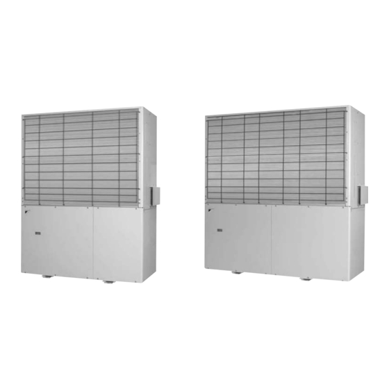
External Appearance SiAUY361411EA Outdoor Units GYEQ20AN GYEQ30AN BS Units BSGQ-P Air Treatment Equipment Heat Reclaim Ventilator (VAM series) VAM-GJ General Information... -
Page 17: Capacity Range
Maximum number of Capacity Model name Class connectable indoor index Combination (%) units 100% 130% GYEQ20AN 56.0 GYEQ30AN 85.0 Heat Recovery Operation Model BSGQ100PV1 BSGQ160PV1 BSGQ250PV1 Total capacity index of connectable 20 to 100 More than 100 but 160 or less... - Page 18 SiAUY361411EA Part 2 Device Overview 1. Model Naming ..................8 2. Unit Specifications...................9 3. External Diagrams.................10 4. Structural Diagrams ................12 5. System Diagrams..................14 5.1 Refrigerant System Diagrams ..............14 5.2 Cooling Water, Intake Air, Fuel and Engine Oil System Diagram ..23 6. Sensor Mounting Positions ..............25 6.1 Sensors Installed on the Engine.............25 6.2 Sensors Installed in the System .............26 7.
-
Page 19: Model Naming
SiAUY361411EA Model Naming 1. Model Naming GYEQ Indicates Major Design Category Capacity indication Conversion to kW 20: 56.0 kW 30: 85.0 kW Series, Type GYEQ: Gas Heat Pump Air Conditioner/Heat Recovery Device Overview... -
Page 20: Unit Specifications
Unit Specifications SiAUY361411EA 2. Unit Specifications Model Name GYEQ20AN GYEQ30AN Power Supply 1 phase, 200 V, 50 Hz 1 phase, 200 V, 50 Hz Type Natural gas Natural gas 1 Cooling Capacity 56.0 85.0 2 Heating Capacity 63.0 95.0 Casing Colour Ivory white (5Y7.5/1) -
Page 21: External Diagrams
SiAUY361411EA External Diagrams 3. External Diagrams GYEQ20AN Unit (mm) Device Overview... - Page 22 External Diagrams SiAUY361411EA GYEQ30AN Unit (mm) Device Overview...
-
Page 23: Structural Diagrams
SiAUY361411EA Structural Diagrams 4. Structural Diagrams GYEQ20AN Outdoor fan Mist separator Reservoir tank Sub circuit board Radiator F DCBL circuit board Motor valve Main circuit board Thermostat 60°C Power supply circuit board Breakers Exhaust silencer Transformer (starter) Cooling water pump... - Page 24 Structural Diagrams SiAUY361411EA GYEQ30AN Outdoor fan Mist separator Reservoir tank Sub circuit board Radiator B Radiator F DCBL circuit board Main circuit board Power supply circuit board Motor valve Thermostat 60°C Breakers Exhaust silencer Transformer (starter) Cooling water pump Engine Intake silencer Oil filter Oil subtank...
-
Page 25: System Diagrams
The indoor air is cooled through this evaporation heat deprivation process. • Finally, gasified refrigerant enters into the outdoor unit and returns via the solenoid valve to the compressor, completing one cooling cycle. GYEQ20AN Outdoor heat exchanger F Outdoor fan BS unit... - Page 26 System Diagrams SiAUY361411EA GYEQ30AN Outdoor heat exchanger F Outdoor fan BS unit Outdoor heat exchanger B (Discharge gas) Indoor unit (Intake gas) (Liquid) BS unit Receiver Indoor unit Oil separator cooler Compressor 1 : Solenoid valves : Check valve : Electronic expansion valve : Stop valve : Discharge temperature : Hi g h-si d e pressure swi t ch...
- Page 27 This completes one cooling/heating cycle. GYEQ20AN Outdoor heat exchanger F Outdoor fan...
- Page 28 System Diagrams SiAUY361411EA GYEQ30AN Outdoor heat exchanger F Outdoor fan BS unit Outdoor heat exchanger B (Discharge gas) Heating indoor unit (Intake gas) (Liquid) BS unit Receiver Cooling indoor unit Oil separator cooler Compressor 1 : Solenoid valves : Check valve : Electronic expansion valve : Stop valve : Discharge temperature...
- Page 29 This completes one cooling/heating cycle. ∗ The operations in parenthesis ( ) are not performed in the heating mode. GYEQ20AN Outdoor heat exchanger F Outdoor fan...
- Page 30 System Diagrams SiAUY361411EA GYEQ30AN Outdoor heat exchanger F Outdoor fan BS unit Outdoor heat exchanger B (Discharge gas) Indoor unit (Intake gas) (Liquid) BS unit Receiver Indoor unit Oil separator cooler Compressor 1 : Solenoid valves : Check valve : Electronic expansion valve : Stop valve : Discharge temperature : Hi g h-si d e pressure swi t ch...
- Page 31 SiAUY361411EA System Diagrams 5.1.4 Heating operation • High-temperature, high-pressure refrigerant gas compressed by the compressor is fed to the indoor heat exchanger, which in turn condenses the refrigerant gas and heats the indoor air by radiating the condensation heat; this is where the refrigerant changes from gas to liquid. •...
- Page 32 (hot water) of heat before returning to the compressor. The engine's waste heat is used as the heat source for heating operation. GYEQ20AN Outdoor heat exchanger F Outdoor fan...
- Page 33 SiAUY361411EA System Diagrams GYEQ30AN Outdoor heat exchanger F Outdoor fan BS unit Outdoor heat exchanger B (Discharge gas) Indoor unit (Intake gas) (Liquid) BS unit Receiver Indoor unit Oil separator cooler Compressor 1 : Solenoid valves : Check valve : Electronic expansion valve : Stop valve : Discharge temperature : Hi g h-si d e pressure swi t ch...
-
Page 34: Cooling Water, Intake Air, Fuel And Engine Oil System Diagram
System Diagrams SiAUY361411EA Cooling Water, Intake Air, Fuel and Engine Oil System Diagram Cooling water system diagrams Filament cap Outdoor fan M Radiator Refrigerant Filter Water Reservoir tank motor-operated valve Air discharge T Cooling water pump Thermostat (60ºC) Filter Engine Exhaust gas cooler G-6203J-A821-0-E Intake air system diagram... - Page 35 SiAUY361411EA System Diagrams Fuel system diagram Mixer Fuel hose Regulator Engine Enhanced fuel hose Valve Outdoor unit Double gas solenoid valve G-62034-A831-0-E Engine oil supply system diagram Engine Hose (equal pressure) Filter port Hose (LO) Subtank G-62034-A851-0-E Device Overview...
-
Page 36: Sensor Mounting Positions
Sensor Mounting Positions SiAUY361411EA 6. Sensor Mounting Positions Sensors Installed on the Engine Engine sensor mounting positions 3GPH88 (GYEQ20AN) Lubricating oil pressure switch Pulsar (for crank shaft rotation) Water temperature sensor Pulsar (for cam shaft rotation) 040432-00EN00 Engine sensor mounting positions 4GPH88 (GYEQ30AN) -
Page 37: Sensors Installed In The System
SiAUY361411EA Sensor Mounting Positions Sensors Installed in the System System sensor mounting positions GYEQ20AN High pressure Intake temperature sensor 4 1 sensor Outdoor heat exchanger F Outdoor fan BS unit Outdoor heat exchanger B (Discharge gas) Indoor unit (Intake gas) -
Page 38: Electrical Wiring Diagrams
Electrical Wiring Diagrams SiAUY361411EA 7. Electrical Wiring Diagrams GYEQ20AN / GYEQ30AN 046640-00EN00 Device Overview... -
Page 39: Installation Work Manual
SiAUY361411EA Installation Work Manual 8. Installation Work Manual Table of Contents 1 Safety Precautions ………………………………………… 1 2 Combinations with Indoor Units ………………………… 2 3 Selection of Installation Location ………………………… 3 4 Servicing Space Requirements for the Outdoor Units … 5 5 External Dimension Diagram/Servicing Space for External Filter …... - Page 40 1 Safety Precautions Safety Precautions WARNING DAIKIN Gas Heat Pump Air Conditioning units must be installed by piping work specialists, not by the user. Do not install the outdoor unit inside or partly inside a building. Confirm the product is suitable for the fuel gas type.
- Page 41 Select options suitable for the actual piping layout. Refer to the items in 6. Installing the Outdoor Unit before making the selection. Be sure to use refrigerant branch kits designed specifically for use with R410A. Consult your authorized Daikin dealer or distributor for any questions. – 2 – 0FGHP-EN0801 DGJ002...
- Page 42 Installation Work Manual SiAUY361411EA 3 Selection of Installation Location Selection of Installation Location Notes on Selecting the Installation Location Install the outdoor unit so that the exhaust gas does not enter building interiors WARNING through windows, intake and exhaust vents, piping leading to interiors, air vents, etc.
- Page 43 (2) Inspection and certification are performed only for optional items designed specifically for the Daikin GHP. Using items not specifically designed for use by the Daikin GHP may cause problems like abnormal vibration, etc. Install the outdoor unit in a location where there are no walls near the outdoor unit that could reflect or resonate with the operating sound.
- Page 44 When anchoring the outdoor unit with anchor bolts, there should be a sufficient space for handling and tightening the anchor bolts. GYEQ20AN [Multiple unit installation] [Single unit installation]...
- Page 45 SiAUY361411EA Installation Work Manual 5 External Dimension Diagram/Servicing Space for External Filter External Dimension Diagram/Servicing Space for External Filter WARNING Since the external filter may need to be replaced, refer to the figure below and make sure that there is sufficient servicing space for the replacement. [External filter for gas pipe] Filter for gas pipe (Top face)
- Page 46 Installation Work Manual SiAUY361411EA 6 Installation Foundation for Outdoor Units Installation Foundation for Outdoor Units Notes on Foundation and Installation Work Refer to the foundation drawings to execute foundation work for the outdoor unit; the foundation must be strong enough to support the weight of the outdoor unit and more than 100 mm higher than the floor surface to protect it from rainwater and dust.
- Page 47 SiAUY361411EA Installation Work Manual 6 Installation Foundation for Outdoor Units [Example of the direct-mount foundation] 1/50 downward pitch Drain ditch Plan Drain ditch When providing the When providing the foundation on the foundation on the ground: concrete floor: Floor 022596-00E00 Sectional view [Example of the elevated pad installation] 038229-00E00...
- Page 48 GYEQ20AN larger than the pipe diameter indicated in the table on the GYEQ30AN right hand to minimize loss of cooling performance due to the pipe length.
- Page 49 SiAUY361411EA Installation Work Manual 7 Installing the Outdoor Unit Piping between the refrigerant branch kit/BS units and refrigerant branch kit/BS units Choose one of the sizes Suction gas Discharge Fluid pipe from the table on the pipe gas pipe right hand depending on Less than 7.0 kW 7.0 kW or more but less t h e t o t a l c a p a c i t y o f...
- Page 50 (3 pipes) Outdoor unit REFNET Joint Total capacity REFNET Joint part REFNET Joint part capacity part number number number GYEQ20AN KHRP25A72T Less than 22.4kW KHRP25A22T KHRP26A22T GYEQ30AN KHRP25A73T 22.4 kW or more but less than 33.0 kW KHRP25A33T KHRP26A33T 22.4 kW or more but less than 71.0 kW KHRP25A72T + KHRP25M72TP 71.0 kW or more...
- Page 51 SiAUY361411EA Installation Work Manual 7 Installing the Outdoor Unit Refrigerant piping configuration, allowable piping lengths, and allowable height differences Make sure that the refrigerant piping lengths and height differences are within the following ranges. Piping side Cooling/heating mix operation units require BS units (units that allow switching between cooling and heating mode).
- Page 52 Installation Work Manual SiAUY361411EA 7 Installing the Outdoor Unit Refrigerant piping work and connection This section provides instructions to follow when performing refrigerant piping work. Only use copper pipes that have clean inner surfaces (e.g. free of moisture and dust). When you cut a refrigerant pipe, be sure to use a pipe cutter.
- Page 53 SiAUY361411EA Installation Work Manual 7 Installing the Outdoor Unit When braze-welding a copper pipe, be sure to blow with nitrogen (this is an absolute requirement for braze welding). Perform braze welding with nitrogen gas flowing through the copper pipe from one end to the other end. Cover the end of the copper pipe from which you blow in the nitrogen with tape to prevent air from getting sucked in.
- Page 54 Installation Work Manual SiAUY361411EA 7 Installing the Outdoor Unit Performing piping work using the external filter Install the external filter close to the outdoor unit. WARNING When the vibration proof stand is used, do not install the external filter close to the outdoor unit.
- Page 55 SiAUY361411EA Installation Work Manual 7 Installing the Outdoor Unit Performing piping work using the refrigerant branch kits (REFNET Joints and Headers) Be sure to use refrigerant branch kits designed specifically for use with R410A. Be sure to heat-insulate the branch kits in accordance with the supplied manual. (1) REFNET Joints (2) REFNET Headers (Gas side/fluid side branching pipes)
- Page 56 Installation Work Manual SiAUY361411EA 7 Installing the Outdoor Unit Connection to the outdoor unit There is a closing valve inside the outdoor unit. GYEQ20AN Valve stem [Discharge gas side] [Suction gas side] [Fluid side] The handle is fully closed when...
- Page 57 Introduction Daikin Gas Heat Pump Air Conditioning Units use R410A as their refrigerant. R410A is a safe, nontoxic, noncombustible refrigerant, but the room where the air conditioning unit is installed must be large enough to prevent the refrigerant gas concentration from reaching a dangerous level if a gas leak occurs.
- Page 58 Installation Work Manual SiAUY361411EA 0FGHP-EN0801 DGJ002 Device Overview...
- Page 59 SiAUY361411EA Installation Work Manual 7 Installing the Outdoor Unit Corresponding Flow Chart for Refrigerant Leakage Selection of Ventilation System Increase the residing space capacity, or review the outdoor unit capacity of the ventilation Selection: OK Total charged refrigerant amount in the system (kg) system or refrigerant piping length (No special handling Residing space capacity (m...
- Page 60 Installation Work Manual SiAUY361411EA 0FGHP-EN0801 DGJ002 Device Overview...
- Page 61 SiAUY361411EA Installation Work Manual 7 Installing the Outdoor Unit Heat retention work Be sure to heat-insulate both fluid and gas pipes. Use separate heat insulators to cover the fluid side and gas side pipes. Never use the same heat insulator to cover both fluid and gas pipes because doing so would result in performance loss and other problems.
- Page 62 Installation Work Manual SiAUY361411EA 7 Installing the Outdoor Unit Air tightness test and evacuation of refrigerant piping Air tightness test and evacuation [Fig. 1] Outdoor unit side Manifold gauge L H Use tools designed specifically for use with Charging hose B...
- Page 63 SiAUY361411EA Installation Work Manual 7 Installing the Outdoor Unit Normal vacuum drying (1) Vacuum Evacuate the piping from the fluid and gas (both intake gas and discharge gas for AFZP drying: models) sides of the outdoor unit's closing valve as well as from the servicing port. If a negative pressure of -0.101 MPa or less is attained during continuous evacuation for two hours or longer, then the vacuum drying process is complete.
- Page 64 Installation Work Manual SiAUY361411EA 7 Installing the Outdoor Unit Piping work for outdoor unit exhaust drain and condensed water drain pipes Precautions on drain piping work WARNING Separate pipes must be used for outdoor unit exhaust drain and for indoor unit drain. Sharing the same pipe between these two purposes could possibly cause intoxication due to exhaust gas backflow or a fault due to corrosion of a circuit board or some other part of the indoor unit.
- Page 65 (value shown in pipes [m] pipes [m] pipes [m] pipes [m] pipes [m] table below) Outdoor unit capacity GYEQ20AN GYEQ30AN Refrigerant correction amount 6.4 kg 13.9 kg CAUTION R410A must be charged as liquid refrigerant. CAUTION Recording the filled refrigerant amount When you refill the chlorofluorocarbon refrigerant, record the type and quantity of the chlorofluorocarbon on the sticker attached above the stop valve on the outdoor unit's terminal box cover.
- Page 66 Installation Work Manual SiAUY361411EA 7 Installing the Outdoor Unit Additional refrigerant charging Be sure to follow the below-mentioned procedure for additional refrigerant charging. CAUTION Charging with the wrong procedure will cause damage to the compressor. Turn on the power supply for the indoor, outdoor, and BS units, and confirm signal transmission for the indoor and outdoor units.
- Page 67 SiAUY361411EA Installation Work Manual 7 Installing the Outdoor Unit Checklist for the completion of work Confirm the following contents after the completion of work and adjust if required. Check Content The outdoor unit is installed outside the building. The installation location of the outdoor unit does not resemble an indoor location, e.g. a balcony surrounded by ventilation louvers.
-
Page 68: Wiring Manual
Wiring Manual SiAUY361411EA 9. Wiring Manual Table of Contents 1. Safety Precautions ………………………………………… 1 2. Wiring Connection and Capacity ………………………… 2 Selection of Wiring and Breakers …………………………………… 2 Wiring Connection …………………………………………………… 3 Sequential Startup …………………………………………………… 5 3. Setting and Rewiring the Outdoor Unit ………………… 6 Configuring the Outdoor Unit DIP Switches ………………………... - Page 69 SiAUY361411EA Wiring Manual 1. Safety Precautions Safety Precautions Precautions for Electrical Wiring Work Electrical work must be performed by qualified personnel with knowledge WARNING (certification) of electrical work in accordance with the regulations and standards (laws) related to electrical equipment and work and the installation (work) manual. Be sure to observe the capacity of the rated power supply, breaker, and switch, and cable specifications, and do the grounding wire (earthing) work.
- Page 70 Wire diameter Wire diameter Phase Voltage Frequency At starting Indoor unit ø1 220~240 0.75 0.75 GYEQ20AN ø1 0.75 0.75 Outdoor unit GYEQ30AN ø1 0.75 0.75 * 1. Black VV cable (two-or three-core) * 2. Sheathed vinyl cord or cable (two-core) Maximum length: 1000 m or shorter (total extended length: 2000 m) When using a shielded cable, be sure to ground only one end of the shielded cable.
- Page 71 SiAUY361411EA Wiring Manual 2. Wiring Connection and Capacity Wiring Connection About power supply wiring Use specified cables for wiring work. The cables should be perfectly connected to the appropriate connectors and fastened tightly so that the terminal connectors will not be exposed to external forces via the cables.
- Page 72 If there is an applicable legal regulation, however, that regulation takes precedence. [Offset distance] If the power supply cable belongs to an outdoor unit, indoor unit, or DAIKIN air conditioning system, the offset distance should be 50 mm or greater.
- Page 73 SiAUY361411EA Wiring Manual 2. Wiring Connection and Capacity Wiring connection locations Enlargement illustration of the unit interior Terminal block for transmission (communication) wiring Link cable Heating/ Link cable Link cable Link cable between Remote cooling between between between outdoor and communica- switching indoor and...
- Page 74 Wiring Manual SiAUY361411EA 3. Setting and Rewiring the Outdoor Unit . Setting and Rewiring the Outdoor Unit Configuring the Outdoor Unit DIP Switches CAUTION Before accessing the DIP switches, turn off the power and make sure that none of the LEDs on the circuit board are lit. Attempting to access the DIP switches with any LED lit could result in an electrical shock due to electricity remaining in the circuit.
- Page 75 SiAUY361411EA Wiring Manual 3. Setting and Rewiring the Outdoor Unit On-site Factory Name Parameter Description configuration Remarks default DSW2 Aggregate/ Enables aggregate cooling/heating control. Configure independent control when Enables independent cooling/heating control required. (standard setting). Parent/child control Enables aggregate cooling/heating control from Configure the parent.
- Page 76 Wiring Manual SiAUY361411EA 3. Setting and Rewiring the Outdoor Unit Main circuit board diagram EV1 CN13 EV4 CN16 EV5 CN17 EV2 CN14 EV6 CN18 EV3 CN15 CN20 LED5 DSW3 DSW4 DSW1 DSW2 LED1 LED2 LED3 Main CPU BACK NEXT ENTER Writing RUN 運転...
- Page 77 SiAUY361411EA Wiring Manual 3. Setting and Rewiring the Outdoor Unit Checklist for the Completion of Work Confirm the following contents after the completion of work and adjust if required. Check Item to confirm The electrical wiring uses a dedicated branch circuit that is not shared with other electric equipment. (The electrical wiring is an dedicated branch circuit.) An earth leakage circuit breaker, isolating switch (with fuse), or wiring circuit breaker with the appropriate capacity is used.
-
Page 78: Test Run Manual
Test Run Manual SiAUY361411EA 10.Test Run Manual Table of Contents 1 Safety Precautions ………………………………………… 1 2 How to Perform a Test Run ……………………………… 2 Checks Prior to the Test Run ……………………………………… 2 Checking the outdoor and indoor units …………………………… 2 Configuring the Outdoor Unit DIP Switches (Check) ……………... - Page 79 R410A refrigerant. The filled refrigerant type is recorded on the machine nameplate. DAIKIN is not responsible for any defects (including failures and malfunctions) and accidents caused by filling a refrigerant other than R410A. Recording the filled refrigerant amount sticker...
- Page 80 Check that the combination of the outdoor units and indoor units is correct. Possible combinations The following table shows the possible combinations with indoor units. Model GYEQ20AN GYEQ30AN Number of indoor units that can be connected 1-32 units 1-48 units...
- Page 81 SiAUY361411EA Test Run Manual 2 How to Perform a Test Run Configuring the Outdoor Unit DIP Switches (Check) Before accessing the DIP switches, make sure that all of the LEDs on the PCB are CAUTION off after the power source is turned off. Attempting to access the DIP switches with any LED lit can result in an electrical shock due to electricity remaining in the circuit.
- Page 82 Test Run Manual SiAUY361411EA 2 How to Perform a Test Run On-site Factory Name Parameter Description configuration Remarks default DSW2 Aggregate/ Enables aggregate cooling/heating control. Configure independent control when Enables independent cooling/heating control required. (standard setting). Parent/child control Enables aggregate cooling/heating control from Configure the parent.
- Page 83 SiAUY361411EA Test Run Manual 2 How to Perform a Test Run Main circuit board diagram EV1 CN13 EV4 CN16 EV5 CN17 EV2 CN14 EV6 CN18 EV3 CN15 CN20 LED5 DSW3 DSW4 DSW1 DSW2 LED1 LED2 LED3 Main CPU BACK NEXT ENTER Writing RUN 運転...
- Page 84 Install the accessory stoppers to the stop valves. (GYEQ20AN valves are intake gas side stop valves; GYEQ30AN only the stop valves on the discharge gas side) Leave for more than 24 hours after the power has been turned on.
- Page 85 SiAUY361411EA Test Run Manual 2 How to Perform a Test Run Refrigerant Misfilling Emergency Mode Perform the following procedure using the switches located next to the hour meter on the outdoor unit PCB. Switch operation may not be possible for approximately 10 minutes after the unit is turned on or the last operations.
- Page 86 Test Run Manual SiAUY361411EA 2 How to Perform a Test Run How to Use the PCB Checker CAUTION Wipe soil, oil and water from your hands before operating pushbuttons and switches on the PCB. Oil and water may cause electric shocks or the PCB to malfunction.
- Page 87 SiAUY361411EA Test Run Manual 2 How to Perform a Test Run How to Use the PCB Checker Button name Function You can use the PCB switch SW1 to switch the Selects a different channel (CH) checker function between the RUN and STOP modes. DOWN Selects a different channel (CH) NEXT...
- Page 88 Test Run Manual SiAUY361411EA 2 How to Perform a Test Run 1. Outdoor unit 1-1. Outdoor Unit Data Display (1) Enter RUN mode, select CH [1] at Level 1 and press NEXT . (2) Select CH [01] at Level 2 and press NEXT .
- Page 89 SiAUY361411EA Test Run Manual 2 How to Perform a Test Run 1-2. Actuator Operation Status Display (1) Enter RUN mode, select CH [1] at level 1 and press NEXT . (2) Select CH [02] or [03] at Level 2 and press NEXT .
- Page 90 Test Run Manual SiAUY361411EA 2 How to Perform a Test Run Content Content Clutch 1 Starter Clutch 2 Gas valve 1 Compressor heater 1 Gas valve 2 Compressor heater 2 Vacant Four-way valve 1 Starter transformer cut-off relay Oil separator heater Block heater Accumulator heater Exhaust drain heater...
- Page 91 SiAUY361411EA Test Run Manual 2 How to Perform a Test Run 2. Special operation (1) Enter RUN mode, select CH [2] at level 1 and press NEXT . (2) Select the CH of the desired mode (refer to the table below) at Level 2 and press NEXT .
- Page 92 Test Run Manual SiAUY361411EA 2 How to Perform a Test Run 3-2. Indoor Unit Thermostat ON Display (1) Enter RUN mode, select CH [3] at Level 1 and press NEXT . (2) Select CH [02] at Level 2 and press NEXT .
- Page 93 SiAUY361411EA Test Run Manual 2 How to Perform a Test Run 4. Item display 4-1. ON/OFF Unit (Memory Switch) (1) Enter RUN mode, select CH [4] at level 1 and press NEXT . (2) Select CH [01] at Level 2 and press NEXT .
- Page 94 Test Run Manual SiAUY361411EA 2 How to Perform a Test Run STOP Mode When switching the slide switch to STOP, the unit enters STOP mode. To leave the STOP mode, set SW1 to the RUN position so that the total operated hours are displayed. Be careful.
- Page 95 SiAUY361411EA Test Run Manual 2 How to Perform a Test Run 3. Configure items 3-1. ON/OFF Unit (Memory Switch) (1) Enter STOP mode, select CH [3] at Level 1 and press NEXT . (2) Select CH [01] at Level 2 and press NEXT .
- Page 96 Test Run Manual SiAUY361411EA 2 How to Perform a Test Run 4. Alarm/warning history (1) Enter STOP mode, select CH [4] at Level 1 and press NEXT . (2) Select the CH of the desired alarm/ warning (refer to the table below) at level 2 and press NEXT , the code and operation time at occurrence are displayed alternately.
- Page 97 SiAUY361411EA Test Run Manual 2 How to Perform a Test Run GYEQ Models Error Outdoor unit Inspection Unit Remote control display Lamp display display Blinking Indoor Unit - Remote Control Sensor Failure Blinking Blinking Blinking Engine Start is Faulty Blinking Blinking Blinking Engine Overspeed...
- Page 98 Test Run Manual SiAUY361411EA 2 How to Perform a Test Run GYEQ Models Error Outdoor unit Inspection Unit Remote control display Lamp display display Blinking Blinking Blinking Total Indoor Unit Capacity Too Large Inter-CPU Communication Failure / Software Mismatch / ROM Blinking Blinking Blinking...
- Page 99 SiAUY361411EA Test Run Manual 2 How to Perform a Test Run External Filter Clogging Judgment If "Cannot become cool/warm" trouble occurs during the test run, the external filter may be clogged. In this case, check the pressure difference from the servicing ports on the upstream and downstream of the external filter for the gas pipe.
- Page 100 SiAUY361411EA Part 3 Control and Functionality 1. Control Overview...................90 1.1 System Control Overview...............90 1.2 Startup Sequences.................93 1.3 Actuators ....................95 1.4 Setting Up and Rewiring the Outdoor Unit ..........96 2. Outdoor Unit Control ................98 3. Actuator Control ..................103 3.1 Electric Motor Operated Valve Control..........103 3.2 Pump Control ..................107 3.3 Fan Control...................107 3.4 Heater Control ..................107...
-
Page 101: Control And Functionality Part
SiAUY361411EA Control Overview 1. Control Overview System Control Overview Fig. 3.1/ System control flow chart Start Power ON Electronic expansion valve initialization Initial Settings Blowing or Blowing temperature control Temperature control Preventing restart (4 minutes) Indoor unit thermostat ON run signal Output one or more units? Protection device... - Page 102 Table 3.1/ Engine speed range (cooling) (min Outdoor units Model GYEQ20AN GYEQ30AN Maximum revolution 2200 2300 Full range Minimum revolution...
- Page 103 023271-00EN01 opening the high/low pressure bypasses (EV3) and solenoid valve (SV1). Table 3.2/ Engine speed range (heating) (min Outdoor units Model GYEQ20AN GYEQ30AN Maximum revolution 2800 2800 Full range Minimum revolution Maximum revolution 2800...
-
Page 104: Startup Sequences
Control Overview SiAUY361411EA Startup Sequences Fig. 3.4/ Outdoor unit startup sequence Go to (A). Go to (A). Control and Functionality... - Page 105 SiAUY361411EA Control Overview Normal startup The outdoor unit follows the time chart on the right when starting up heating and cooling operations. (Provided that the engine starts up (its speed exceeds 800 min ) the first time the starter is turned ON.) 6 sec.
-
Page 106: Actuators
Control Overview SiAUY361411EA Actuators Table 3.3/ Operation of each actuator Thermo- Cooling Concurrent System Name dehumidi- Heating cooling/ Blowing Defrosting Remarks Operation stop fication heating -OFF ∆ Gas 1 & 2 — — ∆ ∆ ∆ ∆ ∆ Fuel control valve —... -
Page 107: Setting Up And Rewiring The Outdoor Unit
SiAUY361411EA Control Overview Setting Up and Rewiring the Outdoor Unit Configuring the outdoor unit DIP switches Caution Before accessing the DIP switches, turn off the power and make sure that none of the LEDs on the circuit board are lit. Attempting to access the DIP switches with any LED lit could result in an electrical shock due to electricity remaining in the circuit. - Page 108 Control Overview SiAUY361411EA Fig. 3.5/ Example of connecting 20 indoor units using a refrigerant system address of "23" Outdoor unit Refrigerant piping system address is set at “23” DSW2 Unit number setting Unit number setting Total of 20 units RSW1 (units position) RSW1 (units position) DSW6 (tens position) DSW6 (tens position)
-
Page 109: Outdoor Unit Control
SiAUY361411EA Outdoor Unit Control 2. Outdoor Unit Control (Cooling/heating) "Inhibit" control function • If the outdoor air temperature drops to -10°C or lower during cooling, this function is activated to inhibit the cooling indoor unit only from operating. If the outdoor air temperature rises to 30°C or higher during heating, this function is activated to inhibit the heating indoor unit only from operating. - Page 110 Outdoor Unit Control SiAUY361411EA (Cooling/heating) "Stop Preparation Mode" control function Available with a cooling/heating outdoor unit, this function changes the refrigerant circuit while the outdoor unit is stopped so that the next startup can be smoothly performed. (Cooling/heating) "Refrigerant Recovery" control function Available with a cooling/heating outdoor unit, this function controls the recovery of refrigerant accumulated in the outdoor heat exchanger during concurrent cooling/heating operation in low outdoor air temperatures.
- Page 111 SiAUY361411EA Outdoor Unit Control (Heating) "Overload Capacity" control function [1.1 System Control Overview] See the Basic heating control section. (Heating) "Inhibit Operation under Overload" control function When the outdoor air temperature rises to 26°C or higher during heating and the "Overload Capacity"...
- Page 112 Outdoor Unit Control SiAUY361411EA (Cooling) (Heating) "Quiet Mode" control function When you need to operate the unit at a lower noise level than normal as is the case with cooling/heating during midnight hours, you can select the "quiet mode" by following the instructions given below.
- Page 113 SiAUY361411EA Outdoor Unit Control [Disabling the quiet mode via external contact input] To disable the quiet mode via external contact input, you can use the onboard checker of the main circuit board to set memory switch CH2- No.7 to the ON position. Memory switch CH2-No.7 External contact input Quiet mode Depends on the settings of memory switches...
-
Page 114: Actuator Control
Actuator Control SiAUY361411EA 3. Actuator Control Electric Motor Operated Valve Control EV1, SV8 [Cooling] • Adjusts the refrigerant amount in the condenser to the optimal level. • SV8 is closed (turned OFF). [Cooling main, heating main A] • Adjusts the refrigerant amount in the condenser to the optimal level. •... - Page 115 SiAUY361411EA Actuator Control [Cooling main, heating main A] • Keeps SH at the SC receiver outlet at a constant level. • When the low-side pressure is lower than the low-side pressure set-point, keeps the low-side pressure at a constant level. [Heating, heating main B] •...
- Page 116 Actuator Control SiAUY361411EA [Cooling main, heating main A, heating, heating main B] • When the engine is running at the minimum speed and yet the high-side pressure is higher than the high-side pressure set-point, hot gas is bypassed to lower the high-side pressure. Four-way valve [Cooling] •...
- Page 117 SiAUY361411EA Actuator Control [Cooling main, heating main A, heating, heating main B] • This valve is closed (turned OFF). • During oil return, recovers refrigerating machine oil by switching from the discharge gas pipe to the low pressure gas pipe. SV37 [Cooling, cooling main, heating main A, heating, heating main B] •...
-
Page 118: Pump Control
Actuator Control SiAUY361411EA Pump Control Cooling water pump [All modes] • The cooling water pump is always running while the unit is operating. Fan Control Fans [Cooling, cooling main, heating main A] • The fan speed is reduced when the high-side pressure is lower than the target high-side pressure. -
Page 119: Ignition Timing Control
SiAUY361411EA Actuator Control Ignition Timing Control [Speed sensor] The speed sensor system is designed to control the ignition timing using two sensors: cam pulse and crank pulse. [Ignition scheme] The system counts the speed pulses transmitted from the crank pulse sensor based on the speed pulses transmitted from the cam pulse sensor, and uses the "ignition timing map"... - Page 120 SiAUY361411EA Part 4 Troubleshooting 1. Troubleshooting the Outdoor Unit ............110 1.1 Error Codes ..................110 1.2 How to Use the Checker on PCB ............113 1.3 RUN Mode....................115 1.4 STOP Mode..................121 1.5 Main Operations in Servicing ...............125 2. Flow Charts for Troubleshooting ............128 2.1 Problems without Error Codes .............128 2.2 Problems with Error Codes ..............131 Device Overview...
-
Page 121: Troubleshooting The Outdoor Unit
SiAUY361411EA Troubleshooting the Outdoor Unit 1. Troubleshooting the Outdoor Unit Error Codes Your Yanmar Gas Heat Pump system constantly monitors its components for any errors. In the event that an error has occurred in a unit, the system automatically stops that unit. When an error occurs, the remote controller connected to the indoor unit notifies you of the error by displaying the corresponding error code while flashing the run lamp and inspection indicator. - Page 122 Troubleshooting the Outdoor Unit SiAUY361411EA Indoor Unit system Code Code displayed displayed Error Inspection indicator Unit No. lamp outdoor remote unit controller Discharge Temperature Sensor Disconnected / Blinking Blinking Blinking Shorted Blinking Blinking Blinking Abnormal Engine Room Temperature Blinking Blinking Blinking Short of Refrigerant Blinking Blinking Blinking Compressor Oil Detected Too Low...
- Page 123 SiAUY361411EA Troubleshooting the Outdoor Unit Indoor Unit system Code Code displayed displayed Error Inspection indicator Unit No. lamp outdoor remote unit controller — Blinking Blinking Blinking Failure of Another Unit in the Same System Blinking Blinking Blinking Indoor Unit and Remote Control Mismatch —...
-
Page 124: How To Use The Checker On Pcb
Troubleshooting the Outdoor Unit SiAUY361411EA How to Use the Checker on PCB Fig. 4.1/ Checker on PCB BACK NEXT ENTER DATA DOWN STOP Checker Wiring 022638-00E change Caution • Wipe soil, oil and water from your hands before operating pushbuttons and switches on the PCB. - Page 125 SiAUY361411EA Troubleshooting the Outdoor Unit 1.2.2 Hour Meter / Error Code Display The hour meter (7-segment meter) on the PCB displays the total operated hours time during normal operation. When an error or fault occurs, the total operated hours and error code are displayed alternately and repeatedly at one second intervals.
-
Page 126: Run Mode
Troubleshooting the Outdoor Unit SiAUY361411EA RUN Mode ENTER NEXT NEXT • When you press (hereafter only is indicated for simplicity) button while SW1 is in the RUN position and the total operated hours are displayed, RUN mode is activated. ("1.___________" appears on the LCD.) BACK •... - Page 127 SiAUY361411EA Troubleshooting the Outdoor Unit 1.3.1 Outdoor Units Outdoor unit data display NEXT (1) Enter RUN mode, select CH [1] in Level 1 and press . (2) Select CH [01] in Level 2 and press . (3) When the CH (Table 4.4) of the desired data item is selected in NEXT Level 3, the data is displayed.
- Page 128 Troubleshooting the Outdoor Unit SiAUY361411EA Actuator operation status display NEXT (1) Enter RUN mode, select CH [1] in Level 1 and press . (2) Select CH [02] or [03] in Level 2 and press . (3) When the CH (Table 4.5, Table 4.6) of the desired actuator is NEXT selected in Level 3, the operation status is displayed.
- Page 129 SiAUY361411EA Troubleshooting the Outdoor Unit Table 4.6/ (List of actuator operation status 2) Select CH [03] in Level 2 CH No. Content CH No. Content Clutch 1 Starter Clutch 2 Gas valve 1 Compressor heater 1 Gas valve 2 Compressor heater 2 (Reserved for future use) Four-way valve 1 Starter transformer cut-off relay...
- Page 130 Troubleshooting the Outdoor Unit SiAUY361411EA 1.3.2 Special Operation NEXT (1) Enter RUN mode, select CH [2] in Level 1 and press . (2) Select the CH of the desired mode (Table 4.7) in Level 2 and press . (3) Change the setting (such as ON/ NEXT OFF) using , and then press...
- Page 131 SiAUY361411EA Troubleshooting the Outdoor Unit 1.3.3 Item Display ON/OFF unit (memory switch) NEXT (1) Enter RUN mode, select CH [4] in Level 1 and press . (2) Select CH [01] in Level 2 and press . (3) Select the CH (Table 4.8) of the desired item in Level 3 and press NEXT .
-
Page 132: Stop Mode
Troubleshooting the Outdoor Unit SiAUY361411EA STOP Mode • When the slide switch is switched to STOP, the unit enters STOP mode. • To exit from STOP mode, set SW1 to the RUN position so that the total operated hours are displayed. - Page 133 SiAUY361411EA Troubleshooting the Outdoor Unit 1.4.2 Actuator Check NEXT (1) Enter STOP mode, select CH [2] in Level 1 and press . (2) Select the CH (Table 4.11) of the desired actuator in Level 2 and press . (3) Change the setting (such as NEXT ON/OFF) using , and then press...
- Page 134 Troubleshooting the Outdoor Unit SiAUY361411EA 1.4.3 Configure Items ON/OFF unit (memory switch) NEXT (1) Enter STOP mode, select CH [3] in Level 1 and press . (2) Select CH [01] in Level NEXT 2 and press . (3) Select the CH (Table 4.12) of the item you want to change in Level 3 and press .
- Page 135 SiAUY361411EA Troubleshooting the Outdoor Unit 1.4.4 Alarm/Warning History NEXT (1) Enter STOP mode, select CH [4] in Level 1 and press . (2) Select the CH of the desired alarm/warning (Table 4.13) in Level 2 and press . The code and operation NEXT time at occurrence are displayed alternately.
-
Page 136: Main Operations In Servicing
Troubleshooting the Outdoor Unit SiAUY361411EA Main Operations in Servicing Caution • If you are instructed to reset the outdoor unit's power supply, after turning off the power, make sure that none of the LEDs on the circuit board are lit before turning the power back on. •... - Page 137 SiAUY361411EA Troubleshooting the Outdoor Unit Pump down operation procedure 1. On the outdoor unit, close the liquid side stop valve. 2. With the onboard checker set to the RUN mode, select "2. Special operation" to start the pump down operation. For information on how to perform the special operation, see page 114 [How to Use the Checker on PCB] and page 115 [RUN Mode].
- Page 138 Troubleshooting the Outdoor Unit SiAUY361411EA [After replacing the mixer, regulator, or engine] If you have replaced the mixer, regulator, or engine, clear the initial GVM correction amount. • These clearing operations must be performed after replacing the part. For information on the operating methods, see page 114 [How to Use the Checker on PCB] and page 121 [STOP Mode].
-
Page 139: Flow Charts For Troubleshooting
SiAUY361411EA Flow Charts for Troubleshooting 2. Flow Charts for Troubleshooting Problems without Error Codes Unit Fails To Start Flow chart Unit Fails To Start Check Power Supply Is Unit Powered ON? Connections For Outdoor And Indoor Units. Is operation mode RUN on the Main Circuit Change the SW1 to RUN. - Page 140 Check Pipes. operating normally? Is the external filter free Check the external filter. of defects? Please contact your Daikin (Yanmar) representative if you can not find the cause even after you have checked all the items down to the bottom of the flowchart.
- Page 141 Is the external filter free Check the external filter. of defects? Please contact your Daikin (Yanmar) representative if you can not find the cause even after you have checked all the items down to the bottom of the flowchart.
-
Page 142: Problems With Error Codes
Flow Charts for Troubleshooting SiAUY361411EA Problems with Error Codes Error Engine Fails To Start Up code Description Sub-code 0: The engine speed does not exceed 800 min during the startup sequence. of the failure Possible Fuel supply failure; starter system failure; ignition system failure; intake/exhaust system failure; causes incorrect compression;... - Page 143 SiAUY361411EA Flow Charts for Troubleshooting Error Engine Overspeed code Sub-code 0: While the unit is running, the engine speed exceeds the maximum speed specific to the model Description of the failure plus the regulated speed specific to the model. Rib belt broken; mixer malfunctioning; clutch malfunctioning; crank pulse sensor gap incorrect; Possible causes blow-by system failure;...
- Page 144 Flow Charts for Troubleshooting SiAUY361411EA Error Engine Stall code Description Sub-code 0: While the unit is running, the engine speed falls to 400 min or lower. of the failure Possible Fuel supply failure; ignition system failure; intake/exhaust system failure; incorrect compression; causes incorrect valve clearance;...
- Page 145 SiAUY361411EA Flow Charts for Troubleshooting Error Oil Pressure Too Low code Sub-code 0: The oil pressure switch is ON in 15 seconds after engine startup. Description of the failure Oil pressure switch contact failure; pressure regulator valve failure; oil filter clogged; oil level too low; Possible causes engine oil abnormally consumed;...
- Page 146 Flow Charts for Troubleshooting SiAUY361411EA Error Abnormal Cooling Water Temperature code Sub-code 0: While the unit is running, the cooling water temperature rises beyond 105°C. Description Sub-code 1: The cooling water temperature fails to reach 40°C within 20 minutes after the engine has started of the failure Cooling water pump failure;...
- Page 147 SiAUY361411EA Flow Charts for Troubleshooting Error Abnormal Discharge Temperature code Sub-code 0: While the unit is running, discharge temperature 1 rises beyond 120°C. Sub-code 1: While the unit is running, discharge temperature 2 rises beyond 120°C. Sub-code 2: While the unit is running, discharge temperature 1 remains equal to or higher than the discharge Description predicted temperature for 10 minutes.
- Page 148 Flow Charts for Troubleshooting SiAUY361411EA Error Abnormal High-Side Pressure code Sub-code 0: While the unit is running, high-side pressure 1 rises to 3.85 MPa or higher. Sub-code 1: While the unit is running, high pressure SW1 or high pressure SW2 turns OFF, clutch 1 turns ON, and clutch 2 turns ON.
- Page 149 SiAUY361411EA Flow Charts for Troubleshooting Error Abnormal Low-Side Pressure code Description Sub-code 0: While the unit is running, the low-side pressure drops to 0.05 MPa or lower. of the failure Or the low-side pressure remains equal to or lower than 0.12 MPa for 20 seconds. Sensor failure;...
- Page 150 Flow Charts for Troubleshooting SiAUY361411EA Error Abnormal EEPROM code Description Sub-code 0: EEPROM's internal data area is unreadable. of the failure EEPROM failure; main circuit board failure Possible causes of the failure Flow chart Is EEPROM Installed Correctly? Install EEPROM Correctly. Change Main Circuit Board.
- Page 151 SiAUY361411EA Flow Charts for Troubleshooting Error Starter System Failure code Description Sub-code 0: The engine speed signal is not output within 3 seconds after the starter has been turned ON. of the failure Starter system failure; main circuit board failure; cam crank pulse sensor failure; oil level high; Possible causes insufficient equalization of refrigerant;...
- Page 152 Flow Charts for Troubleshooting SiAUY361411EA Error Outdoor Fan Failure code Description Sub-code 0: All fans fail to run within 60 seconds after they receive a Run command. of the failure Fan failure; harness failure; DCBL circuit board failure; main circuit board failure Possible causes of the failure...
- Page 153 SiAUY361411EA Flow Charts for Troubleshooting Error Oil Pressure Switch System Failure code Description Sub-code 0: The oil pressure switch fails to turn from ON to OFF within 15 seconds after engine startup. of the failure Oil pressure switch failure; harness failure; main circuit board failure; engine lubricating oil pump failure Possible causes of the failure...
- Page 154 Flow Charts for Troubleshooting SiAUY361411EA Discharge Temperature Sensor Disconnected/ Error Shorted code Sub-code 0: While the unit is running, the outdoor air temperature is 10°C or higher but discharge temperature 1 fails to rise above 0°C (which means that discharge temperature sensor 1 is disconnected).
- Page 155 Is There Any Trace Of Engine Room Make sure the burnout position and please contact Having Reached Abnormally High Temperature your Daikin representative. Due to Combustion or Other Reason? Are Intake Air And Check Intake Air And Oil Temperature Sensors Oil Temperature Sensors.
- Page 156 Flow Charts for Troubleshooting SiAUY361411EA Error Compressor Oil Detected Too Low code Sub-code 0: An empty oil separator has been detected. Sub-code 2: While oil separator heating control is being performed, SH01 or SH02 whichever is lower stays equal to or lower than 5°C for 40 minutes. Description of the failure Sub-code 3: SH01 or SH02 whichever is lower stays equal to or lower than 10°C for 5 minutes, or stays equal...
- Page 157 SiAUY361411EA Flow Charts for Troubleshooting Flow chart When Sub-code is 2 3 Is There 6 Hours or More Maintain Power-Up Time Power-Up Time Prior to Running? Is Correct Procedure Start Improper Additional Used for Additional Refrigerant Charging Recovery Mode Refrigerant Charging? IS Power-ON Start / Disable Power-ON/ Power-OFF Stop Enabled?
- Page 158 Flow Charts for Troubleshooting SiAUY361411EA Error Abnormal High-Side Differential Pressure code Sub-code 0: While the unit is running, the currently reported high-side pressure is equal to or higher than 3.1 MPa and the previously reported high-side pressure is equal to or lower than 2.9 MPa. Description of the failure Sub-code 1: While the unit is running, the currently reported high-side pressure is equal to or higher than 2.6...
- Page 159 SiAUY361411EA Flow Charts for Troubleshooting Error Misfire Detected code Sub-code 0: During 60 cycles, 48 or more misfires are reported 30 times consecutively. Sub-code 1: The voltage equivalent to the primary coil current of cylinder #1 remains 0 for 1 second. Description Sub-code 2: The voltage equivalent to the primary coil current of cylinder #2 remains 0 for 1 second.
- Page 160 Flow Charts for Troubleshooting SiAUY361411EA Error Clutch Failure code Sub-code 0: While the unit is running, PH-PL is higher than 500 kPa and the deviation from the target engine speed remains equal to or higher than 500 min for 0.5 seconds. This condition is not judged until 20 seconds elapse after the clutch is operated.
- Page 161 SiAUY361411EA Flow Charts for Troubleshooting Error Indoor Unit Electronic Expansion Valve Failure code Sub-code 0: During cooling operation, the following conditions continue for 20 minutes: 1) SHS1 is equal to or Description lower than 2°C; 2) SHS2 is equal to or lower than 2°C; 3) the high-side pressure minus low-side of the failure pressure is equal to or higher than 1000 kPa.
- Page 162 Flow Charts for Troubleshooting SiAUY361411EA Error Air-Fuel Ratio Controller Failure code Sub-code 0: While the unit is running, the air-fuel ratio controller does not function properly. Description Sub-code 1: While the unit is running, the following conditions continue for 3 minutes: 1) the throttle valve of the failure opening degree is equal to or lower than 500 pulses;...
- Page 163 SiAUY361411EA Flow Charts for Troubleshooting Outdoor Air Temperature Sensor Disconnected/ Error Shorted code Sub-code 0: While the unit is running, the outdoor air temperature is reported as 200°C (which means that the outdoor air temperature sensor is disconnected). Description of the failure Sub-code 1: While the unit is running, the outdoor air temperature is reported as 201°C (which means that the outdoor air temperature sensor is shorted).
- Page 164 Flow Charts for Troubleshooting SiAUY361411EA Error Outdoor Unit Electronic Expansion Valve Failure code Sub-code 0: During heating operation, the following conditions continue for 20 minutes: 1) SHS2 is equal to or lower than 2°C; 2) SHS2 is equal to or lower than 2°C; 3) SHS3 is higher than 3.5°C; 4) SHS4 is higher than 3.5°C;...
- Page 165 SiAUY361411EA Flow Charts for Troubleshooting Error Oil Return Solenoid Valve Failure code Sub-code 0: While the unit is running, the SV3 closing failure flag is ON. Sub-code 1: While the unit is running, the SV3 opening failure flag is ON. Description Sub-code 2: While the unit is running, the SV4 closing failure flag is ON.
- Page 166 Flow Charts for Troubleshooting SiAUY361411EA Error High-Side Pressure Sensor System Failure code Sub-code 0: While the unit is running, high-side pressure 1 is reported as 5000 kPa (which means that high- side pressure sensor 1 is shorted). Sub-code 1: While the unit is running, high-side pressure 1 is reported as 5100 kPa (which means that high- side pressure sensor 1 is disconnected).
- Page 167 SiAUY361411EA Flow Charts for Troubleshooting Error Exhaust Temperature Sensor Disconnected code Sub-code 0: While the unit is running, the following conditions continue for 5 minutes: 1) The engine speed is Description equal to or higher than 1400 min ; 2) the engine load is equal to or higher than 0.3 MPa; 3) the of the failure exhaust temperature is equal to or lower than 160°C.
- Page 168 Flow Charts for Troubleshooting SiAUY361411EA Error Compressor Automatic Emergency Run code Sub-code 0: Changes from E0-0 (engine fails to start) or E2-0 (engine stall) to compressor automatic emergency run (compressor 1 failure). Sub-code 1: Changes from E0-0 (engine fails to start) or E2-0 (engine stall) to compressor automatic emergency run (compressor 2 failure).
- Page 169 SiAUY361411EA Flow Charts for Troubleshooting Error Pressure Sensor Failure code Sub-code 0: While the unit is stopped, the following conditions continue for 20 seconds: 1) High-side pressure 1 minus the low-side pressure is equal to or higher than 170 kPa; 2) high-side pressure 1 is equal to or lower than 3300 kPa;...
- Page 170 Flow Charts for Troubleshooting SiAUY361411EA Error Oil Temperature Sensor Disconnected/Shorted code Sub-code 0: After 20 minutes have elapsed since the start of operation, clutch 1 is ON and oil temperature 1 remains equal to or lower than -30°C for 1 minute. Sub-code 1: While the unit is running, oil temperature 1 is reported as 201.0°C (which means that oil temperature sensor 1 is shorted).
- Page 171 SiAUY361411EA Flow Charts for Troubleshooting Error Receiver Temperature Sensor System Failure code Sub-code 0: While the unit is running, receiver temperature 31 is reported as 200°C (which means that receiver temperature sensor 31 is disconnected). Description of the failure Sub-code 1: While the unit is running, receiver temperature 31 is reported as 201°C (which means that receiver temperature sensor 31 is shorted).
- Page 172 Flow Charts for Troubleshooting SiAUY361411EA Error Abnormal Exhaust Temperature code Description Sub-code 0: While the unit is running, the exhaust temperature rises to or above 650°C. of the failure Misfire (ignition system failure); mixer failure; fuel gas type setting incorrect; engine oil up; engine oil down; Possible causes exhaust temperature sensor failure;...
- Page 173 SiAUY361411EA Flow Charts for Troubleshooting Periodic Inspection Reminder (Note: This is not Error an error message) code Sub-code 0: Engine oil replacement judgment Description of the failure Sub-code 1: Engine oil refill judgment Maintenance time reached; operating hour meter not reset after previous maintenance; Possible causes fuel gas type setting incorrect...
- Page 174 Flow Charts for Troubleshooting SiAUY361411EA Error BS Unit Circuit Switch Failure code Sub-code 0: With PH higher than 2.0 MPa and PH-PL higher than 1.2 MPa, condition (1) or (2) below continues for 6 minutes: Description (1) With the indoor unit heating thermostat ON, intake temperature gas pipe temperature liquid pipe of the failure...
- Page 175 SiAUY361411EA Flow Charts for Troubleshooting Error Too Many Indoor Units Connected code Description Sub-code 0: The number of connected indoor units is beyond the upper limit specific to the outdoor unit of the failure model. Upper limit of connected indoor units exceeded; CPU mismatch; communication line connection failure; Possible causes communication line incorrectly installed...
- Page 176 Flow Charts for Troubleshooting SiAUY361411EA Inter-CPU Communication Failure/ Error Software Mismatch/Abnormal ROM code Sub-code 0: Unable to communicate between I/O CPUs for 20 seconds. Description Sub-code 2: Unable to communicate between ignition CPUs for 20 seconds. of the failure Sub-code 3: Abnormal I/O CPU ROM Sub-code 5: Abnormal ignition CPU ROM CPU program write error;...
- Page 177 SiAUY361411EA Flow Charts for Troubleshooting Error Inter-Unit Communication Failure code Sub-code 0: Unable to communicate between DCBL circuit boards for 20 seconds or longer Description Sub-code 1: Unable to communicate between sub circuit boards for 20 seconds or longer of the failure Sub-code 2: Abnormal sub circuit board ROM Power supply failure;...
- Page 178 Flow Charts for Troubleshooting SiAUY361411EA Error Outdoor/Indoor Unit Transmission Failure code Sub-code 0: The outdoor and indoor units are unable to communicate with each other within 50 seconds after Description power-ON or unable to communicate with each other within 3 minutes after they are connected of the failure over the communication link (which means that all the indoor units have a transmission failure).
- Page 179 SiAUY361411EA Flow Charts for Troubleshooting Error Indoor Unit and Remote Control Mismatch code Sub-code 2: The number of connected remote control units does not match the number of supported remote Description control units specific to the model. of the failure Sub-code 5: Unable to receive signals from the ignition CPU when the power is turned ON.
- Page 180 SiAUY361411EA Part 5 Parts Inspection 1. Inspecting the Outdoor Unit ..............170 1.1 Safety Precautions for Inspecting or Servicing the Outdoor Unit ..170 1.2 Inspecting the Starter System ..............171 1.3 Inspecting the Fuel Control System .............173 1.4 Inspecting the Mixer System ..............174 1.5 Inspecting the Ignition System .............176 1.6 Inspecting the Regulator ..............179 1.7 Inspecting the Valve Clearance............179...
-
Page 181: Inspecting The Outdoor Unit
SiAUY361411EA Inspecting the Outdoor Unit 1. Inspecting the Outdoor Unit Safety Precautions for Inspecting or Servicing the Outdoor Unit Table 5.1/ Safety precautions for inspecting or servicing the outdoor unit The outdoor unit must be stopped before and during inspection. Everyone should be warned that the outdoor unit is under inspection and directed never to operate the outdoor unit via a remote control unit or by any other means. -
Page 182: Inspecting The Starter System
40 mΩ ∗ At 20°C (reference value) Inspecting the reactor Inspect the reactor by measuring the resistance between its terminals. ∗ Measuring points Model Measured value (Ω) GYEQ20AN 0.17 ∗ Between terminals GYEQ30AN 0.06 ∗ At 20°C (reference value) Parts Inspection... - Page 183 SiAUY361411EA Inspecting the Outdoor Unit Inspecting the self-starter motor Inspect the self-starter motor by measuring the resistance between its terminals and the ground. Measuring points Measured value 0.2 Ω Between S terminal and ground 0.2 Ω Between M terminal and ground M terminal S terminal 025942-00E...
-
Page 184: Inspecting The Fuel Control System
Inspecting the Outdoor Unit SiAUY361411EA Inspecting the Fuel Control System Output voltage During system While system running Parts to inspect Measuring points stop (with actuator check ON) Gas solenoid Between main circuit board's CH03 valve 1 CN9-1 and -4 12 V DC Gas solenoid Between main circuit board's CH04... -
Page 185: Inspecting The Mixer System
SiAUY361411EA Inspecting the Outdoor Unit Inspecting the Mixer System Output voltage Parts to inspect Measuring points Power supply ON Between main circuit board's CN8-1 and CN1-3 12 V DC Throttle valve Between main circuit board's CN8-3 and CN1-3 12 V DC Between main circuit board's CN8-2 and CN1-3 12 V DC Fuel control valve... - Page 186 Inspecting the Outdoor Unit SiAUY361411EA Adjusting the mixer At a time other than a test run, inspect the mixer to check if the O concentration is within the standard adjustment range. If beyond the range, adjust the O concentration using the needle regulator valve (MAS).
-
Page 187: Inspecting The Ignition System
SiAUY361411EA Inspecting the Outdoor Unit Inspecting the Ignition System Output voltage During While system is running Parts to inspect Measuring points system (with actuator check ∗ stop CH1 ON) Between starter transformer's Primary side 200 V AC input terminals Between main circuit board's 14 V DC Ignition CN20-5 and -6... - Page 188 Inspecting the Outdoor Unit SiAUY361411EA Inspecting the ignition coil Inspect the ignition coil by measuring the resistance between its primary side terminals. Measuring points Measured value 0.7 Ω Between terminals Secondary power Part No., NGK item No. output V2 out Primary power output (V-) Primary power output (V+)
- Page 189 SiAUY361411EA Inspecting the Outdoor Unit Inspecting the spark plugs Check the electrode of each ignition plug for any damage, stains, and wear. If the electrode is stained, clean the electrode and check and adjust the spark gap. If the electrode is damaged or worn, replace it with new one. Measured value Measuring points 3GPH88...
-
Page 190: Inspecting The Regulator
Inspecting the Outdoor Unit SiAUY361411EA Inspecting the Regulator While blowing in air through the gas inlet, check the hole open to the atmosphere for any leaks. (Submerge the regulator in water and check for any leaks based on whether air bubbles are seen.) Hole open to the atmosphere... -
Page 191: Inspecting The Compression Pressure
SiAUY361411EA Inspecting the Outdoor Unit Inspecting the Compression Pressure 1. Disconnect all cylinders' ignition coil primary side wiring terminals. 2. Remove the spark plug from the cylinder being tested, and then attach a compression gauge. 3. Measure the pressure while the system is running in manual/auto operation mode. (The throttle opening degree should be the startup opening degree [120 pulses].) ∗... -
Page 192: Inspecting The Air Cleaner
Inspecting the Outdoor Unit SiAUY361411EA 1.10 Inspecting the Air Cleaner Remove the air cleaner cover, and pull out the element. Check the cleaner interior and the element for any dirt or dust. Cover Cleaner body Element 023467-00E 1.11 Inspecting the Breather Hose Remove the breather hose from the engine bonnet, and check if there is any sludge remaining in the hose. -
Page 193: Inspecting The Engine Oil Level
If the lubricating oil consumption is abnormally high, chances are that there is a faulty valve train part (such as a stem seal) or a faulty piston ring. After repair, refill lubricating oil to the standard level. GYEQ20AN GYEQ30AN Factory oil level ("A" in the figure below) Factory oil level ("B"... -
Page 194: Inspecting Refrigerating Machine Oil And Refrigerant
Inspecting the Outdoor Unit SiAUY361411EA 1.13 Inspecting Refrigerating Machine Oil and Refrigerant Inspecting the oil separator 1. Make preparations so that you can measure the gas pressures at the high-side pressure servicing port and stop valve using a manifold gauge. 2. -
Page 195: Inspecting The Cooling Water Filter
SiAUY361411EA Inspecting the Outdoor Unit 1.14 Inspecting the Cooling Water Filter Pinch the rubber hose connected to the cooling water filter, and remove the filter. Check the mesh in the filter for dirt. If there is any dirt, remove it immediately. 025950-00X 1.15 Checking the Cooling Water System for Water Leaks Inspecting the radiator cap... -
Page 196: Inspecting The Cooling Water Level
Inspecting the Outdoor Unit SiAUY361411EA 1.16 Inspecting the Cooling Water Level Check the water level in the reservoir tank. If the water level is below the LOW tick mark, chances are that the cooling water is leaking or was not refilled during the previous periodic inspection. Check for any leaks, and refill cooling water. -
Page 197: Inspecting The Thermostat
SiAUY361411EA Inspecting the Outdoor Unit Inspecting the water motor-operated valve Inspect the water motor-operated valve by measuring the resistance between its connectors. Measuring points Measured value Between terminals #2 (red) and #4 (pink) 70Ω Between terminals #1 (amber) and #2 (red) 70Ω... -
Page 198: Inspecting The Cooling Water Concentration
Inspecting the Outdoor Unit SiAUY361411EA 1.19 Inspecting the Cooling Water Concentration Inspect the cooling water concentration using a coolant tester. The concentration should be 50%. Adjusting screw Focusing ring Silver cylinder Lens Cover 1.40 1.35 1.30 1.25 1.20 1.15 1.10 Prism Basal line 020937-00E... -
Page 199: Inspecting The Exhaust Temperature Sensor
SiAUY361411EA Inspecting the Outdoor Unit 1.22 Inspecting the Exhaust Temperature Sensor Test the continuity between connector terminals. If the reported temperature is normal, you only have to check whether or not continuity exists. If no continuity is detected but your inspection finds no problems with the exhaust temperature sensor itself, chances are that there is a contact failure. -
Page 200: Inspecting The Compressor
Inspecting the Outdoor Unit SiAUY361411EA 1.23 Inspecting the Compressor Checking for gas leaks 1. Using a leak tester, check if refrigerant is leaking from the drain tube. 2. Visually check if a significant amount of refrigerating machine oil is leaking from the drain tube. -
Page 201: Inspecting The Compressor Clutch
12 V DC Inspecting the compressor clutch Inspect the compressor clutch by measuring the resistance between its connectors and the ground. Type Measuring points Measured value SD type (for GYEQ20AN) Between 3.2 Ω harnesses and ground 025954-00X MHI type (for GYEQ20AN/GYEQ30AN) Between 6.3 Ω... -
Page 202: Inspecting The Solenoid Valves
Inspecting the Outdoor Unit SiAUY361411EA 1.25 Inspecting the Solenoid Valves 1. While the unit is running, turn ON each solenoid valve either directly or via the actuator check function, and check the output voltage and operating noise at the output connector (shown in the figure above) of the circuit board. -
Page 203: Inspecting The Outdoor Fan Motor
SiAUY361411EA Inspecting the Outdoor Unit 1.26 Inspecting the Outdoor Fan Motor Caution When you inspect the outdoor fan motor with the outdoor unit powered ON, take extreme care not to directly touch the circuit board (except the switches) or you may get an electrical shock. Even with the power OFF, there is a risk of an electric shock when any circuit board has an LED still lit. -
Page 204: Inspecting The Refrigerant Amount
Inspecting the Outdoor Unit SiAUY361411EA 1.27 Inspecting the Refrigerant Amount Checking whether refrigerant is undercharged or overcharged Determine whether refrigerant is undercharged or overcharged based on the criteria given in the following table: Measuring points Run mode Measured value In a steady state during operation, the number of pulses from EV4 is higher than 70, and the temperature Cooling measured on the copper pipe surface, [T1]-[T2], is lower... -
Page 205: Inspecting The Check Valve
SiAUY361411EA Inspecting the Outdoor Unit 040430-00X00 ∗ This model is slightly different from other models, but there is no significant difference regarding the measuring points. 1.28 Inspecting the Check Valve 1. While the unit is running, check if a temperature difference exists between points A and B in the pipe when the pipe internal pressure is lower at point A than at point B. -
Page 206: Inspecting The Electronic Expansion Valve
Inspecting the Outdoor Unit SiAUY361411EA 1.29 Inspecting the Electronic Expansion Valve Inspect the electronic expansion valve by measuring the resistance of its coil. Measuring points Measured value 46 Ω Between terminals #1 (red) and #4 (white) 46 Ω Between terminals #1 (red) and #6 (amber) 46 Ω... -
Page 207: Checking Stop Valve Operation
Inspecting the Outdoor Unit 1.30 Checking Stop Valve Operation Check if the stop valve turns in the correct direction when opened/closed. There is a stop valve inside the outdoor unit. GYEQ20AN Valve stem [Discharge gas side] [Suction gas side] [Fluid side]... -
Page 208: Inspecting The Four-Way Valve
Inspecting the Outdoor Unit SiAUY361411EA 1.31 Inspecting the Four-way Valve Output voltage With actuator check Parts to inspect Measuring points Between power supply circuit CH12 Four-way valve (normal heating) board's CN112-1 and -3 200 V AC 1. Using a tester, check if the output voltage requirements specified above are met. 2. -
Page 209: Inspecting The Refrigerant System Sensors
SiAUY361411EA Inspecting the Outdoor Unit 1.33 Inspecting the Refrigerant System Sensors Inspecting the high pressure switch Check the continuity between terminals. There should be continuity while stopped. Working pressure characteristics (factory default settings) Type Circuit open Circuit closed HPS1/2 3.15±0.15 MPa -0.15 025958-00X Inspecting the pressure sensors... - Page 210 Inspecting the Outdoor Unit SiAUY361411EA Receiver temperature sensor Measure the resistance between terminals. If the actually measured value is approximately equal to the checker value, it means that the sensor is normal. For the resistance/temperature characteristics of various sensors, see page 225 [Table7.3 List of resistance/temperature characteristics of outdoor unit sensors].
-
Page 211: Inspecting The Outdoor Unit's Circuit Boards And Power Supply System
SiAUY361411EA Inspecting the Outdoor Unit 1.34 Inspecting the Outdoor Unit's Circuit Boards and Power Supply System 1. With the power breaker OFF, check for any burned or broken circuit boards. 2. Check each circuit board for any broken fuses. 3. If all circuit boards are OK, turn ON the power breaker and check the output voltage. Fuses on circuit boards Part Purpose... -
Page 212: Inspecting The Heaters
Inspecting the Outdoor Unit SiAUY361411EA 1.36 Inspecting the Heaters Inspecting the oil separator heater Measure the resistance between terminals. Measuring points Measured value 570 Ω ±7% Between terminals Inspecting the accumulator heater Measure the resistance between terminals. Measuring points Measured value 890 Ω... - Page 213 SiAUY361411EA Part 6 Replacement of Parts 1. Precautions to Take before Replacement...........203 1.1 Safety Precautions ................203 1.2 Safety Precautions for Replacement............203 2. Replacement of Primary Parts ............204 2.1 Replacing the Engine ................204 2.2 Replacing the Compressor..............206 2.3 Replacing the Compressor Heater ............209 2.4 Charging the Refrigerating Machine Oil ..........209 2.5 Charging the Refrigerant ..............210 2.6 Removing the Control Box ..............210...
-
Page 214: Precautions To Take Before Replacement
Precautions to Take before Replacement SiAUY361411EA 1. Precautions to Take before Replacement Safety Precautions Warning • Turn off the power to the outdoor unit. Otherwise you may get an electric shock or be caught or jammed in rotating parts when the unit is inadvertently operated from a remote control unit. -
Page 215: Replacement Of Primary Parts
SiAUY361411EA Replacement of Primary Parts 2. Replacement of Primary Parts Replacing the Engine Fig. 6.1/ Engine structure diagram 3GPH88 High voltage cord Breather pipe Cooling water inlet Air extraction pipe Intake manifold Ignition coil Oil filler port Exhaust manifold Lubricating oil filter Mixer Oil filler port (with level gauge) - Page 216 Replacement of Primary Parts SiAUY361411EA Fig. 6.2/ Engine periphery structure diagram Front comp bracket Spring washer M10x25 Metal washer embedded bolt M10x30 Flange bolt M10x16 Front left side engine mount Front right side engine mount 023431-00E01 Back comp bracket Flange bolt M10x30 Back left side engine mount Back left side engine mount 023432-00E01...
-
Page 217: Replacing The Compressor
SiAUY361411EA Replacement of Primary Parts 6. Remove the engine mount on the front left side. 7. Remove the V ribbed belt. (See page 213 [1.2 Periodic Inspection Procedure for the Outdoor Unit].) 8. Place wooden bases underneath the compressor. (Use two wooden bases sized approximately 45 × 700 mm.) ∗... - Page 218 Replacement of Primary Parts SiAUY361411EA Discharge flange Intake flange Oil return flange Discharge flange Guard M10 x 16 Intake flange Guard M10 x 16 023434-00E01 ∗ In the figures, the use and shape of the compressor and related parts differ depending on the model, but there is no significant difference in the structures and part names.
- Page 219 GYEQ30AN Close the fuel gas cock and apply the cranking four times Refrigerating machine oil Type Weight initial charged amount SD type (for GYEQ20AN) Approx. 0 cc 8 kg 025954-00X MHI type (for GYEQ20/30AN) Approx. 750 cc...
-
Page 220: Replacing The Compressor Heater
Turn ON the outdoor unit evacuation mode when performing evacuation. 2. For GYEQ30AN, charge the whole amount from the oil port (oil return line). For GYEQ20AN, charge half amounts from both the oil port (oil return line) and the low pressure side servicing port. -
Page 221: Charging The Refrigerant
SiAUY361411EA Replacement of Primary Parts Charging the Refrigerant Caution Check page 203 [1 Precautions to Take before Replacement] before proceeding with the following steps. • If the refrigerant is recovered when repairing the refrigerant system or in some other operation, recharge the refrigerant with the following procedure. 1. - Page 222 SiAUY361411EA Part 7 Maintenance / Service Data 1. Maintenance..................212 1.1 Periodic Inspection Items, Quantities, and Standard Values for the Outdoor Unit ......212 1.2 Periodic Inspection Procedure for the Outdoor Unit......213 2. Servicing Data..................225 2.1 Resistance/Temperature Characteristics of Various Sensors....225 2.2 Pressure/Voltage Characteristics of Pressure Sensors .......226 2.3 Pressure/Saturation Temperature Conversion Chart for Outdoor Unit Pressure Sensors ............227 2.4 Tightening Torque Table ..............228...
-
Page 223: Maintenance
• The unit must be inspected at least once in 5 years, regardless of whether or not the unit reaches 10,000 hours of operating time within that period. Table 7.2/ Quantities and standard values Model GYEQ20AN GYEQ30AN ∗ Engine oil... -
Page 224: Periodic Inspection Procedure For The Outdoor Unit
Maintenance SiAUY361411EA Periodic Inspection Procedure for the Outdoor Unit When periodically inspecting the outdoor unit, follow the safety precautions given below. Also, make the customer aware that the outdoor unit is under periodic inspection, using "Under Periodic Inspection" notices attached to the indoor remote control units and power breakers. [Basics] Safety precautions Warning... - Page 225 SiAUY361411EA Maintenance Maintenance / Service Data...
- Page 226 Engine oil pan Engine oil pan Oil level gauge reference filter port filter port Indication Model GYEQ30AN GYEQ20AN 023325-00EN01 Replacing the oil filter Part name Oil filter Tools/materials Oil filter wrench, waste cloth, torque wrench Step Task Remarks (1) See "Basics" (page 213) (2) Remove the oil filter Use an oil filter wrench.
- Page 227 SiAUY361411EA Maintenance Replacing the air cleaner element Part name Element Tools/materials Waste cloth Step Task Remarks (1) See "Basics" (page 213) 1. Loosen the element cover clamps, and remove the element cover (2) Remove the element • The cover is clamped cover and the element and element holder.
- Page 228 Maintenance SiAUY361411EA Replacing the spark plug Part name Spark plug Tools/materials Plug wrench (hexagon head: 16 mm), thickness gauge Step Task Remarks (1) See "Basics" (page 213) 1. Caution: The parts remain hot for some time after stopping the (2) Remove the high volt- •...
- Page 229 SiAUY361411EA Maintenance Adjusting the valve clearance Part name Tools/materials Plug wrench, offset wrench, slotted screwdriver, thickness gauge, waste cloth Step Task Remarks (1) See "Basics" (page 213) (2) Remove the spark plug See "Replacing the spark plug." To facilitate turning the crank shaft.
- Page 230 Maintenance SiAUY361411EA Inspecting the cooling water level Part name Antifreeze fluid for Yanmar genuine GHP Tools/materials Jug, stepladder, waste cloth, spanner Step Task Remarks (1) See "Basics" (page 213) 1. Through the cooling water tank level gauge (water level sight glass), (2) Inspect the cooling •...
- Page 231 SiAUY361411EA Maintenance Inspecting and replacing the drain filter (neutralizer, packing, oil absorbing mat) Part name Neutralizer, packing, oil absorbing mat Tools/materials Spanner, pliers Step Task Remarks (1) See "Basics" (page 213) 1. Remove the drain filter lid. (2) Check the drain filter 2.
- Page 232 Maintenance SiAUY361411EA Inspecting and replacing the fuel hose Part name Fuel hose Tools/materials Slotted screwdriver, soap solution, waste cloth Step Task Remarks (1) See "Basics" (page 213) 1. Regulator mount (2) Remove the hose • Check how the band is 2.
- Page 233 2. Loosen bolt (2) on the left side of the compressor bracket. 3. Loosen bolt (3) on the front of the compressor bracket. 4. Loosen tension bolt (4) and the lock nut. [GYEQ30AN] [GYEQ20AN] 2 places 2 places 2 places...
- Page 234 Maintenance SiAUY361411EA Inspecting and replacing the cooling water hose Part name Cooling water hose Tools/materials Slotted screwdriver, waste cloth, pliers, pinch tool Step Task Remarks (1) See "Basics" (page 213) 1. Check each hose for defects such as cracks or breaks while bending (2) Inspect the cooling •...
- Page 235 SiAUY361411EA Maintenance Inspecting the exhaust gas cooler Part name Tools/materials Waste cloth Step Task Remarks (1) See "Basics" (page 213) 1. Exhaust gas cooler gasket (2) Check for leaks Visually check. 2. Exhaust gas cooler body 3. Check if the exhaust drain water is stained with antifreeze fluid. Inspecting the compressor for refrigerant/refrigerating machine oil leaks and abnormal noise/vibration Part name...
-
Page 236: Servicing Data
Servicing Data SiAUY361411EA 2. Servicing Data Resistance/Temperature Characteristics of Various Sensors Outdoor unit sensors Table 7.3/ List of resistance/temperature characteristics of outdoor unit sensors Engine Outdoor unit Intake air temperature sensor Cooling water temperature Discharge temperature sensor Oil temperature sensors (TO1, 2, 4) Exhaust temperature sensor sensor Oil temperature sensor (TO3) -
Page 237: Pressure/Voltage Characteristics Of Pressure Sensors
SiAUY361411EA Servicing Data Pressure/Voltage Characteristics of Pressure Sensors Fig. 7.1/ Graph of pressure/voltage characteristics of pressure sensors 5.00 4.15 4.00 3.33 High-side pressure 3.00 2.00 Low-side pressure 1.00 Output voltage of pressure sensor (DCV) 025962-00E High pressure sensor Low pressure sensor Sensor connector No. -
Page 238: Pressure/Saturation Temperature Conversion Chart For Outdoor Unit Pressure Sensors
Servicing Data SiAUY361411EA Pressure/Saturation Temperature Conversion Chart for Outdoor Unit Pressure Sensors Table 7.4/ Pressure/saturation temperature conversion chart for outdoor unit pressure sensors: R-410A Saturation Saturation Saturation Saturation Saturation Saturation Saturation Pressure Pressure Pressure Pressure Pressure Pressure Pressure temperature temperature temperature temperature temperature... -
Page 239: Tightening Torque Table
SiAUY361411EA Servicing Data Tightening Torque Table Table 7.5/ Tightening torque table [Engine - primary parts] Screw diameter Lubricating oil Width across face Tightening torque Portion and pitch applied (mm) (N·m) (mm) (YES or NO) 3GPH88 Head bolts 3GPJ88 M10×1.25 85 to 91 4GPH88 Flywheel mounting bolts All models... - Page 240 Servicing Data SiAUY361411EA [Outdoor unit - primary parts] Material Tightening torque Category Portion Size Bearing Internal (N·m) surface thread Engine related Exhaust temperature sensor to engine catalyst FC200 FC200 M12×1.25 29.4±3 parts Engine pulley to engine Iron Iron 49±5.0 Flange catalyst case Iron FC250 90±10...
-
Page 241: Standard Operation Data (Reference Values)
(reference values) Symbols used in Part PC checker name GYEQ20AN GYEQ30AN GYEQ20AN GYEQ30AN drawings Compressor 1 discharge temperature (°C) Discharge temperature 1 Compressor 2 discharge temperature (°C) Discharge temperature 2 Oil cooler inlet temperature (°C) Oil separator outlet temperature (°C) - Page 242 Under 100% load with refrigerant piping length of 7.5 m conditions (reference values) (reference values) Symbols used in Part PC checker name GYEQ20AN GYEQ30AN GYEQ20AN GYEQ30AN drawings — EV7 opening degree (pulses) — EV3A opening degree (pulses) EV3A — EV3B opening degree (pulses) EV3B —...
- Page 243 SiAUY361411EA Servicing Data Fig. 7.3 / Standard operation data list: Locations of the parts identified by symbols in drawings (for GYEQ30AN) Maintenance / Service Data...
- Page 244 Revision History Month / Year Version Revised contents 07 / 2014 SiAUY361411E First edition 11 / 2015 SiAUY361411EA Changes due to addition of accumulator, and revision of troubleshooting flowchart.
- Page 245 Improper installation can result in water or refrigerant leakage, electrical shock, fire or explosion. Use only those parts and accessories supplied or specified by Daikin. Ask a qualified installer or contractor to install those parts and accessories. Use of unauthorised parts and accessories or improper installation of parts and accessories can result in water or refrigerant leakage, electrical shock, fire or explosion.
Need help?
Do you have a question about the GYEQ20AN and is the answer not in the manual?
Questions and answers