Table of Contents
Advertisement
Quick Links
Page 1 of 179
Hubbard Products Ltd
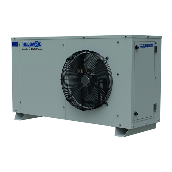
Hermetic R744 Condensing Units
Model Number:
GCU2020P XB1
ESIE20-02
Installation, Commissioning and
Maintenance Manual
Hubbard Products Ltd. 1-7 Bluestem Road,
Ransomes Europark, Ipswich, Suffolk, IP3 9RR UK
Tel: +44 (0)1473 890522
email: commercial@hubbardproducts.com
www.hubbardproducts.com
Copyright HPL March 2021
P41135 Rev 03
Advertisement
Chapters
Table of Contents

Related Manuals for Daikin GCU2020PXB1


Summary of Contents for Daikin GCU2020PXB1
- Page 1 Page 1 of 179 Hubbard Products Ltd Hermetic R744 Condensing Units Model Number: GCU2020P XB1 ESIE20-02 Installation, Commissioning and Maintenance Manual Hubbard Products Ltd. 1-7 Bluestem Road, Ransomes Europark, Ipswich, Suffolk, IP3 9RR UK Tel: +44 (0)1473 890522 email: commercial@hubbardproducts.com www.hubbardproducts.com Copyright HPL March 2021 P41135 Rev 03...
-
Page 2: Table Of Contents
Page 2 of 179 CONTENTS EC Declaration of Conformity Installation, Commissioning and maintenance instructions Material Safety data Sheets Wiring Schematics Pipework Schematics (P&ID) Carel PR300T CO2 Controller manual and factory settings ABB Inverter non-default settings Pressure & Enthalpy Diagram Commissioning Form ECO Design Evaporator Installation Guide Hubbard Products Ltd. -
Page 3: Ec Declaration Of Conformity
Page 3 of 179 1. EC Declaration of Conformity Model: GCU2020PXB1 Part Number: A10145-02M Hubbard Products Ltd. 1-7 Bluestem Road, Ransomes Europark, Ipswich, Suffolk, IP3 9RR UK Tel: +44 (0)1473 890522 email: commercial@hubbardproducts.com www.hubbardproducts.com Copyright HPL March 2021 P41135 Rev 03... - Page 4 Page 4 of 179 Copyright HPL March 2021 P41135 Rev 03...
-
Page 5: Installation, Commissioning And Maintenance
Page 5 of 179 Hubbard Hermetic Rotary R744 Units Installation, Commissioning and Maintenance Manual Model No.: GCU2020PXB1 ESIE20-02 Copyright HPL March 2021 P41135 Rev 03... - Page 6 Page 6 of 179 Contents Safety recommendations Storage Description of the unit Application Handling Post Transport Checks Overall Dimensions Serial plate Information Installation Spacing External Pipe and Electrical Connections Basic Component layout Mechanical Safety of the system Commissioning and Maintenance Service and Maintenance 15.
- Page 7 Page 7 of 179 These pages contain important safety information. Please read carefully before commencing any work on the equipment to which the instructions refer. It is assumed that installation, commissioning, service and maintenance activities must only be undertaken only by competent personnel who have been trained for the activity.
- Page 8 Page 8 of 179 2. Storage Equipment should be stored, prior to installation, in warm, dry conditions, free from dust, vibration and extremes of temperature and humidity. 3. Description of the unit Hubbard CO2 hermetic rotary series includes air-cooled condensing units. They consist of: 1.
- Page 9 Page 9 of 179 Handling The unit shall be handled by appropriate lifting and transport means. An appropriate risk assessment should be undertaken by a suitably qualified person before attempting to move or lift the equipment. M ake sure that no one is in transit in the operating area of the lifting/ transport m eans to prevent any possible accidents to people.
- Page 10 Page 10 of 179 Dim ensions and w eights: Models: GCU2020PXB1 7.1 P ackaged Unit 7.2. Unit Dim ensions Copyright HPL March 2021 P41135 Rev 03...
- Page 11 Page 11 of 179 7.3. W eights Models: GCU2020PXB1 Packaged weight: 175 kg Unit Dry weight: 151 kg Serial P late I nform ation The unit is supplied with necessary warning and attention plates. Serial plate is supplied with the weight of the unit and other information as showing below.
- Page 12 The unit is delivered with positive pressure, please make sure that you release pressure before cutting the pipes. P ipe Sizes: GCU2020PXB1 : Suction Line: 3/8’’ Liquid Line: 3/8’’ Mains electrical supply should be connected by drilling the cover plate as shown below. Secure main cable and avoid scratches on mains cable.
- Page 13 Page 13 of 179 The incoming three phase is connected to the main isolator as shown below. For GCU2020PXB1 unit an incoming cable size of not less than 1.5 mm is recommended. However, cable run and voltage drop need to be consinder.
- Page 14 Page 14 of 179 Basic com ponent layout M echanical Safety of the system Pressure relief valves and pressure switches are installed on the unit accordingly to EN 378. Pressure relief valves are rated as below: Max Allowable Pressures (PS): •...
- Page 15 Page 15 of 179 Com m issioning and M aintenance of Hubbard Herm etic CCUs These instructions, recommendations are provided as a guide for the commissioning and maintenance of units supplied by Hubbard Products Limited. These should be used in conjunction with your company’s health and safety regulations, written work instructions and working practises to ensure that equipment is installed in a safe working manner.
- Page 16 Page 16 of 179 Procedure: Testing by visual examination, and a proprietary bubble solution. Ensure your supply cylinder of Oxygen Free Nitrogen (OFN) is fitted with a pressure limiting device set at just above your maximum test pressure value. Never move a cylinder with a regulator fitted.
- Page 17 Page 17 of 179 13.3 Evacuation Before starting the vacuum procedure it is necessary to open by hand the high pressure valve (HPV), see section 11 above. Also you can refer to P&ID attached in this maunal. For this operation the magnetic tool shown below needs to be used.
- Page 18 Page 18 of 179 4. Replace compressor fuses or switch on circuit breaker for the lead compressor only to ensure all systems are refrigerating during commissioning. 5. If additional oil is needed, please add through the valve in 1st stage suction line. You can find more details in oil charge section.
- Page 19 Page 19 of 179 5. When this stage is reached, the unit can now be left running on full automatic operation, commissioning sheets checked and completed-Section 9. The plant should be allowed to run for a further few days and then a further check made of all controls and any minor adjustments made.
- Page 20 Page 20 of 179 In case install outdoor unit above indoor unit provide oil trap as shown below (1 oil trap at 5m is recommended). 14.2 Changing the Com pressor Oil Refrigeration oil is of bright, transparent appearance even after extended operation. However, various conditions of the system can affect the oil such as insufficient evacuation of the system on start up, dirt from the pipework on installation and excessive discharge temperatures.
- Page 21 Mechanically Isolate the Compressor 4. Undo any pipe clamps of pipework running to the compressor. 5. Unsweat/Debraze pipe connections below. GCU2020PXB1 : For Model 6. Undo 3 off M8 screws using 13mm socket. 7. Rotate compressor so connections are clear of pipework and lift out, when fitting new compressor ensure metal sleeves are fitted in the rubber compressor feet prior to bolting the compressor down to the base plate.
- Page 22 Page 22 of 179 14.5 P ressure R elief Valve/ s 1. Pressure relief valves are preset to discharge at a set pressure dependant on placement within the circuit. No attempt should be made to adjust this setting or to check the setting by discharging the valve. Valves should be removed before testing to a value in excess of 80% of the valve setting.
- Page 23 L) If the evaporator volume is not known, the following estimation can be used: For GCU2020PXB1 unit: 1.5 kg refrigerant at evaporator (estimation based on full capacity load of the condensing unit. ** Hubbard Products Ltd recommends connection with 2 remote evaporators. In case more than two evapoartors plan to be connected with the unit please contact Hubbard technical.
- Page 24 1.72 required (kg) The GCU2020PXB1 unit is delivered with 0.7 kg of oil. The additional oil required for varies pipe length is shown in table above. The additional oil can be added in the system from the valve showing below.
- Page 25 Page 25 of 179 It is recommended that the oil charge should take place before the refrigerant charge. The above estimations of oil charge can be used as guidelines. In case more oil need to be charged into the system after we have charge the refrigerant a number of steps should be follow as shown below.
- Page 26 Page 26 of 179 Materials in the System Refrigerant R744 R-744 is odourless, heavier than air and is an asphyxiate. The refrigerant concentration limit of R-744 is lower than HFCs because of its potential for high toxicity The table below summarises the effect of CO2 at various concentrations in air. PPM of R744 Effect Concentration in atmosphere...
-
Page 27: Material Safety Data Sheets
Page 27 of 179 R-744 Material Safety Data Sheet R-744 1. CHEMICAL PRODUCT AND COMPANY IDENTIFICATION PRODUCT NAME: R-744 OTHER NAME: Carbon Dioxide USE: Refrigerant gas DISTRIBUTOR: National Refrigerants, Inc. 661 Kenyon Avenue Bridgeton, New Jersey 08302 FOR MORE INFORMATION CALL: IN CASE OF EMERGENCY CALL: (Monday-Friday, 8:00am-5:00pm) CHEMTREC: 1-800-424-9300... - Page 28 Page 28 of 179 R-744 DELAYED EFFECTS: No harm expected to healthy individuals. Where competent medical authority deems that such illness would be aggravated by exposure to carbon dioxide, persons in ill health should be restricted from working with or handling. OTHER EFFECTS OF OVEREXPOSURE: Damage to retinal or ganglion cells and central nervous system may occur.
- Page 29 Page 29 of 179 R-744 EXTINGUISHING MEDIA: Use any standard agent – choose the one most appropriate for type of surrounding fire (material itself is not flammable) UNUSUAL FIRE AND EXPLOSION HAZARDS: Carbon Dioxide cannot catch fire. Heat of fire can build pressure in cylinder and cause it to rupture. No part of the container should be exposed to a temperature higher than 125˚F.
- Page 30 Page 30 of 179 R-744 8. EXPOSURE CONTROLS / PERSONAL PROTECTION ENGINEERING CONTROLS: Use local exhaust system, if necessary, to keep the concentration of carbon dioxide below all applicable exposure limits. Under certain conditions, general exhaust ventilation may be acceptable to keep carbon dioxide below the exposure limit PERSONAL PROTECTIVE EQUIPMENT SKIN PROTECTION: Wear insulated neoprene gloves and safety shoes for handling cylinders.
- Page 31 Page 31 of 179 R-744 DECOMPOSITION TEMPERATURE Not available VISCOSITY: Not applicable FLASH POINT: Not applicable (Flash point method and additional flammability data are found in Section 5.) 10. STABILITY AND REACTIVITY NORMALLY STABLE: The product is stable. CONDITIONS TO AVOID: Contact with incompatible materials, exposure to electrical discharges and or high temperatures listed below.
- Page 32 Page 32 of 179 R-744 SKIN: No harm expected from vapor. Prolonged contact with carbon dioxide could cause frostbite. Cold gas or liquid may cause severe frostbite. EYES: No harm expected from vapor. Prolonged contact with carbon dioxide could cause frostbite. Cold gas or liquid may cause severe frostbite.
- Page 33 Page 33 of 179 R-744 15. REGULATORY INFORMATION Users of this product are solely responsible for compliance with all applicable federal, state, and local regulations. TOXIC SUBSTANCES CONTROL ACT (TSCA) TSCA INVENTORY STATUS: Listed on the TSCA inventory SARA TITLE III / CERCLA “Reportable Quantities”...
- Page 34 Page 34 of 179 SAFETY DATA SHEET according to Regulation (EC) No. 1907/2006 DAPHNE HERMETIC OIL PZ68S Version Revision Date: SDS Number: Date of last issue: - 15.03.2017 100000003198 Date of first issue: 15.03.2017 SECTION 1: Identification of the substance/mixture and of the company/undertaking 1.1 Product identifier Trade name : DAPHNE HERMETIC OIL PZ68S...
- Page 35 Page 35 of 179 Revision Date: 15.03.2017 32450621 - DAPHNE HERMETIC OIL PZ68S Precautionary statements Prevention: P261 Avoid breathing dust/ fume/ gas/ mist/ vapours/ spray. P273 Avoid release to the environment. P280 Wear protective gloves. Response: P333 + P313 If skin irritation or rash occurs: Get medical advice/ attention.
- Page 36 Page 36 of 179 Revision Date: 15.03.2017 32450621 - DAPHNE HERMETIC OIL PZ68S fumes from overheating or combustion. If symptoms persist, call a physician. In case of skin contact : Take off contaminated clothing and shoes immediately. Wash off with soap and plenty of water. In case of eye contact : Flush eyes with water as a precaution.
- Page 37 Page 37 of 179 Revision Date: 15.03.2017 32450621 - DAPHNE HERMETIC OIL PZ68S Advice on safe handling : For personal protection see section 8. No special handling advice required. Advice on protection against : Normal measures for preventive fire protection. fire and explosion Hygiene measures : General industrial hygiene practice.
- Page 38 Page 38 of 179 Revision Date: 15.03.2017 32450621 - DAPHNE HERMETIC OIL PZ68S Melting point : No data available Drop point : No data available Pour point : -50.0 °C Boiling point : No data available Flash point : 216 °C Method: Cleveland open cup Evaporation rate : No data available...
- Page 39 Page 39 of 179 Revision Date: 15.03.2017 32450621 - DAPHNE HERMETIC OIL PZ68S 10.4 Conditions to avoid Conditions to avoid : No data available 10.5 Incompatible materials Materials to avoid : Strong bases 10.6 Hazardous decomposition products No hazardous decomposition products are known. SECTION 11: Toxicological information 11.1 Information on toxicological effects Acute toxicity...
- Page 40 Page 40 of 179 Revision Date: 15.03.2017 32450621 - DAPHNE HERMETIC OIL PZ68S Remarks: No data available SECTION 12: Ecological information 12.1 Toxicity Components: tris(methylphenyl) phosphate: M-Factor (Acute aquatic toxicity) 12.2 Persistence and degradability No data available 12.3 Bioaccumulative potential No data available 12.4 Mobility in soil No data available...
- Page 41 Page 41 of 179 Revision Date: 15.03.2017 32450621 - DAPHNE HERMETIC OIL PZ68S 14.5 Environmental hazards Not regulated as a dangerous good 14.6 Special precautions for user Not applicable 14.7 Transport in bulk according to Annex II of MARPOL 73/78 and the IBC Code Not applicable for product as supplied.
- Page 42 Page 42 of 179 Revision Date: 15.03.2017 32450621 - DAPHNE HERMETIC OIL PZ68S A Chemical Safety Assessment is not required for this substance. SECTION 16: Other information Full text of H-Statements H315 : Causes skin irritation. H317 : May cause an allergic skin reaction. H361 : Suspected of damaging fertility or the unborn child.
- Page 43 Page 43 of 179 Revision Date: 15.03.2017 32450621 - DAPHNE HERMETIC OIL PZ68S 10 / 10 Copyright HPL March 2021 P41135 Rev 03...
-
Page 44: Wiring Schematics
Page 44 of 179 4. Wiring Schematics Model: GCU2020PXB1 Part Number: D4154S Hubbard Products Ltd. 1-7 Bluestem Road, Ransomes Europark, Ipswich, Suffolk, IP3 9RR UK Tel: +44 (0)1473 890522 email: commercial@hubbardproducts.com www.hubbardproducts.com Copyright HPL March 2021 P41135 Rev 03... - Page 45 IF IN DOUBT, ASK Page 45 of 179 Rev No Date Title 1-7 Bluestem Road, Ransomes Europark, 2HP MT CCU WIRING DIAGRAM (SHORT FORM) Suffolk, Ipswich, IP3 9RR, Copyright HPL March 2021 P41135 Rev 03 TEL.(01473) 890522 Drawing No. Sheet: Drawn By: Checked By: Date:...
- Page 46 IF IN DOUBT, ASK Page 46 of 179 Rev No Date Title 1-7 Bluestem Road, Ransomes Europark, 2HP MT CCU WIRING DIAGRAM (SHORT FORM) Suffolk, Ipswich, IP3 9RR, Copyright HPL March 2021 P41135 Rev 03 TEL.(01473) 890522 Drawing No. Sheet: Drawn By: Checked By: Date:...
-
Page 47: Pipework Schematics (P&Id)
Page 47 of 179 5. Pipework Schematics Model: GCU2020PXB1 Part Number: D4160 Hubbard Products Ltd. 1-7 Bluestem Road, Ransomes Europark, Ipswich, Suffolk, IP3 9RR UK Tel: +44 (0)1473 890522 email: commercial@hubbardproducts.com www.hubbardproducts.com Copyright HPL March 2021 P41135 Rev 03... - Page 48 IF IN DOUBT, ASK Page 48 of 179 GAS COOLER WITH INTERCOOLER TO GAS TO INTER- FROM INTER- COOLER COOLER COOLER 3/8" FROM COOLER 2-STAGE DISCHARGE 3/8" SWITCH 102/108BAR 3/8" 90 Bar FLASH GAS 1-STAGE VALVE DISCHARGE VALVE CAREL E2V24-C CAREL E2V18-C 3/8"...
- Page 49 Page 49 of 179 6. Carel PR300T CO2 Controller manual and factory settings Copyright HPL March 2021 P41135 Rev 03...
- Page 50 Page 50 of 179 pRack pR300T pRack pR300T user manual for the management of CO systems in transcritical conditions NO POWER & SIGNAL CABLES TOGETHER READ CAREFULLY IN THE TEXT! H i g h E f f i c i e n c y S o l u t i o n s Copyright HPL March 2021 P41135 Rev 03...
- Page 51 Page 51 of 179 IMPORTANT DISPOSAL CAREL bases the development of its products on decades of experience in HVAC, on the continuous investments in technological innovations to products, procedures and strict quality processes with in-circuit and functional INFORMATION FOR USERS ON THE CORRECT HANDLING OF WASTE ELECTRICAL AND ELECTRONIC testing on 100% of its products, and on the most innovative production technology available on the market.
- Page 52 Page 52 of 179 Content 1. INTRODUCTION Main features ..........................5 Components and accessories ..................5 Confi guration of the system and confi guration of the inputs ....and outputs ..........................6 2. HARDWARE CHARACTERISTICS AND INSTALLATION pRack 300 S, M, D, L board description ................7 Technical specifi cations ....................9 pRack pR300T S, M, D, L board dimensions ............
- Page 53 Page 53 of 179 7. PARAMETERS AND ALARMS TABLE Parameter table ........................53 Alarm table ..........................75 I/O Table ............................ 77 8. ALARMS Alarm management ......................83 Compressor alarms ......................83 Pressure and prevent alarms ..................84 9. SUPERVISORY AND COMMISSIONING SYSTEMS PlantVisor PRO and PlantWatch PRO supervisory systems .......
-
Page 54: Introduction
Page 54 of 179 1. INTRODUCTION 1.1 Main features 1.2 Components and accessories pRack pR300T is the integrated CAREL solution for control and The pRack pR300T is available in 4 hardware sizes listed in the table management of CO compressor racks. (for the detailed description of each size, electrical characteristics and installation, refer to Chapter 2): The main features and compressor management characteristics of pRack... -
Page 55: Confi Guration Of The System And Confi Guration Of The Inputs
Page 55 of 179 Accessories: Example 2: 2 suction lines on the same board with scroll or piston compressors, 1 high pressure line: Code Description PGDERK1FX0 pGD evolution user terminal for pRack pR300T Module to convert a 0...10V analog output to an SPDT CONVONOFF0 digital output CVSTDUTLF0... -
Page 56: Hardware Characteristics And Installation
Page 56 of 179 2. HARDWARE CHARACTERISTICS AND INSTALLATION 2.1 pRack 300 S, M, D, L board description pRack pR300T S 13 14 J1 5 J1 2 J1 3 J1 4 J11 pLAN J2 5 BMS2 J2 6 FBus2 pR300T FieldBus card B M S card Fig. - Page 57 Page 57 of 179 pRack pR300T D J1 7 J1 2 J1 3 J1 4 J11 pLAN J2 5 BMS2 J26FBus2 pR300T FieldBus card B M S card Fig. 2.c Key: Ref. Description Ref. Description Power supply connector [G(+), G0(-)] Reserved +Vterm: power supply for additional terminal Reserved...
-
Page 58: Technical Specifi Cations
Page 58 of 179 2.2 Technical specifi cations 2.2.1 Physical specifi cations SMALL 13 DIN modules 110 X 227,5 X 60 mm Dimensions MEDIUM, LARGE 18 DIN modules 110 X 315 X 60 mm BUILT-IN DRIVER 18 DIN modules 110 X 315 X 75 mm Assembly fi tted on DIN rail in accordance with DIN 43880 CEI EN 50022 Material... - Page 59 Page 59 of 179 2.2.3 Universal inputs/outputs U... Analogue inputs, SMALL MEDIUM/ BUILT-IN LARGE Lmax = 30 m DRIVER - CAREL NTC probes (-50T90°C; R/T 10 kΩ±1% at 25°C); (maximum number) - HT NTC (0T150°C); - PTC (600Ω to 2200Ω) - PT500 (-100T400°C) - PT1000 (-100T400°C) - PT100 probes (-100T200°C) 3 (2 on U1...U5,...
- Page 60 Page 60 of 179 2.2.6 Analogue outputs Y... Type 0 to 10 V optically-isolated on Y1...Y6 Lmax 30 m SMALL, MEDIUM/ BUILT-IN DRIVER Y1...Y4, 0 to 10 V Maximum number LARGE Y1...Y6, 0 to 10 V Power supply external 24 Vac (+10/-15%) or 28 to 36 Vdc on VG(+), VG0(-) Precision Y1...Y6 ±...
- Page 61 Page 61 of 179 2.2.9 Serial port Use AWG 20-22 twisted pair shielded cable for the +/- Serial Type/connectors Features Serial ZERO pLAN/J10, J11 • Integrated on main board • HW driver: asynchronous half duplex RS485 pLAN • Not optically-isolated •...
- Page 62 Page 62 of 179 2.2.11 Meaning of the inputs/outputs on the pRack pR300T S, M, L boards Version Connector Signal Description +24 Vdc or 24 Vac power supply J1-1 J1-2 power supply reference J2-1 universal analogue input 1 (NTC, 0 to 1 V, 0 to 5 V ratiometric, 0…10 V, 0…20 mA, 4…20 mA) J2-2 universal analogue input 2 (NTC, 0 to 1 V, 0 to 5 V ratiometric, 0…10 V, 0…20 mA, 4…20 mA) J2-3...
-
Page 63: Prack Pr300T S, M, D, L Board Dimensions
Page 63 of 179 Version Connector Signal Description J20-6 BC10 common for analogue input 10 J20-7 ID17 digital input no. 17, 24 Vac/Vdc J20-8 ID18 digital input no. 18, 24 Vac/Vdc J20-9 IDC17 common for digital inputs 17 and 18 (negative pole for DC power supply) J21-1 NO14 normally open contact, relay no. -
Page 64: Prack Pr300T General Connection Diagram
Page 64 of 179 2.4 pRack pR300T general connection diagram Small 24 Vac/230 Vdc 0 Vac/Vdc 24 Vac/230 Vac 0 Vac/Vdc 24 Vac/230 Vac 0 Vac/Vdc 24 Vac/230 Vac pGDE pRack 0 Vac/Vdc J1 5 J1 2 J1 3 J1 4 J11 pLAN J2 5 BMS2 J2 6 FBus2... - Page 65 Page 65 of 179 Medium 24 Vac/230 Vdc 0 Vac/Vdc 24 Vac/230 Vac 0 Vac/Vdc 24 Vac/230 Vac 0 Vac/Vdc pGDE pRack J1 6 J1 7 J1 8 J1 2 J1 3 J1 4 J1 5 J11 pLAN J2 5 BMS2 J2 6 FBus2 pR300 pR300...
- Page 66 Page 66 of 179 Large 24 Vac/230 Vac 0 Vac/Vdc 24 Vac/230 Vac pGDE pRack 0 Vac/Vdc J1 5 J1 5 J1 6 J1 7 J1 8 J1 2 J1 3 J1 4 J11 pLAN J2 1 J23 FBus2 J2 5 BMS2 J2 6 FBus2 pR300 pR300...
- Page 67 Page 67 of 179 Driver integrato CAREL E V valve A CAREL E V valve B pGDE pRack shield shield J1 5 J1 6 J1 6 J1 7 J1 8 J1 8 1 1 J1 2 J1 3 J1 4 J11 pLAN J2 5 BMS2 J2 6 FBus2...
- Page 68 Page 68 of 179 Driver esterno (applicabile a S/M/L/D) pGDE pRack J1 5 J1 2 J1 3 J1 4 J11 pLAN J2 5 BMS2 J2 6 FBus2 pR300 pR300 pR300T RS485 BMS connections FieldBus card B M S card 24 Vac 230 Vac 35 VA TRADRFE240...
-
Page 69: Expansion Card
Page 69 of 179 Additional confi guration of the expansion card is possible on Fda01, 2.5 Expansion card under PROGRAMMING F.Settings d.FIELDBUS: From version 3.3.0, an I/O expansion card can be used to provide additional L1-Fieldbus Fda01 analogue and digital channels, ideal when there is a high number of Enable cpCOe: compressors and corresponding alarms, or with complex heat recovery systems that require of numerous temperature sensors in the water and... -
Page 70: Installation
Page 70 of 179 INSTALLATION • 3.1 General installation instructions all the very low voltage connections (analogue and 24 Vac/Vdc digital inputs, analogue outputs, serial bus connections, power supplies) must have reinforced or double insulation from the mains network; 3.1.1 Installation procedure •... - Page 71 Page 71 of 179 3.3.1 Connecting universal NTC temperature sensors 3.3.3 Connecting current pressure probes The analogue inputs are compatible with 2-wire NTC sensors. pRack PR300T can be connected to all CAREL SPK* series active pressure The inputs must be set for NTC Signals from the user terminal or using the probes or any other pressure sensors available on the market with 0…20 default value installation procedure.
-
Page 72: Connecting The Digital Inputs
Page 72 of 179 3.3.5 Connecting 0…10 V active probes 3.4 Connecting the digital inputs PRack PR300T can be connected to 0…10 V sensors. The pRack PR300T features digital inputs for connecting safety devices, The inputs must be set for 0…10 V Signals from the user terminal or using alarms, device status and remote switches. -
Page 73: Connecting The Analogue Outputs
Page 73 of 179 230 Vac digital inputs 3.5.2 Optional modules pRack M, L models have up to two groups of inputs powered at 230 Vac Module for converting a PWM analogue output to a liner 0…10 V 50/60 Hz +10/-15%; each group features two inputs (see paragraph 2.2.1 and 4…20 mA analogue output (code CONV0/10A0) for details). -
Page 74: Plan Electrical Connections
Page 74 of 179 3.6.2 Solid state relay (SSR) digital outputs Models PRK100**C* and PRK100**D* Compact 1 (1) The pRack PR300T also features a Version with solid state relays (SSR) on 1 (8) some models for controlling devices that require an unlimited number of 3 (8, 12, 13) switching cycles and thus would not be supported by electromechanical 5 (8, 12, 13,... -
Page 75: Start Up
Page 75 of 179 4. START UP 4.1 Starting the fi rst time 4.2 Wizard After having correctly installed pRack, a number of preliminary Start up operations are required to confi gure the installation. Select Config.Item: Tutorial: the pRack PR300 confi guration procedure varies WIZARD according to the complexity of the installation: A. - Page 76 Page 76 of 179 The preliminary operations to be performed before confi guration are: Answer YES to the next question which asks if a dedicated pRack board with the boards not connect to the pLAN, power up the second and is present;...
-
Page 77: Advanced Confi Guration
Page 77 of 179 If the settings are correct, you can proceed to install the set values: 4.4.1 Associating the inputs and outputs When using pre-confi gurations and the wizard, pRack PR300T can Wizard Ib3a automatically associate the board’s inputs and outputs with the various Board necessary functions. -
Page 78: User Interface
Page 78 of 179 5. USER INTERFACE 5.1 Graphic terminal Starting in version 3.3.0, the main screen can be modifi ed, both in terms of the probe displayed and the value used, from the menu at: F.SETTINGS The pRack PR300T user interface is represented by the pGDE terminal, b.Language Fb04 panel or built-in versions. -
Page 79: Password
Page 79 of 179 Menu screen An example of a menu screen is shown in the fi gure below: Main menu 5/9= D.Condensers E.Other functions F.Settings Fig. 5.b The top right corner shows the selected item and the current password level (for details see the following paragraph). -
Page 80: Menu Description
Page 80 of 179 5.4 Menu description A.Unit status a.Main info b.Set point c.On/Off B.In/Out a.Status a.Digital in b.Analog in c.Digital out d.Analog out b.Manual op. a.Digital out b.Analog out c.Test a.Digital out b.Analog out C.Compressors a.Line 1 (*) a.I/O status b.Control c.Op. -
Page 81: Functions
Page 81 of 179 FUNCTIONS 6.1 Schematic diagram and system confi gurations used Confi guration 2: 1 a pRack pR300T board for each suction line and 1 pRack pR300T board for control of the high pressure part (gas cooler and The schematic diagram of a transcritical system is shown in the fi gure: HPV, RPRV valves): pLAN 3... -
Page 82: Unit On-Off
Page 82 of 179 Confi guration 4: a pRack pR300T board for managing the two suction Note: certain special conditions or functions in the pRack software lines and a board for control of the high pressure part: cause the unit to shutdown: •... - Page 83 Page 83 of 179 With P+I control, added to the eff ect of the proportional action described For control in Neutral zone, the parameters shown in the fi gure must be above is the integral action, used to achieve a null control error in steady set: operation, as shown in the fi gure: NZ timings...
-
Page 84: Compressors
Page 84 of 179 When entering the Neutral zone, the pRack PR300T software calculates The compressor size refers to its capacity and number of load stages or how the request needs to change in order to exit the Neutral zone at to the inverter presence, therefore diff erent sizes need to be defi ned minimum or maximum output, and applies one of the two values for compressors with the same capacity yet a diff erent number of load... - Page 85 Page 85 of 179 If an alarm is active on compressor 3, the recalculated activation It can be seen that the capacity delivered exactly follows the required thresholds are 10, 30, 70 %. capacity, except when below the minimum capacity of the modulating device.
- Page 86 Page 86 of 179 6.4.4 Starting 6.4.7 Economizer pRack PR300T can manage diff erent types of compressor starting: pRack PR300T can activate the economizer function to boost compressor • Direct effi ciency by injecting vapour. Some of the liquid is taken from the •...
- Page 87 Page 87 of 179 The activation screen resembles the one shown in the fi gure and is used Fixed cycle time to override the outputs relating to the operation of the selected device, The compressor ON time is calculated as the percentage of the cycle time e.g.
-
Page 88: Gas Cooler
Page 88 of 179 Alarms Example 2: minimum modulating output value 0 V, maximum value 10 V, pRack PR300T can manage, in addition to the common alarms for all minimum modulating device capacity 60 %, maximum 100 %. types of compressors (see chapter 8 for details), some specifi c alarms for Digital Scroll™... -
Page 89: Hpv Valve Management
Page 89 of 179 6.5.2 Rotation Note: pRack PR300T can manage rotation of the fans, much in the same way as • the split condenser function can be disabled by parameter if the high described for the compressors, therefore: pressure prevention function is activated. If split condenser is disabled •... - Page 90 Page 90 of 179 The HPV valve is managed according to the zone identifi ed based on the 6.6.8 Control of the receiver pressure through the output temperature and gas cooler pressure. HPV valve If the pressure in the receiver goes below the minimum work pressure In order to defi ne the zones, it is necessary to set the two pressure values set, the dynamic calculated setpoint for the HPV valve can be changed in and P...
-
Page 91: Rprv Valve Management
Page 91 of 179 6.6.9 Summary of inputs, outputs and HPV valve par. 6.7 RPRV valve management The following is a summary table of the inputs/outputs used and the Management of the RPRV valve, which is a PI regulation, is to maintain the parameters with indications of the related confi guration screens. -
Page 92: Intercooler
Page 92 of 179 6.8 Intercooler 6.9 Energy saving pRack pR300T manages the gas cooler much the same way as pRack pRack PR300T can activate energy saving functions by adjusting the PR300 does for the condensers on a second condenser line, and activation suction and condensing pressure set points. -
Page 93: Accessory Functions
Page 93 of 179 6.9.2 Floating suction set point 6.10 Accessory functions For the suction line, the fl oating set point is managed by the supervisor. pRack PR300T can manage several accessory functions. Of these, the The suction pressure set point set by the user is changed by the supervisor economizer and liquid injection have already been described in paragraph in range between a settable minimum and maximum. - Page 94 Page 94 of 179 If no oil level input is present, activation of the solenoid valve occurs Minimum off intermittently for the entire time in which at least one compressor is time oil solenoid active. The opening and closing times of the valve during activation can be set by a parameter.
-
Page 95: Subcooling
Page 95 of 179 Summary of inputs/outputs and oil injection parameters 6.12 Subcooling Mask Description pRack PR300T can control subcooling in two diff erent ways: Bab62 Oil diff erential pressure probe 1 line 1 • Analog inputs with the condensing temperature and the liquid temperature Bab66 Oil diff erential pressure probe 1 line 2 •... -
Page 96: Heat Recovery
Page 96 of 179 6.13 Heat recovery HR1I HR1O HR2I HR2O GC by passed GAS cooler disch disch HR2 ING GC Fig. 6.ap pRack pR300T manages up to two heat recovery functions at the same If the HPV valve set point calculated based on the Gas Cooler temperature time. -
Page 97: Generic Functions
Page 97 of 179 • CFloating condensing without heat recovery: SP=Tout+ΔT (screen Stages Dad06) pRack pR300T can manage up to 5 stage functions, with either direct or • Floating condensing during heat recovery (acting on GC): reverse operation. SP=Tout+Off setGC; where Off setGC> ΔT In both cases a setpoint and diff erential can be set and the operation of •... -
Page 98: Double Line Synchronization (Dss)
Page 98 of 179 This means that before turning on the low temperature line, the DSS 6.14.1 ChillBooster forces at least one of the compressors in the medium temperature L1 pRack PR300T can control the Carel ChillBooster, device used for line to turn on at minimum power. - Page 99 Page 99 of 179 6.16.5 Parallel compressor EVD + pRack pR300T connections: pRack pR300T can enable a line of compressors in parallel to the medium temperature suction line upstream of the RPRV valve using a dedicated 230 Vac 24 Vac board, and starting from version 3.3.0 this board can be enabled via pLAN.
- Page 100 Page 100 of 179 Consequently, the fi rst compressor in the parallel line can be controlled If, on the other hand, the Gas Cooler outlet temperature falls below the by inverter. It is recommended to use a suction pressure set point value activation threshold, the card that manages the parallel compressor no for the parallel line that is the same as the receiver pressure set point for longer receives the enabling signal and thus switches off the parallel...
-
Page 101: Settings
Page 101 of 179 For integrated parallel compression (single compressor), when the For example, if the weekly scheduler requires activation of a function, parallel compressor is active, the reference for calculating the delta will yet a closing period is in progress, and requires deactivation of the same no longer be more the medium temperature line compressor suction function, then the function is deactivated. -
Page 102: Parameters And Alarms Table
Page 102 of 179 7. PARAMETERS AND ALARMS TABLE 7.1 Parameter table "Mask index": indicates the unique address of each screen and therefore the path for reaching the parameters in that screen. For example, to reach the parameters related to the suction pressure probe with mask index Bab01, proceed as follows: B.In./Out. - Page 103 Page 103 of 179 Mask index Display description Description Def. U. of M. Values A. Unit status Aa01 (display Pressure Suction pressure (line 1) … …(**) Sat.Temp. Suction saturated temperature (line 1) … …(**) only) ActualSet Actual setpoint for pressure regulation (with compensations applied, line 1) …...
- Page 104 Page 104 of 179 Mask index Display description Description Def. U. of M. Values Aa34 (display C01, C02, …C12 Time remaining for next compressor startup (line 2) 0…32000 Power delivered from compressor 1 from line 2 (a "!" to the right of the value means that 0…100 only) some form of compressor power forcing is active, e.g., safety times, alarms, startup procedure)
- Page 105 Page 105 of 179 Mask index Display description Description Def. U. of M. Values Aaan (display Reg.var. Value of the regulation variable for the generic function in stage 1 … …(**) Enable Status of the enabling variable for the generic function in stage 1 Not active | Active only) Setpoint...
- Page 106 Page 106 of 179 Mask index Display description Description Def. U. of M. Values Ab05 (display UserSetp. Setpoint set by the user for gas cooler regulation under pressure, proportional regulation … …(**) only) (line 1) ActualSetp. Actual setpoint for gas cooler regulation under pressure, proportional regulation (with …...
- Page 107 Page 107 of 179 Mask index Display description Description Def. U. of M. Values Bab65 Common oil receiver pressure probe position (line 2) U1…U10 (****) Common oil receiver pressure probe type (line 2) 4...20mA ----, 0-1V 0-10V 4...20mA 0-5V --- (display only) Common oil receiver pressure value (line 2) …...
- Page 108 Page 108 of 179 Mask index Display description Description Def. U. of M. Values Bbb06 Oil cool. pump 0.0…100.0 Manual request for oil cooling pump (line 1) Force to Bbb07 Compressor 1 0.0…100.0 Manual request for continuous capacity for compressor 1 (line 2) Force to Bbb08 Oil cool.
- Page 109 Page 109 of 179 Mask index Display description Description Def. U. of M. Values Cab13 Power reduction to 0% min Minimum time to decrease capacity request to 0%, dead zone regulation (suction line 1) 0…9999 time Power reduction to 0% max Maximum time to decrease capacity request to 0%, dead zone regulation (suction line 1) 0…9999 time...
- Page 110 Page 110 of 179 Mask index Display description Description Def. U. of M. Values Caf04 Refrigerant type Type of refrigerant (suction line 1) R744 | R134a R404A | R407C R410A | R507A R290 | R600 R600a | R717 R744 | R728 R1270 | R417A R422D | R413A R422A | R423A...
- Page 111 Page 111 of 179 Mask index Display description Description Def. U. of M. Values The following parameters refer to line 2, for details, see the corresponding parameters for line 1 above Cba01 Alarm 1 compressor 1 DI position (line 2) --- | 01…18 U1…U10 (****) Status (display only)
- Page 112 Page 112 of 179 Mask index Display description Description Def. U. of M. Values Daa18 Gas cooler backup probe position (line 1) ---, U1…U10 (****) Gas cooler backup probe type (line 1) 4...20 mA ---- 0-1 V 0-10 V 4...20 mA 0-5 V --- (display only) Gas cooler backup pressure value...
- Page 113 Page 113 of 179 Mask index Display description Description Def. U. of M. Values Daf04 Refrigerant type Type of refrigerant (condensing line 1) R744 | R134a R404A | R407C R410A | R507A R290 | R600 R600a | R717 R744 | R728 R1270 | R417A R422D | R413A R422A | R423A...
- Page 114 Page 114 of 179 Mask index Display description Description Def. U. of M. Values Dbd01 Enable condensing setpoint Enable setpoint compensation (condensing line 2) NO | YES compensation … … … … … … Dbe01 Cond.pressure Condensing high pressure/temperature alarm threshold type (line 2) absolute absolute high alarm...
- Page 115 Page 115 of 179 Mask index Display description Description Def. U. of M. Values Eeaa1a Common oil receiver pressure probe position (line 1) U1…U10 (****) Common oil receiver pressure probe type (line 1) 4...20mA ----, 0-1V - 0-10V- 4...20mA- 0-5V --- (display only) Common oil receiver pressure value (line 1) …...
- Page 116 Page 116 of 179 Mask index Display description Description Def. U. of M. Values Eeab11 Pump Management Setpoint: Setpoint if HR1 pump is regulated by temperature °C/°F Kp if HR1 pump is regulated by temperature %/°C Integral time: Integral time if HR1 pump is regulated by temperature Eeab13 HR1 enable HR probe temp.
- Page 117 Page 117 of 179 Mask index Display description Description Def. U. of M. Values Efb09 High alarm High alarm enabling for generic modulating function 1 disable disable | enable High alarm High alarm threshold for generic modulating function 1 0.0 °C …...
- Page 118 Page 118 of 179 Mask index Display description Description Def. U. of M. Values Ehb06 Enable pump down Enable pump down with at least one LT compressor active NO | YES Threshold Pump down threshold 1.5 barg … … (**) Eia01 RPRV tank pressure probe position ---, U1…U10 (****)
- Page 119 Page 119 of 179 Mask index Display description Description Def. U. of M. Values Eib25 Threshold Receiver high pressure threshold alarm 45.0 barg … … (**) Diff . Receiver high pressure diff erential alarm 5.0 barg … … (**) Delay Receiver high pressure alarm delay 0…9999 Reset...
- Page 120 Page 120 of 179 Mask index Display description Description Def. U. of M. Values … … … … … … Ecba01 Discharge temperature probe position, compressor 1 (line 2) --- | U1…U10 (****) Discharge temperature probe type, compressor 1 (line 2) 4...20 mA --- | NTC | PT1000 0...1 V | 0...10 V |...
- Page 121 Page 121 of 179 Mask index Display description Description Def. U. of M. Values Fca01 Address Address of the supervisory system (line 1) 0…207 Protocol Supervisor communication protocol (line 1) Carel slave --, CAREL SLAVE local LOCAL CAREL SLAVE REMOTE MODBUS SLAVE pRACK MANAGER CAREL SLAVE GSM...
- Page 122 Page 122 of 179 Mask index Display description Description Def. U. of M. Values I.Setup Ib01 Type of system Type of system Aspiraz + Suction Condens. Condenser Suction + Condenser Ib02 Units of meas. Units of measure °C/barg °C | barg | °F | psig Ib03 Compressor type Type of compressors (line 1)
- Page 123 Page 123 of 179 Mask index Display description Description Def. U. of M. Values Ib75 Enable stages and stages for compressor group 1 (line 1) NO | YES 100 | 50/100 | 50/75/100 | 25/50/75/100 | 33/66/100 … … … …...
-
Page 124: Alarm Table
Page 124 of 179 7.2 Alarm table pRack pR300T can manage both alarms relating to the status of the digital inputs and to system operation, similar to the pRack pR300. For each alarm, the following are controlled: • The actions on the devices, if necessary •... - Page 125 Page 125 of 179 Code Description Reset Delay Alarm relay Action ALCad High oil sump temperature, Digital Scroll™ Man./Autom. Confi g. Shutdown compressor ALCae High discharge temperature, Digital Scroll™ Man./Autom. Confi g. Shutdown compressor ALCaf High oil dilution, Digital Scroll™ Man./Autom.
-
Page 126: I/O Table
Page 126 of 179 7.3 I/O Table The list of pRack pR300T inputs and outputs is reported below. Digital inputs Line 1 Mask index Description Channel Logic Notes Ac05, Baack ON/OFF unit, line 1 Baa56, Caaah Common low pressure switch, line 1 Baada, Caa14 Compressor inverter warning, line 1 Baa02, Caa01... - Page 127 Page 127 of 179 Mask index Description Channel Logic Notes Eaaa56 Minimum receiver oil level, line 1 Eaaa57 Oil level compressor 1 line 1 Eaaa58 Oil level compressor 2 line 1 Eaaa59 Oil level compressor 3 line 1 Eaaa60 Oil level compressor 4 line 1 Eaaa61 Oil level compressor 5 line 1 Eaaa62...
- Page 128 Page 128 of 179 Mask index Description Channel Logic Notes Baace Heat recovery, line 2 Baadg, Egba01 ChillBooster fault, line 2 Baade Enable fl oating condenser, line 2 Baacm, Cbd06, Dbd08 Setpoint compensation, line 2 Baacn pRack automatic or manual operation status Dba52 Anti noise, line 2 Dba53...
- Page 129 Page 129 of 179 Mask index Description Channel Logic Notes Line relay compressor 12 line 1 Bac66, Caaae Partwinding/ Star relay compressor 12 line 1 Delta relay compressor 12 line 1 Bac67, Caaaf Valve 1, compressor 12 line 1 Bac70, Caaag Equalization valve compressor 12 line 1 Bacbt, Daa21 Fan 1 line 1...
- Page 130 Page 130 of 179 Mask index Description Channel Logic Notes Line relay compressor 7 line 2 Bacan, Cba80 Partwinding/ Star relay compressor 7 line 2 Delta relay compressor 7 line 2 Bacao, Cba81 Valve 1, compressor 7 line 2 Bacap, Cba82 Valve 2, compressor 7 line 2 Bacar, Cba83 Equalization valve compressor 7 line 2...
- Page 131 Page 131 of 179 Analog inputs Line 1 Mask index Description Channel Logic Notes Bab01, Caaal Suction pressure probe line 1 Bab02, Caaam Suction pressure backup probe type line 1 Bab03, Caaao Suction temperature probe line 1 Bab60 Suction pressure probe compensation line 1 Bab04, Daa39 Gas cooler pressure probe line 1 Bab09, Daa40...
-
Page 132: Alarms
Page 132 of 179 8. ALARMS pRack PR300T can manage both alarms relating to the status of the digital Note: A maximum of 50 alarms can be logged; after this limit any inputs and to operation of the system. For each alarm, the following are new events overwrite the oldest ones, which are therefore deleted. -
Page 133: Pressure And Prevent Alarms
Page 133 of 179 According to the number of alarms selected, the default associated 8.3 Pressure and prevent alarms descriptions will be as shown in the table. pRack PR300T can manage pressure alarms from a pressure switch or probe, according to the following diagram. L1-Alarms ALC90 Alarms from pressure switch:... - Page 134 Page 134 of 179 Prevent by activating heat recovery 8.3.2 Pressure alarms from probe The parameters corresponding to this function can be set in branch The parameters corresponding to these alarms can be set in branch G.b.a/G.b.b of the main menu, if the heat recovery function is present. C.a.e/C.b.e of the main menu for the suction pressure and D.a.e/D.b.e for As well as enabling the function, an off set from the activation threshold the condensing pressure.
-
Page 135: Supervisory And Commissioning Systems
Page 135 of 179 9. SUPERVISORY AND COMMISSIONING SYSTEMS pRack PR300T can be connected to various supervisory systems, 9.2 Commissioning software specifi cally the Carel and Modbus communication protocols can be used. pRack Manager is confi guration and real-time monitoring software used For the Carel protocol, the PlantVisor PRO and PlantWatch PRO models to check the operation of pRack PR300T, for commissioning, debug and are available. -
Page 136: Software Update And Configuration
Page 136 of 179 10. SOFTWARE UPDATE AND CONFIGURATION 10.1 Smart Key: operating instructions Meanings of Buttons/Symbols Flashing: The key is connecting to the pRack. During this phase, which may last a few seconds, the start button is disabled. start Flashing: The key has detected the pRack and is checking the access rights. -
Page 137: Prack Manager: Operating Instructions
Page 137 of 179 10.2 pRack Manager: operating instructions 10.2.1 IInstalling the application to update the software Select the directory containing the application program fi les and click pRack Manager is a program that lets you manage all the confi guration, “Upload”... -
Page 138: Pendrive: Operating Instructions
Page 138 of 179 • Enter the new value (e.g. 3) and click OK. The new value will appear <nomeApplicativo>.BIN [<ApplicationName>.BIN] (download reserved) • in the column marked “scritto” [written]. To write the parameter to the <nomeApplicativo>.DEV [<ApplicationName>.DEV] • pRack controller, right-click and select “scrivi selezionate” [write selected]. <nomeApplicativo>.GRT [<ApplicationName>.GRT] (upload only, from The new value will appear in the column marked “scritto”... - Page 139 Page 139 of 179 Menu access After the description of the desired function, various options are available: The following are the steps for accessing the pendrive management To copy the complete contents of the directory, simply write the menu. Procedure: name of the directory (e.g.
- Page 140 Page 140 of 179 Example: The following fi le will upload the BIOS and an application. At the end a message will ask the user to remove the pendrive. [FUNCTION] Upload application [DIR] NEW AHU Fig. 10.q [NAM] 10.3.4 Upload in autorun mode Uploading in autorun mode is a special case of uploading in automatic BIOS+APPL+LOGSv58B36 mode.
- Page 141 Page 141 of 179 Important: As can be seen, when updating the BIOS and the application, the pGDE terminal shows the message “NO LINK”, meaning that no connection is established. Do not remove the terminal and wait for the end of the update procedure, when the pGDE terminal replicates the messages on the built-in display.
-
Page 142: Confi Guring Pcoweb/Pconet From A System Screen
Page 142 of 179 Example: On the controller with address 1, the autorun fi le will create N e t m a s k a directory called BKP00_01 and copy the fi les APPL_PRack.DWL and FILE_DEV.DEV to this directory. G a t e w a y Connecting to a computer Connect the slave USB port on the controller to the USB port on the D N S 1 :... -
Page 143: Appendix
Page 143 of 179 11. APPENDIX A.1.2 Setting the pRack pR300T board address A.1 System confi gurations with more than The pLAN address of the pRack boards can be set from any pGD1 terminal, one pLAN board using the following procedure: If the system confi guration involves the connection of more than one set address 0 on the terminal (see the previous paragraph for details board in a pLAN, the addresses must be set correctly before selecting a... - Page 144 Page 144 of 179 Copyright HPL March 2021 P41135 Rev 03...
- Page 145 Page 145 of 179 Agenzia / Agency: CAREL INDUSTRIES - Headquarters Via dell’Industria, 11 - 35020 Brugine - Padova (Italy) Tel. (+39) 049.9716611 - Fax (+39) 049.9716600 e-mail: carel@carel.com - www.carel.com Copyright HPL March 2021 P41135 Rev 03...
- Page 146 Page 146 of 179 FULL CAREL PARAMETERS LIST WARNING: Although every attempt to ensure parameters are correct, it is ultimately the Installer and or the Commissioning Engineers responsibility to check and ensure the correct parameters have been programmed and tested. MASK INDEX DESCRIPTION...
- Page 147 Page 147 of 179 FULL CAREL PARAMETERS LIST MASK INDEX DESCRIPTION VALUE TYPE CHANNEL OFFSET ADJUSTED Dab01 Fans regulation type PROPORTIONAL BAND Dab01 Fans control mode TEMPERATURE Dab02 Minimum condensing setpoint °C Dab02 Maximum condensing setpoint °C Dab03 condensing setpoint °C Dab04 Fan can work only when at least one compressor work...
- Page 148 Page 148 of 179 FULL CAREL PARAMETERS LIST MASK INDEX DESCRIPTION VALUE TYPE CHANNEL OFFSET ADJUSTED Cae22 Compressors alarm 7 delay Cae22 Alarm 7 of compressor start delay Cae22 Compressor alarm 7 type(0.Auto 1.Manual) AUTO Cae22 Compressor alarm 7 priority (0=Light - 1=Serious) SERIOUS Cae24 Relative suction setpoint high alarm...
- Page 149 Page 149 of 179 FULL CAREL PARAMETERS LIST MASK INDEX DESCRIPTION VALUE TYPE CHANNEL OFFSET ADJUSTED Cbb08 Decreasing zone differential for compressors regulation (neutral zone) barg Cbf11 Sequence of load unloader CpppCppp Cbb12 Compressors neutral zone minimum complete activation time (neutral zone) Cbb12 Compressors neutral zone maximum complete activation time (neutral zone) Cbb13...
- Page 150 Page 150 of 179 FULL CAREL PARAMETERS LIST MASK INDEX DESCRIPTION VALUE TYPE CHANNEL OFFSET ADJUSTED Dbb15 Intercooler neutral zone maximum complete deactivation time (neutral zone) Dbf01 Number of fans Dbf04 condensing refrigerant type Dbf05 Fans rotation type FIFO Dbg01 Fans modulating device type NONE Dbg02...
- Page 151 Page 151 of 179 FULL CAREL PARAMETERS LIST MASK INDEX DESCRIPTION VALUE TYPE CHANNEL OFFSET ADJUSTED Cbe07 Low superheat alarm threshold Cbe07 Low superheat alarm differential Cbe07 Cbe07 Superheat Alarm manual or automatic reset MANUAL Cbe07 Low superheat alarm delay Cbe35 Discharge threshold setpoint °C...
- Page 152 Page 152 of 179 FULL CAREL PARAMETERS LIST MASK INDEX DESCRIPTION VALUE TYPE CHANNEL OFFSET ADJUSTED Bab13 °C Bab62 °C Bab05 Suction pressure barg 4-20mA Bab06 Suction pressure backup barg 4-20mA Bab07 Suction temperature °C Bab71 Bab08 Condensing pressure barg 4-20mA Bab10 Condensing pressure backup...
- Page 153 Page 153 of 179 FULL CAREL PARAMETERS LIST MASK INDEX DESCRIPTION VALUE TYPE CHANNEL OFFSET ADJUSTED Baa09 Alarm 1 of compressor 2 N.C. Baa10 Alarm 2 of compressor 2 N.C. Baa11 Alarm 3 of compressor 2 N.C. Baa12 Alarm 4 of compressor 2 N.C.
- Page 154 Page 154 of 179 FULL CAREL PARAMETERS LIST MASK INDEX DESCRIPTION VALUE TYPE CHANNEL OFFSET ADJUSTED Baadb Compressor inverter warning N.O. Baaar Common pressostat for oil alarm N.C. Baa61 Alarm 1 of compressor 1 N.C. Baa62 Alarm 2 of compressor 1 N.C.
- Page 155 Page 155 of 179 FULL CAREL PARAMETERS LIST MASK INDEX DESCRIPTION VALUE TYPE CHANNEL OFFSET ADJUSTED Baaak Alarm 1 of compressor 9 N.C. Baaal Alarm 2 of compressor 9 N.C. Baaam Alarm 1 of compressor 10 N.C. Baaan Alarm 1 of compressor 11 N.C.
- Page 156 Page 156 of 179 FULL CAREL PARAMETERS LIST MASK INDEX DESCRIPTION VALUE TYPE CHANNEL OFFSET ADJUSTED Baacg Generic digital input G status N.O. Baach Generic digital input H status N.C. Baaci Generic digital input I status N.C. Baacj Generic digital input J status N.C.
- Page 157 Page 157 of 179 FULL CAREL PARAMETERS LIST MASK INDEX DESCRIPTION VALUE TYPE CHANNEL OFFSET ADJUSTED Bac21 Compressor 4 star relay N.O. Bac22 Compressor 4 unloader 1 N.C. Bac23 Compressor 4 unloader 2 N.C. Bac24 Compressor 4 unloader 3 N.C. Bac25 Compressor 4 unloader 4 N.C.
- Page 158 Page 158 of 179 FULL CAREL PARAMETERS LIST MASK INDEX DESCRIPTION VALUE TYPE CHANNEL OFFSET ADJUSTED Bac62 Compressor 11 unloader 1 N.C. Bac63 Compressor 11 unloader 2 N.C. Bac64 Compressor 11 unloader 3 N.C. Bac65 Compressor 11 equalization valve N.O. Bac66 Compressor 12 line relay N.O.
- Page 159 Page 159 of 179 FULL CAREL PARAMETERS LIST MASK INDEX DESCRIPTION VALUE TYPE CHANNEL OFFSET ADJUSTED Bacaf Compressor 5 unloader 4 N.C. Bacag Compressor 5 equalization valve N.O. Bacag Compressor 6 line relay N.O. Bacag Compressor 6 delta relay N.O. Bacah Compressor 6 star relay N.O.
- Page 160 Page 160 of 179 FULL CAREL PARAMETERS LIST MASK INDEX DESCRIPTION VALUE TYPE CHANNEL OFFSET ADJUSTED Bacbv Fan 3 status N.O. Bacbw Fan 4 status N.O. Bacbx Fan 5 status N.O. Bacby Fan 6 status N.O. Bacbz Fan 7 status N.O.
- Page 161 Page 161 of 179 FULL CAREL PARAMETERS LIST MASK INDEX DESCRIPTION VALUE TYPE CHANNEL OFFSET ADJUSTED Bacdu Oil cooler fan status N.O. Bacdv Compressor 1 liquid injection status N.O. DO 07 Bacdw Compressor 2 liquid injection status N.O. Bacdx Compressor 3 liquid injection status N.O.
- Page 162 Page 162 of 179 7. ABB Inverter non default settings ABB inverters are factory set and tested on these units. Further details on ABB installation and set-up available on request. Copyright HPL March 2021 P41135 Rev 03...
- Page 163 Page 163 of 179 2/5/2020 11:48 AM 1 / 3 Device Info ACS380 Type ACS380-04XX-12A6-4 Model ACS380 Serial AMCK205x Drive parameters Index Name Value Unit Default 7. System info Drive configuration 0x0004 NoUnit 0x0000 0xffff 0x0000 11. Standard DIO, FI, FO DIO1 configuration Digital output NoUnit Input...
- Page 164 Page 164 of 179 2/5/2020 11:48 AM 2 / 3 Index Name Value Unit Default Acceleration time 1 70.000 0.000 1800.000 3.000 Deceleration time 1 70.000 0.000 1800.000 3.000 Acceleration time 2 70.000 0.000 1800.000 60.000 Deceleration time 2 70.000 0.000 1800.000 60.000...
- Page 165 Page 165 of 179 2/5/2020 11:48 AM 3 / 3 Index Name Value Unit Default 46. Monitoring/scaling settings Speed scaling 4200.00 0.10 30000.00 1500.00 Frequency scaling 140.00 0.10 1000.00 50.00 Filter time motor speed 20000 Filter time output frequency 20000 Filter time motor torque 20000 Filter time power...
- Page 166 To install the drive to a DIN rail 6. Connect the control cables Move the locking part to the left. Page 166 of 179 Connection procedure — Push and hold the locking button down. Do the connections according to the default control connections of the application ABB MACHINERY DRIVES macro that you select.
- Page 167 7. Start up the drive Warning Fault Description 7510 FBA A communication. Communication lost between drive and fieldbus For information on the user interface, refer to the ACS380 User interface guide Dimensions and weights Page 167 of 179 adapter. (3AXD50000022224 [English]). Weight size AFF6...
- Page 168 Page 168 of 179 8. PRESSURE & ENTHALPY DIAGRAM FOR R744 REFRIGERANT Copyright HPL March 2021 P41135 Rev 03...
- Page 169 2HP Condensing Unit Page 169 of 179 Expansion & Evaporator Copyright HPL March 2021 P41135 Rev 03...
- Page 170 R744 (CO2) P-h Diagram - Subcritical Page 170 of 179 P-h produced by Coolpack Gas cooler stage stage Evaporator Copyright HPL March 2021 P41135 Rev 03...
- Page 171 R744 (CO2) P-h Diagram - Transcritical Page 171 of 179 Gas cooler P-h produced by Coolpack stage stage Evaporator Copyright HPL March 2021 P41135 Rev 03...
- Page 172 Page 172 of 179 9. Commissioning Form Copyright HPL March 2021 P41135 Rev 03...
- Page 173 Page 173 of 179 CO2 Hermetic Rotary Condending Unit COMMISSIONING FORM MODEL SERIAL No DATE: Site address Initial Refrigerant Charge Initial Oil Charge Pipe length to evap. Comments Compressor Oil / Refrigerant ≥ 35 (wt %) Oil Level correct HP switch Crankcase heater Line 1 current amps...
- Page 174 Page 174 of 179 CO2 Hermetic Rotary Condending Unit COMMISSIONING FORM Additional Comments Name: Signature: Date: Copyright HPL March 2021 P41135 Rev 03...
- Page 175 Page 175 of 179 ECO Design Directive 2009/125/EC Refrigerant fluid R744 (CO2) Product Model GCU2020PXB1 Item Symbol Value Unit °C Evaporating temp. Parameters at full load and ambient temperature 32°C Rated cooling capacity 3.39 Rated power input 1.81 1.87 Rated COP −...
- Page 176 Valves. These will need to be installed on the field pipework near the condensing unit in a safe location, this PRV must be securely clamped in position not just connected to the pipework. MT 2 HP Rotary CCU GCU2020PXB1 MT 4 HP Rotary CCU GCU2040PXB1 MEDIUM TEMPERATURE...
- Page 177 67 Bar(g) MAXIMUM INTERMEDIATE MAXIMUM DISCHARGE LIQUID MODEL DESCRIPTION PRESSURE RUNNING RUNNING RATING PRESSURE GCU2020PXB1 MT 2 HP CCU None Fitted 90 Bar(g) 90 Bar(g) 71 Bar(g) GCU2040PXB1 MT 4 HP CCU 120 bar(g) 90 Bar(g) 90 Bar(g) 71 Bar(g) GCU4070PXB1...
- Page 178 LINE COMPONENTS REQUIRED? RATING HCU2020PXB1 HCU2040PXB1 60 Bar(g) 60 Bar(g) 60 Bar(g) 60 Bar(g) GCU2020PXB1 GCU2040PXB1 HCU4070PXB1 HCU5140PXB1 60 Bar(g) 60 Bar(g) 60 Bar(g) 60 Bar(g) GCU4070PXB1 GCU5140PXB1 HIGH PRESSURE SIDE: All Field and Evaporator Pipework, Valves, etc. MUST have a MINIMUM PS...
- Page 179 LINE COMPONENTS REQUIRED? RATING HCU2020PXB1 HCU2040PXB1 90 Bar(g) 90 Bar(g) 90 Bar(g) 90 Bar(g) GCU2020PXB1 GCU2040PXB1 HCU4070PXB1 HCU5140PXB1 80 Bar(g) 80 Bar(g) 80 Bar(g) 80 Bar(g) GCU4070PXB1 GCU5140PXB1 HIGH PRESSURE SIDE: All Field and Evaporator Pipework, Valves, etc. MUST have a MINIMUM PS...
Need help?
Do you have a question about the GCU2020PXB1 and is the answer not in the manual?
Questions and answers