Table of Contents
Advertisement
Quick Links
Advertisement
Table of Contents
Troubleshooting

Related Manuals for ITT GOULDS PUMPS ICO i-FRAME


Summary of Contents for ITT GOULDS PUMPS ICO i-FRAME
- Page 1 Installation, Operation, and Maintenance Manual Model ICO i-FRAME, ICOH i-FRAME...
-
Page 3: Table Of Contents
Table of Contents Table of Contents 1 Introduction and Safety ............................ 4 1.1 Introduction..............................4 1.1.1 Requesting other information ......................4 1.2 Safety ................................ 4 1.2.1 Safety terminology and symbols ..................... 5 1.2.2 Environmental safety........................6 1.2.3 User safety ............................6 1.2.4 Hazardous liquids.......................... - Page 4 Table of Contents 4.6 Piping checklists............................33 4.6.1 General piping checklist ........................ 33 4.6.2 Permitted nozzle loads and torques at the pump nozzles............. 34 4.6.3 Suction-piping checklist......................... 37 4.6.4 Discharge piping checklist......................40 4.6.5 Bypass-piping considerations ....................... 41 4.6.6 Auxiliary-piping checklist ....................... 42 4.6.7 Final piping checklist ........................
- Page 5 7.4 i-ALERT®2 Equipment Health Monitor troubleshooting ................ 100 8 Parts Listings and Cross-Sectional Drawings.................... 101 8.1 Parts list..............................101 9 Local ITT Contacts ............................105 9.1 Local ITT Contacts ..........................105 9.1.1 Regional offices........................... 105 Model ICO i-FRAME, ICOH i-FRAME Installation, Operation, and Maintenance Manual...
-
Page 6: Introduction And Safety
For instructions, situations, or events that are not consid- ered in this manual or in the sales documents, please contact the nearest ITT representative. Always specify the exact product type and identification code when requesting technical information or spare parts. -
Page 7: Safety Terminology And Symbols
Risk of injury and/or property damage. Operating a pump in an inappropriate application can cause over pressurization, overheating, and/or unstable operation. Do not change the service application without the approval of an authorized ITT representative. 1.2.1 Safety terminology and symbols... -
Page 8: Environmental Safety
WARNING: If the product has been contaminated in any way, such as from toxic chemicals or nuclear radi- ation, do NOT send the product to ITT until it has been properly decontaminated and advise ITT of these conditions before returning. - Page 9 1.2 Safety • Always keep the work area clean. • Pay attention to the risks presented by gas and vapors in the work area. • Avoid all electrical dangers. Pay attention to the risks of electric shock or arc flash hazards. •...
-
Page 10: Hazardous Liquids
Personnel requirements These are the personnel requirements for Ex-approved products in potentially explosive atmospheres: • All work on the product must be carried out by certified electricians and ITT-authorized mechanics. Special rules apply to installations in explosive atmospheres. • All users must know about the risks of electric current and the chemical and physical characteristics of the gas, the vapor, or both present in hazardous areas. -
Page 11: Product Approval Standards
Use of equipment unsuitable for the environment can pose risks of ignition and/or explosion. Ensure the pump driver and all other auxiliary components meet the required area classifica- tion at the site. If they are not compatible, do not operate the equipment and contact an ITT representative before proceeding. -
Page 12: Product Warranty
Maintenance manual (IOM) can cause serious personal injury or damage to the equipment. This in- cludes any modification to the equipment or use of parts not provided by ITT Goulds Pumps. If there is any question regarding the intended use of the equipment, please contact an ITT Goulds representative before proceeding. - Page 13 1.5 ATEX Considerations and Intended Use All pumping unit (pump, seal, coupling, motor and pump accessories) certified for use in an ATEX classi- fied environment, are identified by an ATEX tag secured to the pump or the baseplate on which it is mounted.
- Page 14 The code classification marked on the equipment must be in accordance with the specified area where the equipment will be installed. If it is not, do not operate the equipment and contact your ITT Goulds Pumps sales representative before proceeding.
-
Page 15: Transportation And Storage
2 Transportation and Storage 2 Transportation and Storage 2.1 Inspect the delivery 2.1.1 Inspect the package Inspect the package for damaged or missing items upon delivery. Note any damaged or missing items on the receipt and freight bill. File a claim with the shipping company if anything is out of order. If the product has been picked up at a distributor, make a claim directly to the distributor. -
Page 16: Storage Guidelines
Treat bearing and machined surfaces so that they are well preserved. Refer to the drive unit and cou- pling manufacturers for their long-term storage procedures. For questions about possible long-term storage treatment services, please contact your local ITT sales representative. -
Page 17: Product Description
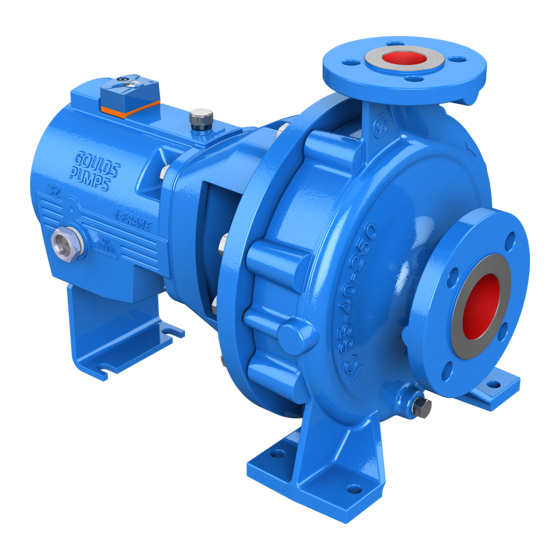
3 Product Description 3 Product Description 3.1 General description The model ICO i-FRAME is a single-stage volute casing pump. Hydraulic design and dimensions comply with ISO 2858/ EN 22858. The technical design complies with ISO 5199/EN 25199. Model ICOH i- FRAME additionally have cooling or heating of the casing cover and/or the volute casing. -
Page 18: General Description I-Alert®2 Equipment Condition Monitor
3.2 General description i-ALERT®2 Equipment Condition Monitor Frame adapter • Provides safe and accurate alignment for the liquid end to the bearing frame. • Large access windows make installation and maintenance of seal and auxiliary support systems trouble-free. Bearings Heavy-duty ball bearings provide L10 bearing life in excess of 17,500 hours. The size of the bearing frame is shown in the data sheet and/or order confirmation. -
Page 19: Nameplate Information
3.3 Nameplate information 3.3 Nameplate information Pump nameplate Figure 3: Pump nameplate Nameplate Field Explanation Serial number of the pump MODEL Pump Model SIZE Size of Pump STD DIM ANSI Std designation – Not applicable ISO Pumps HYDRO PRESS Pump Test Pressure in kPag FLOW Rated pump flow in cubic metres per hour Rated pump speed in revolutions per minute... -
Page 20: Installation
Electrical connections must be made by certified electricians in compliance with all inter- national, national, state and local regulations. • Supervision by an authorized ITT representative is recommended to ensure proper instal- lation. Improper installation may result in equipment damage or decreased performance. 4.1.1 Pump location guidelines WARNING: Safe lifting points are specifically identified in this manual. -
Page 21: Baseplate-Mounting Procedures
4.2 Baseplate-mounting procedures 4.2 Baseplate-mounting procedures 4.2.1 Prepare the baseplate for mounting Remove all the attached equipment from the baseplate. Clean the underside of the baseplate completely. If applicable, coat the underside of the baseplate with an epoxy primer. Use an epoxy primer only if using an epoxy-based grout. Remove the rust-proofing coat from the machined mounting pads using an appropriate solvent. -
Page 22: Install The Baseplate Using Jackscrews
4.2 Baseplate-mounting procedures Shims or wedges Figure 5: Side view Lower the baseplate carefully onto the foundation bolts. Put the machinist's levels across the mounting pads of the driver and the mounting pads of the pump. NOTICE: Remove all dirt from the mounting pads in order to ensure that the correct leveling is achieved. Failure to do so can result in equipment damage or decreased performance. - Page 23 4.2 Baseplate-mounting procedures Item Description Jackscrew Baseplate Foundation Plate Figure 6: Jackscrews Level the driver mounting pads: NOTICE: Remove all dirt from the mounting pads in order to ensure that the correct leveling is achieved. Failure to do so can result in equipment damage or decreased performance. Put one machinist's level lengthwise on one of the two pads.
-
Page 24: Install The Baseplate Using Spring Mounting
4.2 Baseplate-mounting procedures Turn the center jackscrews down so that they rest on their plates on the foundation surface. Level the pump mounting pads: NOTICE: Remove all dirt from the mounting pads in order to ensure that the correct leveling is achieved. Failure to do so can result in equipment damage or decreased performance. - Page 25 4.2 Baseplate-mounting procedures Install the lower part of the spring assembly: Screw the lower jam nut onto the spring stud. Screw the lower adjusting nut onto the spring-stud, on top of the jam nut. Set the lower adjusting nut to the correct height. The correct height depends on the required distance between the foundation/floor and the base- plate.
-
Page 26: Install The Baseplate Using Stilt Mounting
4.2 Baseplate-mounting procedures 4.2.6 Install the baseplate using stilt mounting NOTICE: The stilt-mounted baseplate is not designed to support static piping loads. Ensure that the suc- tion and discharge piping are supported individually. Failure to do so may result in equipment damage. - Page 27 4.2 Baseplate-mounting procedures Mounting plate Mounting nut Stilt bolt Foundation cups Washer Upper adjustment nut Mounting washer Mounting bolt Figure 10: Example of an installed stilt assembly Model ICO i-FRAME, ICOH i-FRAME Installation, Operation, and Maintenance Manual...
-
Page 28: Baseplate-Leveling Worksheet
4.2 Baseplate-mounting procedures 4.2.7 Baseplate-leveling worksheet Level measurements 1)____________________ 2)____________________ 3)____________________ 4)____________________ 5)____________________ 6)____________________ 7)____________________ 8)____________________ 9)____________________ 10)___________________ 11)___________________ 12)___________________ 13)___________________ 14)___________________ 15)___________________ 16)___________________ 17)___________________ 18)___________________ Model ICO i-FRAME, ICOH i-FRAME Installation, Operation, and Maintenance Manual... -
Page 29: Install The Pump, Driver, And Coupling
4.3 Install the pump, driver, and coupling 4.3 Install the pump, driver, and coupling Mount and fasten the pump on the baseplate. Use applicable bolts. Mount the driver on the baseplate. Use applicable bolts and hand tighten. Install the coupling. See the installation instructions from the coupling manufacturer. -
Page 30: Permitted Indicator Values For Alignment Checks
4.4 Pump-to-driver alignment Final alignment (hot alignment) checks When After the first run This ensures correct alignment when both the pump and the driver are at op- erating temperature. Periodically This follows the plant operating procedures. 4.4.2 Permitted indicator values for alignment checks 4.4.2.1 Cold settings for parallel vertical alignment Introduction This section shows the recommended preliminary (cold) settings for electric motor-driven pumps based... -
Page 31: Pump-To-Driver Alignment Instructions
4.4 Pump-to-driver alignment Figure 11: Dial indicator attachment Rotate the pump coupling half (X) in order to check that the indicators are in contact with the driver coupling half (Y) but do not bottom out. Adjust the indicators if necessary. 4.4.5 Pump-to-driver alignment instructions 4.4.5.1 Perform angular alignment for a vertical correction Set the angular alignment indicator to zero at the top-center position (12 o’clock) of the driver cou-... - Page 32 The specified permitted reading values are valid only at operating temperature. For cold set- tings, other values are permitted. The correct tolerances must be used. Failure to do so can result in misalignment. Contact ITT for further information. 4.4.5.4 Perform parallel alignment for a horizontal correction A unit is in parallel alignment when the parallel indicator (P) does not vary by more than as measured at four points 90°...
-
Page 33: Grout The Baseplate
4.5 Grout the baseplate Repeat the previous steps until the permitted reading value is achieved. 4.4.5.5 Perform complete alignment for a vertical correction Set the angular and parallel dial indicators to zero at the top-center position (12 o’clock) of the driver coupling half (Y). - Page 34 4.5 Grout the baseplate Item Description Baseplate Shims or wedges Grout Foundation Sleeve Bolt Figure 12: Pour grout into baseplate Fill the remainder of the baseplate with grout, and allow the grout to set for at least 48 hours. Item Description Baseplate Grout Foundation...
-
Page 35: Piping Checklists
4.6 Piping checklists 4.6 Piping checklists 4.6.1 General piping checklist Precautions WARNING: Risk of premature failure. Casing deformation can result in misalignment and contact with • rotating parts, causing excess heat generation and sparks. Flange loads from the piping system, including those from the thermal expansion of the piping, must not exceed the limits of the pump. -
Page 36: Permitted Nozzle Loads And Torques At The Pump Nozzles
4.6 Piping checklists Check Explanation/comment Checked Check that only necessary fittings are This helps to minimize friction losses. used. Example: Installation for expansion Correct Incorrect This illustration shows a correct installation for expan- This illustration shows an incorrect installation for expan- sion: sion: Expansion loop/joint... - Page 37 4.6 Piping checklists Figure 14: External Forces and Moments on Nozzles Table 2: Suction nozzle Ø Forces in N | lbf Torques in Nm | ft-lb Sizes ΣF ΣM 40-25-160 40 880 | 198 770 | 173 700 | 157 1,370 | 308 900 | 663 630 | 465 740 | 546 1,330 | 981...
- Page 38 4.6 Piping checklists Ø Forces in N | lbf Torques in Nm | ft-lb Sizes ΣF ΣM 125-80-160 125 2,765 | 622 2,485 | 2,240 | 4,350 | 978 1,470 | 1,050 | 774 1,330 | 981 2,140 | 1,084 1,578 125-80-200 125 2,765 | 622 2,485 |...
-
Page 39: Suction-Piping Checklist
4.6 Piping checklists Ø Forces in N | lbf Torques in Nm | ft-lb Sizes ΣF ΣM 80-50-250 50 1,050 | 950 | 214 1,150 | 259 1,820 | 409 980 | 723 700 | 516 800 | 590 1,450 | 1,069 80-50-315 50 1,050 |... - Page 40 4.6 Piping checklists Check Explanation/comment Checked Check that elbows in general do not have See the Example sections for illustrations. sharp bends. — Check that the suction piping is one or two The suction piping must never have a smaller diame- sizes larger than the suction inlet of the ter than the suction inlet of the pump.
- Page 41 4.6 Piping checklists Liquid source above the pump Check Explanation/comment Checked Check that an isolation valve is installed in This permits you to close the line during pump inspec- the suction piping at a distance of at least tion and maintenance. two times the pipe diameter from the suc- Do not use the isolation valve to throttle the pump.
-
Page 42: Discharge Piping Checklist
4.6 Piping checklists Example: Suction piping equipment Correct Incorrect Suction pipe sloping upwards from liquid source Air pocket, because the eccentric reducer is not used and because the suction piping does not Long-radius elbow slope gradually upward from the liquid source Strainer Foot valve Eccentric reducer with a level top... -
Page 43: Bypass-Piping Considerations
When to install a minimum-flow orifice You can size and install a minimum-flow orifice in a bypass line in order to prevent bypassing excessive flows. Consult your ITT representative for assistance in sizing a minimum-flow orifice. When a minimum-flow orifice is unavailable Consider an automatic recirculation control valve or solenoid-operated valve if a constant bypass (mini- mum-flow orifice) is not possible. -
Page 44: Auxiliary-Piping Checklist
4.6 Piping checklists 4.6.6 Auxiliary-piping checklist Precautions CAUTION: • Risk of heat generation, seal failure, and possible physical injury. Sealing systems that are not self-purging or self-venting, such as plan 23, require manual venting prior to operation. • Running a mechanical seal dry, even for a few seconds, can cause seal failure and physi- cal injury. -
Page 45: Commissioning, Startup, Operation, And Shutdown
5 Commissioning, Startup, Operation, and Shutdown 5 Commissioning, Startup, Operation, and Shutdown 5.1 Preparation for startup WARNING: • Risk of serious physical injury or death. Exceeding any of the pump operating limits (e.g. - pressure, temperature, power, etc.) could result in equipment failure, such as explosion, seizure, or breach of containment. -
Page 46: Remove The Coupling Guard
5.2 Remove the coupling guard seal or shaft sleeve damage by ensuring that the seal is properly installed and centered on the sleeve. NOTICE: • Verify the driver settings before you start any pump. Refer to the applicable drive equip- ment IOMs and operating procedures. -
Page 47: Check The Rotation
5.3 Check the rotation Remove the nut, bolt, and washers from the driver half of the coupling guard. Remove the driver half of the coupling guard: Slightly spread the bottom apart. Lift upwards. Remove the remaining nut, bolt, and washers from the pump half of the coupling guard. It is not necessary to remove the end plate from the pump side of the bearing housing. -
Page 48: Install The Coupling Guard
5.5 Install the coupling guard Couplings must have proper certification to be used in an ATEX classified environment. Use the instruc- tions from the coupling manufacturer in order to lubricate and install the coupling. Refer to driver/ coupling/gear manufacturers IOM for specific instructions and recommendations. 5.5 Install the coupling guard WARNING: •... - Page 49 5.5 Install the coupling guard Item Description Annular groove Pump-side end plate Driver Pump half of the coupling guard Figure 15: Guard half installation The annular groove in the coupling guard half must fit around the end plate. Item Description Annular groove End plate (pump end) Guard half...
- Page 50 5.5 Install the coupling guard Item Description Washer Bolt Figure 17: Secure coupling guard half to end plate Put the driver half of the coupling guard in place: Slightly spread the bottom apart. Place the driver half of the coupling guard over the pump half of the coupling guard. The annular groove in the coupling guard half must face the motor.
- Page 51 5.5 Install the coupling guard End plate Driver Figure 19: Placement of driver half of coupling guard Place the driver-side end plate in the annular groove of the driver-half of the coupling guard. Use a bolt, a nut, and two washers to secure the coupling guard half to the end plate. Hand-tighten only.
-
Page 52: Bearing Lubrication
175°C | 347°F Setting point (Pourpoint) -15°C | 5°F Application temperature Higher than permitted bearing temperature (Contact your ITT representative to determine a suitable type of lubrication if ambient temperatures are below -10°C | 14°F. Oil quantity requirements Bearing frame size... - Page 53 5.6 Bearing lubrication If... Then... The pump has an oil level sight glass (stand- Use the "Fill the bearing frame with oil" procedure. ard design) The pump has a constant level oiler (optional) Use the "Fill the bearing frame with an optional oil- er"...
-
Page 54: Lubricating-Grease Requirements
5.7 Shaft-sealing options Bearing frame Oil level sight glass Main body Figure 22: Filling bearing frame oiler Place the O-ring on the reservoir spout. Place your thumb over the reservoir spout. Invert the spout and insert it into the internal threaded boss on the main body. 10. -
Page 55: Mechanical Seal Options
5.7 Shaft-sealing options • Conventional outside-component mechanical seal • Packed-stuffing-box option 5.7.1 Mechanical seal options Pumps are usually shipped with mechanical seals installed. If they are not, then refer to the mechanical seal manufacturer's installation instructions. These are the mechanical seal options for this pump: •... -
Page 56: Pump Priming
5.8 Pump priming You must use an external sealing liquid under these conditions: • The pumped fluid includes abrasive particles. • The stuffing-box pressure is below atmospheric pressure when the pump is running with a suction lift or when the suction source is in a vacuum. Under these conditions, packing is not cooled and lubricated and air is drawn into pump. - Page 57 5.8 Pump priming Open the valve in the outside supply line until only liquid escapes from the vent valves. Close the vent valves. Close the outside supply line. Item Description Discharge isolation valve Shutoff valve From outside supply Foot valve Check valve Figure 24: Pump priming with suction supply below pump with foot valve and an outside supply Model ICO i-FRAME, ICOH i-FRAME Installation, Operation, and Maintenance Manual...
-
Page 58: Other Methods Of Priming The Pump
5.9 Start the pump Item Description By-pass line Shutoff valve Foot valve Check valve Discharge isolation valve Figure 25: Pump priming with suction supply below pump with foot valve using bypass around check valve 5.8.3 Other methods of priming the pump You can also use these methods in order to prime the pump: •... -
Page 59: I-Alert®2 Equipment Health Monitor
5.10 i-ALERT®2 Equipment Health Monitor • Open the suction valve. • Open any recirculation or cooling lines. Fully close or partially open the discharge valve, depending on system conditions. Start the driver. Slowly open the discharge valve until the pump reaches the desired flow. Immediately check the pressure gauge to ensure that the pump quickly reaches the correct dis- charge pressure. -
Page 60: Shut Down The Pump
Always deactivate the health monitor when the pump is going to be shut down for an extended period of time. Failure to do so will result in reduced battery life. Touch and hold a small magnet to the health monitor over the ITT logo until the red LEDs blink three times. -
Page 61: Make The Final Alignment Of The Pump And Driver
5.14 Make the final alignment of the pump and driver 5.14 Make the final alignment of the pump and driver WARNING: • Failure to disconnect and lock out driver power may result in serious physical injury or death. Always disconnect and lock out power to the driver before performing any installa- tion or maintenance tasks. -
Page 62: Maintenance
6 Maintenance 6 Maintenance 6.1 Maintenance schedule Maintenance inspections A maintenance schedule includes these types of inspections: • Routine maintenance • Routine inspections • Three-month inspections • Annual inspections Shorten the inspection intervals appropriately if the pumped fluid is abrasive or corrosive or if the envi- ronment is classified as potentially explosive. -
Page 63: Bearing Maintenance
Replace worn parts. 6.2 Bearing maintenance These bearing lubrication sections list different temperatures of pumped fluid. If your pump is ATEX certified and the pumped fluid exceeds the permitted temperature values, then consult your ITT repre- sentative. Bearing lubrication schedule... -
Page 64: Change The Oil
175°C | 347°F Setting point (Pourpoint) -15°C | 5°F Application temperature Higher than permitted bearing temperature (Contact your ITT representative to determine a suitable type of lubrication if ambient temperatures are below -10°C | 14°F. Oil quantity requirements Bearing frame size... -
Page 65: Regrease The Grease-Lubricated Bearings
6.3 Maintenance schedule 6.2.4 Regrease the grease-lubricated bearings NOTICE: Risk of equipment damage. Ensure that the grease container, the greasing device, and the fit- tings are clean. Failure to do so can result in impurities entering the bearing housing while re- greasing the bearings. -
Page 66: Bearing Maintenance
Replace worn parts. 6.4 Bearing maintenance These bearing lubrication sections list different temperatures of pumped fluid. If your pump is ATEX certified and the pumped fluid exceeds the permitted temperature values, then consult your ITT repre- sentative. Bearing lubrication schedule... -
Page 67: Lubricating Oil Requirements
175°C | 347°F Setting point (Pourpoint) -15°C | 5°F Application temperature Higher than permitted bearing temperature (Contact your ITT representative to determine a suitable type of lubrication if ambient temperatures are below -10°C | 14°F. Oil quantity requirements Bearing frame size... -
Page 68: Regrease The Grease-Lubricated Bearings
Cartridge seals installed by the user require disengagement of the hold- ing clips prior to operation, allowing the seal to slide into place. If the seal has been installed in the pump by ITT, these clips have already been disengaged. Model ICO i-FRAME, ICOH i-FRAME Installation, Operation, and Maintenance Manual... -
Page 69: Packed Stuffing-Box Maintenance
6.5 Shaft seal maintenance Other mechanical seal types For other types of mechanical seals, refer to the instructions provided by the seal manufacturer for instal- lation and setting. Reference drawing The manufacturer supplies a reference drawing with the data package. Keep this drawing for future use when you perform maintenance and seal adjustments. -
Page 70: Disassembly
6.6 Disassembly 6.6 Disassembly 6.6.1 Disassembly precautions WARNING: • Failure to disconnect and lock out driver power may result in serious physical injury or death. Always disconnect and lock out power to the driver before performing any installa- tion or maintenance tasks. •... -
Page 71: Drain The Pump
6.6 Disassembly • Micrometer • Rubber mallet • Screwdriver • Snap-ring pliers • Wrenches • Lifting eyebolt (dependent on pump / motor size) 6.6.3 Drain the pump CAUTION: • Risk of physical injury. Allow all system and pump components to cool before handling. •... -
Page 72: Remove The Coupling Hub
6.6 Disassembly Figure 26: Back pullout removal Remove the hold-down bolts of the bearing frame foot. Remove the casing bolts. WARNING: • Risk of severe physical injury or death from explosion of trapped liquid. Never use heat to remove parts unless explicitly stated in this manual. Tighten the jackscrews evenly, using an alternating pattern, in order to remove the back pull-out as- sembly. -
Page 73: Remove The Impeller
6.6 Disassembly Figure 27: Coupling hub removal 6.6.7 Remove the impeller WARNING: • Risk of severe physical injury or death from explosion of trapped liquid. Never use heat to remove parts unless explicitly stated in this manual. • Risk of serious physical injury or equipment damage. Pump and components are heavy. Ensure all equipment is properly supported while working. - Page 74 6.6 Disassembly Secure the rotor at the end and loosen the impeller nut (right-threaded). Remove the impeller with two screwdrivers or pry bars. Figure 29: Impeller removal method NOTICE: • Remove shaft guard using a prying tool. • Be sure to align the pry bars with the impeller vanes in order to prevent damage to the impeller.
-
Page 75: Remove The Seal-Chamber Cover
6.6 Disassembly Figure 30: Rotor components 6.6.8 Remove the seal-chamber cover Remove the gland stud nuts. Remove the seal-chamber stud nuts. Remove the seal chamber (161). Remove the shaft sleeve (524). The mechanical seal is attached to the sleeve. NOTICE: Be careful with the mechanical seal. -
Page 76: Remove The Stuffing-Box Cover
6.6 Disassembly 412.21 471.61 902.31 920.31 Figure 31: Gland removal 6.6.9 Remove the stuffing-box cover Remove the gland nuts and the gland (452). Remove the stuffing-box-cover nuts. Remove the stuffing-box cover (161). Remove the shaft sleeve (524). Remove shims from shaft (check sleeve to ensure no shims were retained after removal). Remove the packing (461) and lantern ring (458) from the stuffing-box cover (161). - Page 77 6.6 Disassembly Figure 33: Bearing frame cross-section Reach inside the frame and remove the snap ring (932.51) using the designated snap ring pliers. Use snap ring pliers according to DIN 5256-C. Refer to this table for the correct size: Bearing frame size Pliers size Minimum length of pliers 24 i-FRAME 94/C 40 200 mm | 8 in.
-
Page 78: Pre-Assembly Inspections
6.7 Pre-assembly inspections Bearing frame size Pliers size Minimum length of pliers 32, 42 i-FRAME 94/C 85 250 mm | 10 in. 48 i-FRAME 94/C 85 300 mm | 12 in. Remove the shaft (210), with the radial and thrust bearings (320.51 and 320.52) and the bearing nut (923.51) attached, from the bearing frame (330). - Page 79 6.7 Pre-assembly inspections Casing areas to inspect The arrows point to the areas to inspect for wear on the casing: Figure 34: Areas to inspect on the casing Impeller replacement This table shows the criteria for replacing the impeller: Impeller parts When to replace Impeller vanes •...
-
Page 80: Shaft Replacement Guidelines
6.7 Pre-assembly inspections Gaskets, O-rings, and seats replacement WARNING: Risk of death or serious injury. Leaking fluid can cause fire and/or burns. Replace all gaskets and O-rings at each overhaul or disassembly. • Replace all gaskets and O-rings at each overhaul and disassembly. •... -
Page 81: Bearing-Frame Inspection
6.7 Pre-assembly inspections 6.7.3 Bearing-frame inspection Checklist Check the bearing frame for these conditions: • Visually inspect the bearing frame and frame foot for cracks. • Check the inside surfaces of the frame for rust, scale, or debris. Remove all loose and foreign ma- terial. -
Page 82: Bearings Inspection
6.8 Reassembly Figure 38: Seal chamber Figure 39: Stuffing box cover 6.7.5 Bearings inspection Condition of bearings Do not reuse bearings. The condition of the bearings provides useful information on operating conditions in the bearing frame. Checklist Perform these checks when you inspect the bearings: •... - Page 83 6.8 Reassembly NOTICE: • Ensure that the pipe threads are clean. Apply thread sealant to the plugs and fittings. Fail- ure to do so may result in oil leaks and equipment damage. • There are several methods you can use to install bearings. The recommended method is to use an induction heater that heats and demagnetizes the bearings.
- Page 84 6.8 Reassembly snap ring is properly seated in the groove by pressing on the snap ring with a flat head screw- driver. Figure 42: Snap ring detail As a recommendation, thread a stud into one of the four threaded bolt holes in the frame adapt- er (344), and finger tighten only.
-
Page 85: Install The Impeller And Casing
6.8 Reassembly Make sure to position the bolts in the center of the drilled holes in order to ensure the proper oil settings. Tighten according to the Bolt torque values table. Press the inboard (421.41) labyrinth oil seal into the Lantern (344) and the outboard (421.51) labyrinth oil seal into the Bearing Frame (330). - Page 86 6.8 Reassembly Figure 43: Impeller installation Locate and install casing gasket (400) on casing gasket feature. Use vacuum grease or other inert assembly paste to locate gasket in sealing feature. Any compound used must be compatible with pumped fluid. Lower casing (102V) onto back pull-out assembly and tighten casing bolts (901.11) to IOM specified torque values.
-
Page 87: Shaft Sealing
6.8 Reassembly 6.8.3 Shaft sealing WARNING: The mechanical seal used in an Ex-classified environment must be properly certified. CAUTION: Running a mechanical seal dry, even for a few seconds, can cause seal failure and physical injury. Never operate the pump without liquid supplied to the mechanical seal. Before proceeding with seal installation, complete the 6.8.6.4 ICO assembly worksheet on page 95 shim measurement method and installation. - Page 88 (525) thickness required for correct front clearance. 14. Determine gasket type and fluid temperature - record in the provided fields. NOTICE: If using ITT/Goulds K14153A gauge bar kit, see Figure 45: Goulds gauge bar method on page 87, If using a generic bar see...
- Page 89 15. Select an appropriate length gauge bar to match pump features, measure height and record as di- mension "H". 16. If using ITT/GOULDS gauge bar K14153A kit proceed to Step 20. NOTICE: K14153A is a set of gauge bars designed to fit within the gasket sealing feature of ICO casings but is not a required tool.
- Page 90 6.8 Reassembly NOTICE: Casing Gasket (400) must not be installed and feature must be clean and free of foreign mate- rials. 19. Subtract A2 from A1 and record in the A field (A = A1-A2) -- Refer to Figure 46: Generic gauge bar method on page 20.
- Page 91 6.8 Reassembly 29. Using the shim kit provided in the assembly components, determine a combination of shims that matches the calculated shim height Shim pack consists of one of each of the following thicknesses: (mm) (in) (mm) (in) (mm) (in) (mm) (in) 0.025...
- Page 92 6.8 Reassembly Carefully clean the stuffing-box bore. Twist the packing enough to get it around the shaft. Packing rings Lantern rings Packing rings Lantern rings Correct Incorrect Figure 49: Packing rings and lantern rings Insert the packing and stagger the joints in each ring by 90°. Install the stuffing-box parts in this order: One packing ring One lantern ring (two-piece)
- Page 93 6.8 Reassembly Install casing cover (161) on frame adapter (344) - ensure proper orientation with flush tap accessi- ble through top of frame adapter (344). Slide the cartridge seal into the seal chamber and secure using the four studs and nuts. Complete Pump Assembly before tightening seal rotating section set screws and removing center- ing clips.
-
Page 94: Install The Back Pull-Out Assembly
6.8 Reassembly 6.8.4 Install the back pull-out assembly WARNING: Lifting and handling heavy equipment poses a crush hazard. Use caution during lifting and handling and wear appropriate Personal Protective Equipment (PPE, such as steel-toed shoes, gloves, etc.) at all times. Seek assistance if necessary. Clean the casing fit and install the casing gasket (400) on the seal chamber and stuffing-box cover. -
Page 95: Post-Assembly Checks
6.8 Reassembly NOTICE: When a cartridge mechanical seal is used, ensure that the set screws in the seal locking ring are tightened and that the centering clips have been removed prior to startup. This prevents seal or shaft sleeve damage by ensuring that the seal is properly installed and centered on the sleeve. - Page 96 6.8 Reassembly 6.8.6.3 Spare parts Spare pumps kept for stand-by usage When you stock spare, stand-by pumps, consider these guidelines: • In plants where failure of a pump could endanger human life or cause damage to property or high costs, you must keep a sufficient number of stand-by pumps in stock. •...
- Page 97 Select appropriate length gauge bar to match pump features, measure height, record in H = ______ "H". If using ITT/Goulds gauge bar K14153A kit proceed to Step 8. Measure from top of bar to impeller hub feature as shown in Figure 54: Generic gauge...
- Page 98 6.8 Reassembly Step Instructional information for shim determination Subtract A2 from A1 and record in the "A" field (A=A1-A2) -- see Figure 54: Generic A = ______ gauge bar on page Continue to Step 10. Measure from top of bar to impeller hub feature as shown in Figure 53: Goulds gauge A1 = ______ bar on page 95...
- Page 99 6.8 Reassembly Pump size "C" (mm) "C" (mm) "C" (mm) "C" (mm) "C" (mm) "C" (mm) "C" (mm) "C" (mm) ring up to up to up to up to up to up to up to up to 70°C | 80°C | 110°C | 140°C | 170°C |...
-
Page 100: Troubleshooting
The foot valve or suction pipe Consult an ITT representative for opening is not submerged the proper submersion depth. enough. Use a baffle in order to eliminate vortices. -
Page 101: Alignment Troubleshooting
If this does not help, then contact your ITT representative. The liquid is heavier than ex- Check the specific gravity and pected. viscosity. -
Page 102: Assembly Troubleshooting
7.3 Assembly troubleshooting 7.3 Assembly troubleshooting Symptom Cause Remedy There is excessive shaft end play. The internal clearance of the bearings Replace the bearings with a bear- exceeds the recommended amount. ing of the correct type. The snap ring is loose in the bearing- Re-seat the snap ring. -
Page 103: Parts Listings And Cross-Sectional Drawings
8 Parts Listings and Cross-Sectional Drawings 8 Parts Listings and Cross-Sectional Drawings 8.1 Parts list Cross-sectional drawings Model ICO i-FRAME, ICOH i-FRAME Installation, Operation, and Maintenance Manual... - Page 104 8.1 Parts list Model ICO i-FRAME, ICOH i-FRAME Installation, Operation, and Maintenance Manual...
- Page 105 8.1 Parts list Model ICO i-FRAME, ICOH i-FRAME Installation, Operation, and Maintenance Manual...
- Page 106 8.1 Parts list Item Part name Pump material 102V Casing Carbon 316SS Duplex Alloy 20 Hastelloy Titanium Steel Seal chamber stuffing box Ductile Iron 316SS Duplex Alloy 20 Hastelloy Titanium cover Support Foot Carbon Steel Shaft Stainless Steel Impeller 316SS 316SS Duplex Alloy 20...
-
Page 107: Local Itt Contacts
Los Angeles Vertical Products Operation +1 562-949-2113 +1 562-695-8523 3951 Capitol Avenue City of Industry, CA 90601-1734 Asia Pacific ITT Fluid Technology Asia Pte +65 627-63693 +65 627-63685 1 Jalan Kilang Timor #04-06 Singapore 159303 Europe ITT - Goulds Pumps... - Page 108 Visit our website for the latest version of this document and more information: http://www.gouldspumps.com ITT Goulds Pumps, Inc. 240 Fall Street Seneca Falls, NY 13148 Form IOM.ICOiframe.ICOHiframe.en-US.2020-02 ©2020 ITT Inc. The original instruction is in English. All non-English instructions are translations of the original instruction.
Need help?
Do you have a question about the GOULDS PUMPS ICO i-FRAME and is the answer not in the manual?
Questions and answers