Table of Contents
Advertisement
Quick Links
Advertisement
Table of Contents
Troubleshooting

Related Manuals for ITT Goulds Pumps IC


Summary of Contents for ITT Goulds Pumps IC
- Page 1 Installation, Operation, and Maintenance Manual Model IC, ICI, ICH, ICIH...
-
Page 3: Table Of Contents
Table of Contents Table of Contents 1 Introduction and Safety ..........................4 1.1 Introduction............................4 1.1.1 Requesting other information ....................4 1.2 Safety ..............................4 1.2.1 Safety terminology and symbols ....................5 1.2.2 Environmental safety......................... 6 1.2.3 User safety ..........................6 1.2.4 Hazardous liquids........................8 1.2.5 Wash the skin and eyes ...................... - Page 4 Table of Contents 5 Commissioning, Startup, Operation, and Shutdown ................46 5.1 Preparation for startup........................46 5.2 Remove the coupling guard ......................47 5.3 Check the rotation ..........................48 5.4 Couple the pump and driver ......................48 5.5 Install the coupling guard ........................49 5.6 Bearing lubrication..........................
- Page 5 8 Parts Listings and Cross-Sectionals ....................... 91 8.1 Parts list.............................91 9 Other Relevant Documentation or Manuals.................... 93 9.1 For additional documentation ......................93 10 Local ITT Contacts ..........................94 10.1 Regional offices..........................94 Model IC, ICI, ICH, ICIH Installation, Operation, and Maintenance Manual...
-
Page 6: Introduction And Safety
For instructions, situations, or events that are not considered in this manual or in the sales documents, please contact the nearest ITT representative. Always specify the exact product type and identification code when requesting technical information or spare parts. -
Page 7: Safety Terminology And Symbols
Risk of injury and/or property damage. Operating a pump in an inappropriate applica- tion can cause over pressurization, overheating, and/or unstable operation. Do not change the service application without the approval of an authorized ITT representa- tive. 1.2.1 Safety terminology and symbols... -
Page 8: Environmental Safety
WARNING: If the product has been contaminated in any way, such as from toxic chemicals or nuclear radiation, do NOT send the product to ITT until it has been properly decontaminated and advise ITT of these conditions before returning. Electrical installation For electrical installation recycling requirements, consult your local electric utility. - Page 9 1.2 Safety • Protective shoes • Protective gloves • Gas mask • Hearing protection • First-aid kit • Safety devices Electrical connections Electrical connections must be made by certified electricians in compliance with all international, na- tional, state, and local regulations. For more information about requirements, see sections dealing specifically with electrical connections.
-
Page 10: Hazardous Liquids
These are the personnel requirements for Ex-approved products in potentially explosive atmos- pheres: • All work on the product must be carried out by certified electricians and ITT-authorized mechan- ics. Special rules apply to installations in explosive atmospheres. • All users must know about the risks of electric current and the chemical and physical character- istics of the gas, the vapor, or both present in hazardous areas. -
Page 11: Product Approval Standards
Compliance is fulfilled only when you operate the unit within its intended use. Do not change the con- ditions of the service without the approval of an ITT representative. When you install or maintain ex- plosion proof products, always comply with the directive and applicable standards (for example, IEC/ EN 60079–14). -
Page 12: Product Warranty
All service and repair work is done by ITT-authorized personnel. • Genuine ITT parts are used. • Only Ex-approved spare parts and accessories authorized by ITT are used in Ex-approved products. Limitations The warranty does not cover faults caused by these situations: •... -
Page 13: Atex Considerations And Intended Use
Operation, and Maintenance manual (IOM) can cause serious personal injury or damage to the equipment. This includes any modification to the equipment or use of parts not provided by ITT Goulds Pumps. If there is any question regarding the intended use of the equipment, please contact an ITT Goulds representative before proceeding. - Page 14 The code classification marked on the equipment must be in accordance with the specified area where the equipment will be installed. If it is not, do not operate the equipment and contact your ITT Goulds Pumps sales representative before proceeding.
-
Page 15: Transportation And Storage
2 Transportation and Storage 2 Transportation and Storage 2.1 Transportation and Storage 2.1.1 Inspect the delivery 2.1.1.1 Inspect the package Inspect the package for damaged or missing items upon delivery. Note any damaged or missing items on the receipt and freight bill. File a claim with the shipping company if anything is out of order. -
Page 16: Storage Guidelines
2.1 Transportation and Storage Keep the pump unit in the same position in which it was shipped from the factory. Close the suction and discharge ends of the pump with plugs for transport and storage. Precautions for lifting the pump WARNING: •... - Page 17 2.1 Transportation and Storage 2.1.3.2 Frostproofing Table 2: Situations when the pump is or is not frostproof Situation Condition Operating The pump is frostproof. Immersed in a liquid The pump is frostproof. Lifted out of a liquid into a temperature below freezing The impeller might freeze. Model IC, ICI, ICH, ICIH Installation, Operation, and Maintenance Manual...
-
Page 18: Product Description
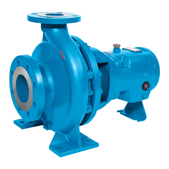
3 Product Description 3 Product Description 3.1 General description The model IC is a single-stage volute casing pump. Hydraulic design and dimensions comply with ISO 2858/ EN 22858. The technical design complies with ISO 5199/EN 25199.The model ICI addi- tionally has an inducer. Models ICH and ICIH additionally have cooling or heating of the casing cover and/or the volute casing. -
Page 19: Nameplate Information
3.2 Nameplate information Frame adapter • Provides safe and accurate alignment for the liquid end to the bearing frame. • Large access windows make installation and maintenance of seal and auxiliary support sys- tems trouble-free. Bearings Heavy-duty ball bearings provide L10 bearing life in excess of 17,500 hours. The size of the bearing frame is shown in the data sheet and/or order confirmation. - Page 20 3.2 Nameplate information Nameplate Field Explanation HYDRO PRESS Pump Test Pressure in kPag FLOW Rated pump flow in cubic metres per hour Rated pump speed in revolutions per minute MAX DESIGN WORKING PRESS Maximum Design pressure in kPag at rated temperature in de- grees Centigrade HEAD Rated pump head in metres...
-
Page 21: Installation
Electrical connections must be made by certified electricians in compliance with all in- ternational, national, state and local regulations. • Supervision by an authorized ITT representative is recommended to ensure proper in- stallation. Improper installation may result in equipment damage or decreased per- formance. -
Page 22: Foundation Requirements
4.1 Pre-installation Guideline Explanation/comment Do not install and operate the equipment in Acceptable devices: closed systems unless the system is constructed • Pressure relief valves with properly-sized safety devices and control • Compression tanks devices. • Pressure controls • Temperature controls •... -
Page 23: Baseplate-Mounting Procedures
4.2 Baseplate-mounting procedures J-type bolts Item Description Baseplate Shims or wedges Foundation Bolt Figure 5: J-type bolts 4.2 Baseplate-mounting procedures 4.2.1 Prepare the baseplate for mounting Remove all the attached equipment from the baseplate. Clean the underside of the baseplate completely. If applicable, coat the underside of the baseplate with an epoxy primer. -
Page 24: Install The Baseplate Using Jackscrews
4.2 Baseplate-mounting procedures • Two machinist's levels • Baseplate-leveling worksheet This procedure is applicable to cast iron and fabricated steel baseplates. If you use sleeve-type bolts, fill the bolt sleeves with packing material or rags to prevent grout from entering the bolt holes. Put the sets of wedges or shims on each side of each foundation bolt. - Page 25 4.2 Baseplate-mounting procedures Apply an anti-seize compound on the jackscrews. The compound makes it easier to remove the screws after you grout. Lower the baseplate carefully onto the foundation bolts and perform these steps: Cut the plates from the bar stock and chamfer the edges of the plates in order to reduce stress concentrations.
- Page 26 4.2 Baseplate-mounting procedures Item Description Machinist's levels Driver's mounting pads Foundation bolts Jackscrews Grout hole Pump's mounting pads Figure 9: Level driver mounting pads Turn the center jackscrews down so that they rest on their plates on the foundation surface. Level the pump mounting pads: NOTICE: Remove all dirt from the mounting pads in order to ensure that the correct leveling is ach-...
-
Page 27: Install The Baseplate Using Spring Mounting
4.2 Baseplate-mounting procedures 4.2.5 Install the baseplate using spring mounting NOTICE: The spring-mounted baseplate is designed only to support piping loads from thermal ex- pansion. Ensure that the suction and discharge piping are supported individually. Failure to do so may result in equipment damage. The foundation pads are not provided with the baseplate. -
Page 28: Install The Baseplate Using Stilt Mounting
4.2 Baseplate-mounting procedures Upper jam nut Follower Washer Foundation pads Spring Upper adjusting nut Spring stud Figure 11: Example of an installed spring assembly 4.2.6 Install the baseplate using stilt mounting NOTICE: The stilt-mounted baseplate is not designed to support static piping loads. Ensure that the suction and discharge piping are supported individually. - Page 29 4.2 Baseplate-mounting procedures Adjust the height and level the baseplate by moving the lower adjusting nuts. When the baseplate is level, tighten the top adjusting nuts. Fasten the lower and upper jam nuts on each stilt. Mounting plate Mounting nut Stilt bolt Foundation cups Washer...
-
Page 30: Baseplate-Leveling Worksheet
4.3 Install the pump, driver, and coupling 4.2.7 Baseplate-leveling worksheet Level measurements 1)____________________ 2)____________________ 3)____________________ 4)____________________ 5)____________________ 6)____________________ 7)____________________ 8)____________________ 9)____________________ 10)___________________ 11)___________________ 12)___________________ 13)___________________ 14)___________________ 15)___________________ 16)___________________ 17)___________________ 18)___________________ 4.3 Install the pump, driver, and coupling Mount and fasten the pump on the baseplate. Use applicable bolts. Model IC, ICI, ICH, ICIH Installation, Operation, and Maintenance Manual... -
Page 31: Pump-To-Driver Alignment
4.4 Pump-to-driver alignment Mount the driver on the baseplate. Use applicable bolts and hand tighten. Install the coupling. See the installation instructions from the coupling manufacturer. 4.4 Pump-to-driver alignment Precautions WARNING: • Misalignment can cause decreased performance, equipment damage, and even cata- strophic failure of frame-mounted units leading to serious injury. -
Page 32: Permitted Indicator Values For Alignment Checks
NOTICE: The specified permitted reading values are valid only at operating temperature. For cold settings, other values are permitted. The correct tolerances must be used. Failure to do so can result in misalignment. Contact ITT for further information. IMPORTANT •... -
Page 33: Attach The Dial Indicators For Alignment
4.4 Pump-to-driver alignment Guideline Explanation Move or shim only the driver in order to make adjustments. This prevents strain on the piping installa- tions. Make sure that the hold-down bolts for the driver are tight when This keeps the driver stationary since move- you take indicator measurements. - Page 34 4.4 Pump-to-driver alignment When the Then... reading val- ue is... Positive The coupling halves are closer at the bottom than at the top. Perform one of these steps: • Remove shims in order to lower the feet of the driver at the shaft end. •...
- Page 35 The specified permitted reading values are valid only at operating temperature. For cold settings, other values are permitted. The correct tolerances must be used. Failure to do so can result in misalignment. Contact ITT for further information. 4.4.5.4 Perform parallel alignment for a horizontal correction Refer to the alignment table in "Permitted indicator values for alignment checks"...
-
Page 36: Grout The Baseplate
The specified permitted reading values are valid only at operating temperature. For cold settings, other values are permitted. The correct tolerances must be used. Failure to do so can result in misalignment. Contact ITT for further information. 4.4.5.5 Perform complete alignment for a vertical correction A unit is in complete alignment when both the angular indicator (A) and the parallel indicator (P) do not vary by more than 0.05 mm | 0.002 in. - Page 37 4.5 Grout the baseplate Pour grout through the grout hole into the baseplate up to the level of the dam. When you pour the grout, remove air bubbles from it by using one of these methods: • Puddle with a vibrator. •...
-
Page 38: Piping Checklists
4.6 Piping checklists 4.6 Piping checklists 4.6.1 General piping checklist Precautions WARNING: • Risk of premature failure. Casing deformation can result in misalignment and contact with rotating parts, causing excess heat generation and sparks. Flange loads from the piping system, including those from the thermal expansion of the piping, must not ex- ceed the limits of the pump. -
Page 39: Permitted Nozzle Loads And Torques At The Pump Nozzles
4.6 Piping checklists Check Explanation/comment Checked Check that only necessary fittings This helps to minimize friction losses. are used. Do not connect the piping to the — pump until: • The grout for the baseplate or sub-base becomes hard. • The grout for the pit cover be- comes hard. - Page 40 4.6 Piping checklists • The values are valid for pump units with standard IC base frames (ungrouted). • All of the values refer to standard materials EN-GJS400-18LT and 1.4408. Permitted nozzle loads and torques at the pump nozzles These nozzle loads and torques follow the Europump recommendations for this pump according to ISO 5199.
- Page 41 4.6 Piping checklists Ø Forces in N | lbf Torques in Nm | ft-lb Sizes ΣF ΣM 80-50-250 80 1,750 | 393 1,580 | 1,440 | 2,760 | 1,120 | 800 | 590 910 | 671 1,650 | 1,217 80-50-315 80 1,750 | 393 1,580 | 1,440 | 2,760 | 1,120 |...
- Page 42 4.6 Piping checklists Ø Forces in N | lbf Torques in Nm | ft-lb Sizes ΣF ΣM 50-32-250 32 630 | 142 600 | 135 740 | 166 1,160 | 770 | 568 530 | 391 600 | 443 1,120 | 826 50-32-315 32 630 | 142 600 | 135 740 | 166 1,160 | 770 | 568...
-
Page 43: Suction-Piping Checklist
4.6 Piping checklists Ø Forces in N | lbf Torques in Nm | ft-lb Sizes ΣF ΣM 200-150-31 3,150 | 2,850 | 3,500 | 5,500 | 1,750 | 1,230 | 1,450 | 2,560 | 1,236 1,291 1,069 1,888 200-150-40 3,150 | 2,850 | 3,500 | 5,500 |... - Page 44 4.6 Piping checklists Check Explanation/comment Checked Assure adequate insulation is applied for To assure sufficient NPSHa. liquids with specific gravity less than 0.60. Liquid source below the pump Check Explanation/comment Checked Make sure that the suction piping is free This helps to prevent the occurrence of air and cavi- from air pockets.
-
Page 45: Discharge Piping Checklist
4.6 Piping checklists Example: Suction piping equipment Correct Incorrect Suction pipe sloping upwards from liquid Air pocket, because the eccentric reducer is source not used and because the suction piping does not slope gradually upward from the liquid Long-radius elbow source Strainer Foot valve... -
Page 46: Bypass-Piping Considerations
When to install a minimum-flow orifice You can size and install a minimum-flow orifice in a bypass line in order to prevent bypassing exces- sive flows. Consult your ITT representative for assistance in sizing a minimum-flow orifice. When a minimum-flow orifice is unavailable Consider an automatic recirculation control valve or solenoid-operated valve if a constant bypass (minimum-flow orifice) is not possible. -
Page 47: Final Piping Checklist
4.6 Piping checklists NOTICE: Auxiliary cooling and flush systems must be operating properly to prevent excess heat gen- eration, sparks, and/or premature failure. Ensure auxiliary piping is installed as specified on the pump data sheet prior to startup. When to install You may need to install auxiliary piping for bearing cooling, mechanical seal flush, or other special features supplied with the pump. -
Page 48: Commissioning, Startup, Operation, And Shutdown
5 Commissioning, Startup, Operation, and Shutdown 5 Commissioning, Startup, Operation, and Shutdown 5.1 Preparation for startup WARNING: • Risk of serious physical injury or death. Exceeding any of the pump operating limits (e.g. - pressure, temperature, power, etc.) could result in equipment failure, such as explosion, seizure, or breach of containment. -
Page 49: Remove The Coupling Guard
5.2 Remove the coupling guard NOTICE: • Verify the driver settings before you start any pump. Refer to the applicable drive equipment IOMs and operating procedures. • Excessive warm-up rates can cause equipment damage. Ensure the warm-up rate does not exceed 1.4°C | 2.5°F per minute. •... -
Page 50: Check The Rotation
5.3 Check the rotation It is not necessary to remove the end plate from the pump side of the bearing housing. You can access the bearing-housing tap bolts without removing this end plate if maintenance of internal pump parts is necessary. Remove the pump half of the coupling guard: Slightly spread the bottom apart. -
Page 51: Install The Coupling Guard
5.5 Install the coupling guard WARNING: Failure to disconnect and lock out driver power may result in serious physical injury or death. Always disconnect and lock out power to the driver before performing any installa- tion or maintenance tasks. • Electrical connections must be made by certified electricians in compliance with all in- ternational, national, state, and local rules. - Page 52 5.5 Install the coupling guard Item Description Annular groove Pump-side end plate Driver Pump half of the coupling guard Figure 21: Guard half installation The annular groove in the coupling guard half must fit around the end plate. Item Description Annular groove End plate (pump end) Guard half...
- Page 53 5.5 Install the coupling guard Item Description Washer Bolt Figure 23: Secure coupling guard half to end plate Put the driver half of the coupling guard in place: Slightly spread the bottom apart. Place the driver half of the coupling guard over the pump half of the coupling guard. The annular groove in the coupling guard half must face the motor.
-
Page 54: Bearing Lubrication
5.6 Bearing lubrication End plate Driver Figure 25: Placement of driver half of coupling guard Place the driver-side end plate in the annular groove of the driver-half of the coupling guard. Use a bolt, a nut, and two washers to secure the coupling guard half to the end plate. Hand- tighten only. -
Page 55: Lubricating Oil Requirements
Setting point (Pourpoint) -15°C | 5°F Application temperature Higher than permitted bearing temperature (Contact your ITT representative to determine a suita- ble type of lubrication if ambient temperatures are be- low -10°C | 14°F. Oil quantity requirements Bearing frame size Oil quantity in liters | quarts 0.5 | 0.53... - Page 56 5.6 Bearing lubrication 5.6.2.1 Fill the bearing frame with oil NOTICE: Maintain an exact oil level. If the oil level is too high, the bearing temperature can increase. If the oil level is too low, the bearing will not be properly lubricated and could cause opera- tional problems.
-
Page 57: Lubricating-Grease Requirements
5.7 Shaft-sealing options 5.6.3 Lubricating-grease requirements Precautions NOTICE: Avoid equipment damage or decreased performance. Never mix greases of different con- sistencies (NLGI 1 or 3 with NLGI 2) or with different thickeners. For example, never mix a lithium-based grease with a polyurea based grease. If it is necessary to change the grease type or consistency, remove the rotor and old grease from the housing before regreasing. -
Page 58: Packed Stuffing Box Option
5.7 Shaft-sealing options Seal flushing methods Table 5: You can use these methods in order to flush or cool the seal: Method Description Product flush Run the piping so that the pump pushes the pumped fluid from the casing and injects it into the seal gland. If necessary, an external heat exchanger cools the pumped fluid before it enters the seal gland. -
Page 59: Pump Priming
5.8 Pump priming 5.8 Pump priming 5.8.1 Prime the pump with the suction supply above the pump Slowly open the suction isolation valve. Open the air vents on the suction and discharge piping until the pumped fluid flows out. Close the air vents. Item Description Discharge isolation valve Check valve... - Page 60 5.8 Pump priming Item Description Discharge isolation valve Shutoff valve From outside supply Foot valve Check valve Figure 30: Pump priming with suction supply below pump with foot valve and an outside sup- Model IC, ICI, ICH, ICIH Installation, Operation, and Maintenance Manual...
-
Page 61: Other Methods Of Priming The Pump
5.9 Start the pump Item Description By-pass line Shutoff valve Foot valve Check valve Discharge isolation valve Figure 31: Pump priming with suction supply below pump with foot valve using bypass around check valve 5.8.3 Other methods of priming the pump You can also use these methods in order to prime the pump: •... -
Page 62: Limits Of Operation
5.10 Limits of operation Before you start the pump, you must perform these tasks: • Open the suction valve. • Open any recirculation or cooling lines. Fully close or partially open the discharge valve, depending on system conditions. Start the driver. Slowly open the discharge valve until the pump reaches the desired flow. -
Page 63: Pump Operation Precautions
5.11 Pump operation precautions 5.11 Pump operation precautions General considerations NOTICE: • Vary the capacity with the regulating valve in the discharge line. Never throttle the flow from the suction side. This action can result in decreased performance, unex- pected heat generation, and equipment damage. •... -
Page 64: Make The Final Alignment Of The Pump And Driver
5.13 Make the final alignment of the pump and driver 5.13 Make the final alignment of the pump and driver WARNING: • Failure to disconnect and lock out driver power may result in serious physical injury or death. Always disconnect and lock out power to the driver before performing any in- stallation or maintenance tasks. -
Page 65: Maintenance
6 Maintenance 6 Maintenance 6.1 Maintenance schedule Maintenance inspections A maintenance schedule includes these types of inspections: • Routine maintenance • Routine inspections • Three-month inspections • Annual inspections Shorten the inspection intervals appropriately if the pumped fluid is abrasive or corrosive or if the en- vironment is classified as potentially explosive. -
Page 66: Bearing Maintenance
-15°C | 5°F Application temperature Higher than permitted bearing temperature (Contact your ITT representative to determine a suita- ble type of lubrication if ambient temperatures are be- low -10°C | 14°F. Model IC, ICI, ICH, ICIH Installation, Operation, and Maintenance Manual... -
Page 67: Change The Oil
6.2 Bearing maintenance Oil quantity requirements Bearing frame size Oil quantity in liters | quarts 0.5 | 0.53 1.1 | 1.16 1.4 | 1.48 1.7 | 1.8 6.2.2 Change the oil Remove the oil drain plug (903.51). Drain the oil. Flush the pump with fresh oil. -
Page 68: Shaft Seal Maintenance
Cartridge seals installed by the user require disengagement of the holding clips prior to operation, allowing the seal to slide into place. If the seal has been installed in the pump by ITT, these clips have already been disengaged. Other mechanical seal types For other types of mechanical seals, refer to the instructions provided by the seal manufacturer for installation and setting. -
Page 69: Disassembly
6.4 Disassembly Adjustment of gland Adjust the gland if the leakage rate is greater than or less than the specified rate. Evenly adjust each of the two gland bolts with a one-quarter (1/4) turn until the desired leakage rate is obtained. Tighten the bolts to decrease the rate. Loosen the bolts to increase the rate. Tightening of packing NOTICE: Never over-tighten packing to the point where less than one drop per second is observed. -
Page 70: Tools Required
6.4 Disassembly 6.4.2 Tools required In order to disassemble the pump, you need these tools: • Bearing puller • Brass drift punch • Cleaning agents and solvents • Dial indicators • Feeler gauges • Hex wrenches • Hydraulic press • Induction heater •... - Page 71 6.4 Disassembly Oil analysis should be part of a preventive maintenance program that determines the cause of a failure. Save the oil in a clean container for inspection. The back pull out assembly consists of all parts except the casing (100). The casing (100) can remain on the foundation and in the piping, if it is not the casing itself, which must be repaired.
-
Page 72: Remove The Coupling Hub
6.4 Disassembly Mark and remove the shims from under the frame foot and save them for reassembly. 10. Remove and discard the casing gasket. You will insert a new casing gasket during reassembly. Remove the jackscrews. 12. Clean all gasket surfaces. Clean surfaces prevent the casing gasket from partially adhering to the casing due to binders and adhesives in the gasket material. -
Page 73: Remove The Seal-Chamber Cover
6.4 Disassembly 412.21 Figure 36: Impeller removal method NOTICE: • Remove shaft guard using a prying tool. • Be sure to align the pry bars with the impeller vanes in order to prevent damage to the impeller. Remove the impeller key (940.31). Place the back pull-out assembly in a vertical position before you proceed with the disassembly. -
Page 74: Remove The Stuffing-Box Cover
6.4 Disassembly NOTICE: Be careful with the mechanical seal. Carbon or ceramic components are brittle and easily broken. Remove the rotary portion of the seal from the sleeve by loosening the setscrews and sliding it off the sleeve. Refer to the mechanical-seal instructions for more information. Remove the gland (452), the stationary portion of the seal, and the O-ring (412.21). -
Page 75: Pre-Assembly Inspections
6.5 Pre-assembly inspections 320.51 932.51 302.52 923.51 Figure 40: Bearing frame cross-section Reach inside the frame and remove the snap ring (932.51) using the designated snap ring pli- ers. Use snap ring pliers according to DIN 5256-C. Refer to this table for the correct size: Bearing frame size Pliers size Minimum length of pliers 94/C 40 200 mm | 8 in. -
Page 76: Replacement Guidelines
Replace the impeller and the wear ring. • Contact your ITT representative in order to acquire a customized wear ring (bored to fit) in order to avoid replacement of the impeller. Model IC, ICI, ICH, ICIH Installation, Operation, and Maintenance Manual... - Page 77 When the volute casing (102V) or casing cover (161) without a wear ring must be repaired, you can install a wear ring in order to renew pump performance. The volute casing and/or the cas- ing cover must be re-machined. Contact your ITT representative for assistance. 102V 502.11...
-
Page 78: Shaft And Sleeve Replacement Guidelines
6.5 Pre-assembly inspections • Make sure the O-ring surface is clean. Oil seal replacement Replace the oil seal if it has cuts or cracks. Gaskets, O-rings, and seats replacement WARNING: Risk of death or serious injury. Leaking fluid can cause fire and/or burns. Replace all gas- kets and O-rings at each overhaul or disassembly. -
Page 79: Seal Chamber And Stuffing Box Cover Inspection
6.5 Pre-assembly inspections • Make sure that all lubrication passages are clear. • If the frame has been exposed to pumped fluid, inspect the frame for corrosion or pitting. • Inspect the inboard-bearing bores. Surface inspection locations This figure shows the areas to inspect for wear on the bearing frame inside and outside surface. Figure 47: Inside and outside inspection locations 6.5.4 Seal chamber and stuffing box cover inspection Checklist... -
Page 80: Bearings Inspection
6.6 Reassembly Figure 48: Seal chamber Figure 49: Stuffing box cover 6.5.5 Bearings inspection Condition of bearings Do not reuse bearings. The condition of the bearings provides useful information on operating condi- tions in the bearing frame. Checklist Perform these checks when you inspect the bearings: •... - Page 81 6.6 Reassembly NOTICE: • Ensure that the pipe threads are clean. Apply thread sealant to the plugs and fittings. Failure to do so may result in oil leaks and equipment damage. • There are several methods you can use to install bearings. The recommended meth- od is to use an induction heater that heats and demagnetizes the bearings.
- Page 82 6.6 Reassembly Figure 52: Snap ring detail As a recommendation, thread a stud into one of the four threaded bolt holes in the frame adapter (344), and finger tighten only. The stud must be between 40 and 50 mm in length. This helps you to align the adapter bolt holes to the frame bolt holes during assembly.
-
Page 83: Install The Impeller
6.6 Reassembly 6.6.2 Install the impeller CAUTION: Risk of physical injury from sharp edges. Wear heavy work gloves when handling impellers. For the fitting threads and for tight tolerances, use a suitable anti-seize compound. Use this, for ex- ample, between the shaft sleeve and the shaftmotor shaft and pump shaft or between the impeller and the shaft. - Page 84 6.6 Reassembly NOTICE: The mechanical seal must have an appropriate seal-flush system. Failure to do so will result in excess heat generation and seal failure. 6.6.3.1 Seal the shaft with a packed stuffing box WARNING: Packed stuffing boxes are not allowed in an ATEX-classified environment. WARNING: Failure to disconnect and lock out driver power may result in serious physical injury.
- Page 85 6.6 Reassembly CAUTION: Running a mechanical seal dry, even for a few seconds, can cause seal failure and physi- cal injury. Never operate the pump without liquid supplied to the mechanical seal. Slide the cartridge seal onto the shaft or sleeve until it contacts the inboard labyrinth oil seal. Assemble the seal chamber.
-
Page 86: Install The Back Pull-Out Assembly
6.6 Reassembly 6.6.4 Install the back pull-out assembly WARNING: Lifting and handling heavy equipment poses a crush hazard. Use caution during lifting and handling and wear appropriate Personal Protective Equipment (PPE, such as steel-toed shoes, gloves, etc.) at all times. Seek assistance if necessary. Clean the casing fit and install the casing gasket (400) on the seal chamber and stuffing-box cover. -
Page 87: Assembly References
6.6 Reassembly 6.6.6 Assembly references 6.6.6.1 Sound pressure levels Sound pressure levels L in dB(A) Nominal power P Pump Pump and motor in kW 2950 min 1450 min 975 min 2950 min 1450 min 975 min 0,55 50,0 49,5 49,0 58,0 52,0 51,5... - Page 88 6.6 Reassembly Location Bolt size Torque for lubricated threads in Nm | lb-ft Torque for dry threads in Nm | lb-ft 150 | 111 220 | 162 Nut torque values This table provides the recommended nut torque values. Location Frame size Torque for lubricated threads in Nm | lb-ft Torque for dry threads in Nm | lb-ft 35 | 26 45 | 33 105 | 77...
- Page 89 6.6 Reassembly Component Number of Pumps (includes stand-by pumps) Number of Spare Parts Shaft with key and 20% (see calculation nuts note) Ball bearing set 25% (see calculation note) Shaft sleeve 50% (see calculation note) Lantern ring 30% (see calculation note) Packing ring 100% (see calculation...
-
Page 90: Troubleshooting
The foot valve or suction pipe Consult an ITT representative opening is not submerged for the proper submersion depth. enough. Use a baffle in order to eliminate vortices. -
Page 91: Alignment Troubleshooting
If this does not help, then contact your ITT rep- resentative. The liquid is heavier than ex- Check the specific gravity and pected. -
Page 92: Assembly Troubleshooting
7.3 Assembly troubleshooting 7.3 Assembly troubleshooting Symptom Cause Remedy There is excessive shaft end play. The internal clearance of the bearings Replace the bearings with a exceeds the recommended amount. bearing of the correct type. The snap ring is loose in the bearing- Re-seat the snap ring. -
Page 93: Parts Listings And Cross-Sectionals
8 Parts Listings and Cross-Sectionals 8 Parts Listings and Cross-Sectionals 8.1 Parts list Cross-sectional drawing Parts list and materials of construction Pump material Item Part name Ductile 316 SS Duplex Alloy 20 Hastelloy Titanium iron (NL) (VV) (WW) (AA) (BB/CC) (TT) 102V Casing... - Page 94 8.1 Parts list Pump material Item Part name Ductile 316 SS Duplex Alloy 20 Hastelloy Titanium iron (NL) (VV) (WW) (AA) (BB/CC) (TT) 940.31 Impeller key Carbon steel Parts not shown Pump material Item Part name Ductile 316 SS Duplex Alloy 20 Hastelloy Titanium...
-
Page 95: Other Relevant Documentation Or Manuals
9 Other Relevant Documentation or Manuals 9 Other Relevant Documentation or Manuals 9.1 For additional documentation For any other relevant documentation or manuals, contact your ITT representative. Model IC, ICI, ICH, ICIH Installation, Operation, and Maintenance Manual... -
Page 96: Local Itt Contacts
Los Angeles Vertical Products Operation +1 562-949-2113 +1 562-695-8523 3951 Capitol Avenue City of Industry, CA 90601-1734 Asia Pacific ITT Fluid Technology Asia Pte +65 627-63693 +65 627-63685 1 Jalan Kilang Timor #04-06 Singapore 159303 Europe ITT - Goulds Pumps... - Page 97 Visit our website for the latest version of this document and more information: http://www.gouldspumps.com Goulds Pumps 240 Fall Street Seneca Falls, NY 13148 Form en-US.2010-07.IOM.IC/ICI/ICH/ICIH ©2010 ITT Corporation The original instruction is in English. All non-English instructions are translations of the original instruction.
Need help?
Do you have a question about the Goulds Pumps IC and is the answer not in the manual?
Questions and answers