Table of Contents
Advertisement
Quick Links
Advertisement
Table of Contents

Subscribe to Our Youtube Channel
Related Manuals for ITT Goulds Pumps VIS


Summary of Contents for ITT Goulds Pumps VIS
- Page 1 Installation, Operation and Maintenance Instructions...
-
Page 3: Table Of Contents
Table of Contents Table of Contents 1 Safety.................................. 3 1.1 Important Safety Notice..........................3 1.2 Safety warnings............................3 1.3 Safety ................................ 4 1.4 General precautions ..........................5 1.5 ATEX Considerations and Intended Use....................8 1.6 Parts ................................9 2 Introduction..............................10 2.1 Introduction.............................. - Page 4 Table of Contents 7.9 Turbine Bowl With Taper Collet-Reassembly ..................28 8 Parts List ................................. 29 8.1 General..............................29 8.2 Ordering Parts ............................29 8.3 Return Parts ............................29 VIS Installation, Operation and Maintenance Instructions...
-
Page 5: Safety
ITT Goulds pumps will provide safe, trouble-free service when properly installed, maintained, and operat- Safe installation, operation, and maintenance of ITT Goulds Pumps equipment are an essential end user responsibility. This Pump Safety Manual identifies specific safety risks that must be considered at all times during product life. -
Page 6: Safety
Trapped liquid can rapidly expand and result in a violent explosion and injury. ITT Goulds Pumps will not accept responsibility for physical injury, damage, or delays caused by a failure to observe the instructions for installation, operation, and maintenance contained in this Pump Safety Manual or the current IOM available at http://www.gouldspumps.com/literature. -
Page 7: General Precautions
Personal injuries will result if procedures outlined in this manual are not followed. ITT Goulds Pumps will not accept responsibility for physical injury, damage or delays caused by a failure to observe the instructions in this manual and the IOM provided with your equip- ment. - Page 8 Lift equipment only at specifically identified lifting points or as instructed in the current IOM. Current manuals are available at www.gouldspumps.com/literature_ioms.html or from your local ITT Goulds Pumps sales representative. Note: Lifting devices (eyebolts, slings, spreaders, etc.) must be rated, selected, and used for the entire load being lifted.
- Page 9 1.4 General precautions WARNING Make sure to properly lubricate the bearings. Failure to do so may result in ex- cess heat generation, sparks, and / or premature failure. CAUTION The mechanical seal used in an ATEX classified environment must be proper- ly certified.
-
Page 10: Atex Considerations And Intended Use
Maintenance manual (IOM) can cause serious personal injury or damage to the equipment. This in- cludes any modification to the equipment or use of parts not provided by ITT Goulds Pumps. If there is any question regarding the intended use of the equipment, please contact an ITT Goulds representative before proceeding. -
Page 11: Parts
The code classification marked on the equipment must be in accordance with the specified area where the equipment will be installed. If it is not, do not operate the equipment and contact your ITT Goulds Pumps sales representative before proceeding. -
Page 12: Introduction
2 Introduction 2 Introduction 2.1 Introduction The design, material, and workmanship incorporated in the construction of Goulds pumps makes them capable of giving long, trouble-free service. The life and satisfactory service of any mechanical unit, how- ever, is enhanced and extended by correct application, proper installation, periodic inspection, and care- ful maintenance. - Page 13 Materials and Equipment Required Clamp-on ammeter Voltmeter A good grade of pipe joint compound should be available to facilitate assembly and possible fu- ture disassembly. Installation equipment Although portable derricks are sometime used, a properly designed pump setting rig is recom- mended.
-
Page 14: Storage
3 Storage 3 Storage 3.1 Storage Goulds Pumps carefully preserves and protects its products for shipment. However, the effective life of the preservatives applied at the factory can vary from 3 to 18 months depending on the severity of the environment in which the equipment is stored. -
Page 15: General Description
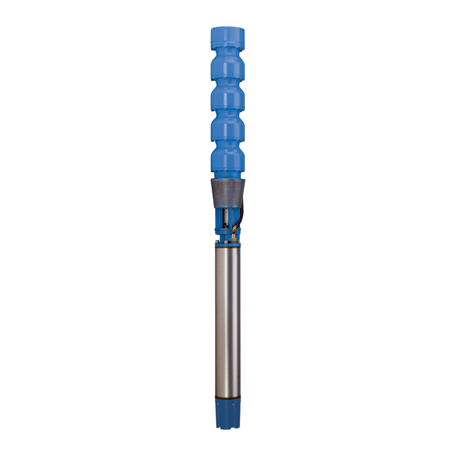
4 General Description 4 General Description 4.1 General Description Goulds' model VIS pump is a submersible turbine pump designed for maximum dependability. The VIS pump also features capacities from 100 to 6000 GPM and larger, heads to 1400 feet. See image below for typical VIS pump. - Page 16 4.1 General Description Discharge Suction Figure 2: Pump cross-section with call-outs Submersible motor, HP-PH-CY-V RPM-frame Part No. Description Coupling Pump shaft Coupling Bowl Intmd VIS Installation, Operation and Maintenance Instructions...
- Page 17 4.1 General Description Part No. Description Adapter SBM Bearing Intmd Impeller Taper lock Wearing ring-bowl Bearing, suction/discharge Sand collar Screen suction VIS Installation, Operation and Maintenance Instructions...
-
Page 18: Pump Installation
5 Pump Installation 5 Pump Installation 5.1 Pump Installation NOTICE: Pump Installation: All bolts are torqued by the factory and secured with Loctite. It is recognized that transportation and handling may result in bolt relaxation, therefore, check that all fasteners on the pump are tight prior to installation. -
Page 19: Preparation For Installation
5.3 Preparation for Installation be constructed of solid concrete, how ever, adequate beams or timbers may be used. A common founda- tion consists of the following concrete mixture: One part cement Two parts sand Four parts gravel with sufficient water to make a stiff mix 5.3 Preparation for Installation •... -
Page 20: Energizing The Motor
5.5 Energizing the Motor Cut off the motor leads to equal length. Clean off the ends of the leads for about a foot, using a cloth wet with gasoline or solvent. Clean the end of the power cable also. Insert the three motor leads into the corresponding holes in the bottom of the rubber casing and push them several inches out the top. -
Page 21: Lowering Pump Into Well
5.6 Lowering Pump into Well • When the rotation is correct, mark the leads. At this time, copy the full load amperes from the motor name plate. This data will be required before starting the unit for the first time after it is in the well. CAUTION: With the lifting hook in place, secure the cable above the lifting hook to avoid tension on the motor leads and splice. -
Page 22: Electrical Cable
5.9 Electrical Cable motor. In addition, the maximum variation of any phase from the average value should not exceed one percent. The effect of unbalanced supply voltage is to create a current unbalance and increased losses in the motor far out of proportion to the magnitude of the voltage imbalance. 5.9 Electrical Cable It is also important that the cable be tested both before and during the installation. - Page 23 5.11 Airline Installation and Operation generally the discharge elbow base. The airline should extend past the bowls to about the middle of the motor. As the length of discharge pipe is known, the distance to the top of the bowl assembly from the foundation is usually some multiple of 10 feet.
-
Page 24: General
6 General 6 General 6.1 Operation at Shutoff Heads In the usual application of vertical turbine pumps, no harm will result from operation under conditions of static flowheads; however, not all installations are "usual" and, for this reason, consideration should be given to any unit which may be subjected to this usage. The following points should therefore be checked and resolved before putting the equipment into operation at or near shutoff heads. -
Page 25: Pump Disassembly And Reassembly
7 Pump Disassembly and Reassembly 7 Pump Disassembly and Reassembly 7.1 Pump Disassembly NOTICE: Pump shall not be operated outside of the preferred operating range except during startup. Do not operate pump below recommended minimum flow as severe damage may occur. NOTICE: Pump components should be match marked prior to disassembly. - Page 26 7.2 Bowl Disassembly Begin disassembly by removing the capscrews that secure the discharge bowl and the first in- termediate bowl, and slide off pump shaft. Remove sand collar by heating. (Not the shaft.) Pull shaft out as far as possible and strike impeller hub utilizing a collet driver or equivalent slid- ing along the pumpshaft to drive the impeller off the taper collet.
- Page 27 7.2 Bowl Disassembly Figure 4: Figure 5: After impeller is freed, insert a screwdriver into the taper collet to spread it. Slide taper collet and impeller off the pumpshaft. VIS Installation, Operation and Maintenance Instructions...
- Page 28 7.2 Bowl Disassembly Figure 6: Use the preceding procedures until entire turbine bowl assembly is completely disassembled. Figure 7: VIS Installation, Operation and Maintenance Instructions...
-
Page 29: Turbine Bowl-Wear Rings Removal
7.3 Turbine Bowl-Wear Rings Removal 7.3 Turbine Bowl-Wear Rings Removal Utilizing a diamond point chisel, cut two "V" shape grooves on the bowl wear ring approximately 180 degrees apart. Use extreme care not to damage the wear ring seat. Figure 8: Cut "V" shape grooves on bowl wear ring With a chisel or equal, knock the end of one half of the ring in, and pry ring out. -
Page 30: Turbine Bowl-Impeller Wear Ring Removal
7.4 Turbine Bowl-Impeller Wear Ring Removal 7.4 Turbine Bowl-Impeller Wear Ring Removal Set up impeller in a lathe and machine wear ring off, use extreme care not to machine or damage ring seat or impeller hub. Impeller wear ring may also be removed by following steps in 7.3 Turbine Bowl-Wear Rings Removal on page 7.5 Bowl, Suction Bell, and Discharge Bowl Bearing Removal... - Page 31 8 Parts List 8 Parts List 8.1 General The requirement for a stock of spare parts shall vary with the severity of conditions of service, and the extent of field maintenance anticipated, and the number of pumps installed. A minimum of one spare of each rotating part should be stocked, as well as a complete set of bearings and seals.
- Page 32 Visit our website for the latest version of this document and more information: www.gouldspumps.com 3951 Capitol Avenue City of Industry, CA 90601-1734 Form IOM.VIS.en-US.2021-06 ©2021 ITT Corporation The original instruction is in English. All non-English instructions are translations of the original instruction.
Need help?
Do you have a question about the Goulds Pumps VIS and is the answer not in the manual?
Questions and answers