Table of Contents
Advertisement
Quick Links
Advertisement
Table of Contents

Related Manuals for ITT Goulds Pumps ICP


Summary of Contents for ITT Goulds Pumps ICP
- Page 1 Installation, Operation and Maintenance Instruction Model ICP, ICPI, ICPH, ICPIH...
-
Page 3: Table Of Contents
Table of Contents Table of Contents 1 Introduction and Safety ............................ 3 1.1 Important Safety Notice..........................3 1.2 Safety warnings............................3 1.3 Safety ................................ 4 1.4 General precautions ..........................5 1.5 ATEX Considerations and Intended Use....................7 1.6 Parts ................................9 2 Transportation and Storage.......................... - Page 4 Table of Contents 6 Maintenance..............................31 6.1 Maintenance schedule ..........................31 6.2 Mechanical seals............................. 32 6.3 Stuffing boxes............................32 6.4 Lubrication and Change of Lubricant ...................... 32 6.5 Coupling ..............................33 6.6 Cleaning of pump ............................ 34 6.7 Disassembly precautions ........................34 6.8 General remarks............................
-
Page 5: Introduction And Safety
ITT Goulds pumps will provide safe, trouble-free service when properly installed, maintained, and operat- Safe installation, operation, and maintenance of ITT Goulds Pumps equipment are an essential end user responsibility. This Pump Safety Manual identifies specific safety risks that must be considered at all times during product life. -
Page 6: Safety
Trapped liquid can rapidly expand and result in a violent explosion and injury. ITT Goulds Pumps will not accept responsibility for physical injury, damage, or delays caused by a failure to observe the instructions for installation, operation, and maintenance contained in this Pump Safety Manual or the current IOM available at www.gouldspumps.com/literature. -
Page 7: General Precautions
Personal injuries will result if procedures outlined in this manual are not followed. ITT Goulds Pumps will not accept responsibility for physical injury, damage or delays caused by a failure to observe the instructions in this manual and the IOM provided with your equip- ment. - Page 8 1.4 General precautions WARNING Alignment: Shaft alignment procedures must be followed to prevent catastrophic failure of drive components or unintended contact of rotating parts. Follow coupling manufacturer's coupling installation and operation procedures. WARNING Before beginning any alignment procedure, make sure driver power is locked out. Fail- ure to lock out driver power will result in serious physical injury.
-
Page 9: Atex Considerations And Intended Use
1.5 ATEX Considerations and Intended Use CAUTION Never operate the pump without liquid supplied to mechanical seal. Running a mechani- cal seal dry, even for a few seconds, can cause seal damage and must be avoided. Physical injury can occur if mechanical seal fails. WARNING Never attempt to replace packing until the driver is properly locked out and the coupling spacer is removed. - Page 10 1.5 ATEX Considerations and Intended Use includes any modification to the equipment or use of parts not provided by ITT Goulds Pumps. If there is any question regarding the intended use of the equipment, please contact an ITT Goulds representative before proceeding.
-
Page 11: Parts
The code classification marked on the equipment must be in accordance with the specified area where the equipment will be installed. If it is not, do not operate the equipment and contact your ITT Goulds Pumps sales representative before proceeding. -
Page 12: Transportation And Storage
2 Transportation and Storage 2 Transportation and Storage 2.1 Inspect the delivery 2.1.1 Inspect the package Inspect the package for damaged or missing items upon delivery. Note any damaged or missing items on the receipt and freight bill. File a claim with the shipping company if anything is out of order. If the product has been picked up at a distributor, make a claim directly to the distributor. -
Page 13: Storage Guidelines
2.3 Storage guidelines CAUTION: Risk of injury or equipment damage from use of inadequate lifting devices. Ensure lifting devi- ces (such as chains, straps, forklifts, cranes, etc.) are rated to sufficient capacity. Precautions for lifting the pump WARNING: • Dropping, rolling or tipping units, or applying other shock loads, can cause property dam- age and/or personal injury. -
Page 14: Frostproofing
2.3 Storage guidelines Storage requirements depend on the amount of time that you store the unit. The normal packaging is designed only to protect the unit during shipping. Length of time in storage Storage requirements Upon receipt/short-term (less than six •... -
Page 15: Product Description
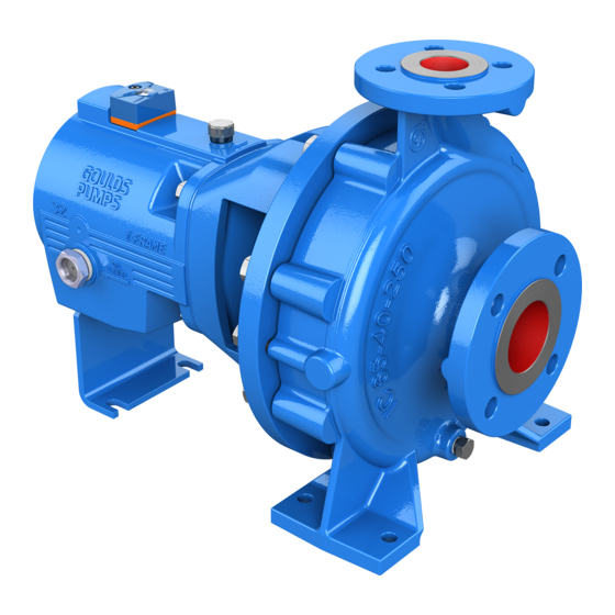
3 Product Description 3 Product Description 3.1 General description ICP pumps are single-stage volute casing pumps in process design. Hydraulic design and dimensions comply with ISO 2858/ EN 22858, the technical design complies with ISO 5199/EN 25199. For pump pressure up to 25 bar and volute casing with center-line feet. ICPI pumps as design ICP, except that they have an inducer. -
Page 16: Nameplate Information
3.2 Nameplate information • For cooling use pure, non-aggressive water with a maximum incoming temperature of 30°C |86°F . • Cooling water should be hand-warm at discharge. • The pressure in the cooling system must not exceed max. 6 bar | 87 PSI. •... -
Page 17: Installation
Electrical connections must be made by certified electricians in compliance with all inter- national, national, state and local regulations. • Supervision by an authorized ITT representative is recommended to ensure proper instal- lation. Improper installation may result in equipment damage or decreased performance. 4.1.1 Pump location guidelines WARNING: Safe lifting points are specifically identified in this manual. -
Page 18: Foundation Requirements
4.2 Piping checklists Guideline Explanation/comment Do not install and operate the equipment in closed Acceptable devices: systems unless the system is constructed with • Pressure relief valves properly-sized safety devices and control devices. • Compression tanks • Pressure controls • Temperature controls •... - Page 19 4.2 Piping checklists The data for forces and torques are only valid for static piping loads. All values for forces and torques refer to standard materials EN-GJS400-18LT and 1.4408. Figure 4: Permitted Nozzle loads and torques at pump Nozzle Suction nozzle Discharge nozzle ∅DN ∅DN...
-
Page 20: Final Control
4.2 Piping checklists 125-80-250 125 2210 2000 1800 3480 1180 840 1070 1710 80 1260 1150 1400 2200 900 1320 125-80-315 125 2210 2000 1800 3480 1180 840 1070 1710 80 1260 1150 1400 2200 900 1320 125-100-20 2210 2000 1800 3480 1180 840 1070 1710 100 1680 1520 1880 2950 980 1450... -
Page 21: Connection Of Piping To The Pump
4.2 Piping checklists 4.2.5 Connection of Piping to the Pump NOTICE: The pump must not be used as fixed point for the piping. The permitted piping loads must not be exceeded, refer to . Suction and discharge pipe • The pipes must be of a size and design that liquid can flow freely into the pump and that the pump functions without problems. -
Page 22: Coupling
4.2 Piping checklists • When emptying the pipe after the pressure test, make sure that the pump is treated properly (dan- ger of rust and problems when starting up). • In the case of pumps with stuffing boxes, replace packing after pressure test (packing may be over- compressed and thus no longer suitable for use). - Page 23 4.2 Piping checklists halves must have the same distance to one another on every of the circumference. This must be checked by means of a tracer, gauge or dial gage; refer to Figure 6: Alignment of coupling with gauge and ruler on page 21 Figure 7: Alignment of coupling with spacer on page •...
- Page 24 4.2 Piping checklists Coupling Guard WARNING: • Running a pump without safety devices exposes operators to risk of serious personal in- jury or death. Never operate a unit unless appropriate safety devices (guards, etc.) are properly installed. See specific information about safety devices in other sections of this manual.
- Page 25 4.2 Piping checklists Item No. Description Bearing cover Coupling Motor Screw part 2 at button of bearing cover Figure 9: Coupling guard assembly - Step 1 Item No. Description Insert part 3 with slot downwards with press axially to the motor Figure 10: Coupling guard assembly - Step 2 Model ICP, ICPI, ICPH, ICPIH Installation, Operation and Maintenance Instruction...
-
Page 26: Drive
4.3 Drive Item No. Description Screw part 1 to the bearing cover Screw part 1 and part 2 together, which fixes the adjusting piece Figure 11: Coupling guard assembly - Step 3 4.3 Drive On selecting the motor size care has to be taken, that the requirements according to ISO 5199 are fulfil- led. -
Page 27: Commissioning, Startup, Operation, And Shutdown
5 Commissioning, Startup, Operation, and Shutdown 5 Commissioning, Startup, Operation, and Shutdown 5.1 Preparation for startup WARNING: • Risk of serious physical injury or death. Exceeding any of the pump operating limits (e.g. - pressure, temperature, power, etc.) could result in equipment failure, such as explosion, seizure, or breach of containment. -
Page 28: Start The Pump
5.2 Start the pump NOTICE: • Verify the driver settings before you start any pump. Refer to the applicable drive equip- ment IOMs and operating procedures. • The mechanical seal used in an Ex-classified environment must be properly certified. NOTICE: You must follow these precautions before you start the pump: •... -
Page 29: Switch On Drive
5.4 Switch on drive 5.4 Switch on drive Immediately (max. 10 seconds on 50 Hz resp. max. 7 seconds on 60 Hz currency feed) after reach- ing normal operating speed open discharge valve adjust the required operating point. The pumping data shown at the type plate resp. -
Page 30: Limits Of Operation
5.6 Limits of operation 5.6 Limits of operation Flow limits WARNING: Risk of serious physical injury or death. Exceeding any of the pump operating limits (e.g. - pressure, temperature, power, etc.) could result in equipment failure, such as explosion, seiz- ure, or breach of containment. -
Page 31: Abrasive Media
5.8 Abrasive Media • Risk of equipment damage and serious physical injury. Heat build-up can cause rotating parts to score or seize. Observe pump for excessive heat build-up. If normal levels are exceeded, shut down and resolve. NOTICE: Cavitation can cause damage to the internal surfaces of the pump. Ensure net positive suction head available (NPSH ) always exceeds NPSH required (NPSH ) as shown on the published... -
Page 32: Shut Down
5.10 Shut down • Make sure that o-ring is on reservoir spout. • Place thumb over reservoir spout, invert, and insert the spout into the internal threaded boss on the main body. Tighten reservoir. • Now the oil is flowing from the reservoir into the bearing chamber. •... -
Page 33: Maintenance
6 Maintenance 6 Maintenance 6.1 Maintenance schedule Maintenance inspections A maintenance schedule includes these types of inspections: • Routine maintenance • Routine inspections • Three-month inspections • Annual inspections Shorten the inspection intervals appropriately if the pumped fluid is abrasive or corrosive or if the envi- ronment is classified as potentially explosive. -
Page 34: Mechanical Seals
6.2 Mechanical seals 6.2 Mechanical seals NOTICE: Before opening the pump, it is essential that you note Safety Regulations and Dismantling and repair of pump. If the liquid being handled leaks out at the mechanical seal, it is damaged and must be replaced. Replacement of the mechanical seal according to accompanying "Mounting Instructions for Shaft seal- ing". -
Page 35: Coupling
6.5 Coupling Kinematic viscosity at 40°C | 104°F 46 ±4 mm2/s Flash point (acc. to Cleveland) +175°C | +347°F Setting point (Pourpoint) -15°C | 5°F Application temperature * higher than permitted bearing tempera- ture * For ambient temperatures under -10°C | 14°F another suitable type of lubrication oil must be used. Request required. -
Page 36: Cleaning Of Pump
6.6 Cleaning of pump Size ΔS [mm] NOTICE: If wear is heavy, it must be assumed that the motor is not properly aligned with the pump or that the distance between the coupling sections has changed. Replace worn elements and re- install or adjust coupling, as described in 4.2.6 Coupling on page 6.6 Cleaning of pump... -
Page 37: General Remarks
6.8 General remarks • Risk of serious personal injury from exposure to hazardous or toxic liquids. A small amount of liquid will be present in certain areas like the seal chamber upon disassembly. CAUTION: • Avoid injury. Worn pump components can have sharp edges. Wear appropriate gloves while handling these parts. -
Page 38: Removal Of The Back Pull Out Assembly
6.10 Removal of the Back Pull Out Assembly You will only need common tools. Before disassembly check if required parts are ready. Disassemble the pump only so far, as required for the replacement of the repair part. 6.10 Removal of the Back Pull Out Assembly The back pull out assembly consists of all pump parts except the volute casing (102V). - Page 39 6.11 Removal of Impeller For further dismounting, and for installation, the Back Pull Out Assembly should be placed in a vertical position. Prevent assembly from tipping! Loosen impeller nut (922) (right threaded) by fixing the rotor at the coupling end. Draw off the impeller (230) with two screw drivers or pry bars.
-
Page 40: Remove The Shaft Sealing
6.12 Remove the Shaft Sealing 6.12 Remove the Shaft Sealing Before you remove casing cover refer to Mounting Instructions for Shaft Sealing. Unfasten hexagonal nut (902.32) (not available on all pump sizes) and take casing cover (161) out of bearing bracket (344). 6.13 Removal of Bearing Remove coupling with a coupling puller (Figure 18: Coupling puller on page... -
Page 41: Preassembly Inspections
6.14 Preassembly inspections Remove the anti-friction bearing (320.51 and 320.52) from the shaft (210) using a hydraulic press or a bearing puller. 6.14 Preassembly inspections 6.14.1 Reconditioning After disassembly all parts must be cleaned and checked for wear carefully. Worn or damaged parts must be replaced by new parts (spare parts). -
Page 42: Reassembly
6.15 Reassembly clearance a worn max. 1,7 (mm) When the wear limits has been reached or exceeded, the worn parts must be replaced. For volute casings (102V) with a wear ring (502.11) and cover casings (161) with a wear ring (502.31) there are the following possibilities to restore the correct clearance: Renew impeller (230) and wear ring. - Page 43 6.15 Reassembly Push the flinger (507) onto the shaft (210) till it rests axially against the shoulder of the shaft. Be- tween flinger (507) and Bearing bracket lantern (344) there must remain a clearance of at least 0.7 mm | 0.03 in. If necessary you can use a driver for mounting.
-
Page 44: Recommended Spare Parts, Spare Pumps
7 Recommended Spare Parts, Spare Pumps 7 Recommended Spare Parts, Spare Pumps 7.1 Spare Parts Number of pumps (including stand-by pumps) 8/9 10/+ Spare Parts Number of Spare Parts Impeller Wear ring Shaft with key and nuts Ball Bearing Shaft sleeve Lantern ring Packing ring Joints for pump cas-... -
Page 45: Stand-By Pumps
7.3 Stand-by pumps NOTICE: Store spare parts in dry and clean rooms. 7.3 Stand-by pumps NOTICE: It is essential that a sufficient number of stand-by pumps are kept ready for use in plants where failure of a pump could endanger human life or cause damage to property or high costs. Regu- lar checks should be carried out to ensure that such pumps are always ready for use (see Stor- age / longer periods of non-operation). -
Page 46: Troubleshooting
8 Troubleshooting 8 Troubleshooting 8.1 Operation troubleshooting The following notes on causes of faults and how to repair them are intended as an aid to recognising the problem. The manufacturer's Customer Service Department is available to help repair faults that the op- erator cannot or does not want to repair. - Page 47 8.1 Operation troubleshooting Symptom Cause Remedy Density and/or viscosity of liquid han- Seek assistance dled is too high Discharge stops after a time Flow too little Increase min. flow (open discharge valve, bypass) Pump or suction/intake pipe blocked Clean Suction height too big / NPSH of sys- •...
- Page 48 8.1 Operation troubleshooting Symptom Cause Remedy Density and/or viscosity of liquid han- Seek assistance dled is too high Head too high Speed too high • Reduce speed • Compare speed of motor with specified pump speed (rating plate) • When adjusting speed (frequen- cy transformer) check reference value setting Impeller diameter too big...
- Page 49 8.1 Operation troubleshooting Symptom Cause Remedy Bearing damaged Replace Check lubricant and bearing space for pollutants (rinse oil area) System-related vibrations (resonance) Seek assistance Temperature in pump too high Flow too little Increase min. flow (open discharge valve, bypass) Pump and/or pipes not completely fil- •...
- Page 50 8.1 Operation troubleshooting Symptom Cause Remedy Pump leaking Forces in pipeline too high (pump unit • Change (support pipes, use under strain) compensator’s, etc.) • Is foundation plate/frame proper- ly cast in place? Sealing insufficient • Tighten screws • Replace sealing Leakage rate at shaft sealing too Stuffing box not straight Tighten evenly...
- Page 51 Visit our website for the latest version of this document and more information: www.gouldspumps.com ITT - Goulds Pumps 240 Fall Street Senenca Falls, NY 13148 Form IOM.ICP.en-US.2020-02 ©2020 ITT Corporation The original instruction is in English. All non-English instructions are translations of the original instruction.
Need help?
Do you have a question about the Goulds Pumps ICP and is the answer not in the manual?
Questions and answers