Table of Contents
Advertisement
Quick Links
Advertisement
Table of Contents

Related Manuals for ITT Goulds Pumps Trash Hog II


Summary of Contents for ITT Goulds Pumps Trash Hog II
- Page 1 Installation, Operation, and Maintenance Manual Model Trash Hog II...
-
Page 3: Table Of Contents
Table of Contents Table of Contents 1 Introduction and Safety ............................ 3 1.1 Introduction..............................3 1.1.1 Requesting other information ......................3 1.1.2 Safety .............................. 3 1.1.3 Product warranty ..........................8 2 Transportation and Storage..........................9 2.1 Inspect the delivery ........................... 9 2.1.1 Inspect the package ........................ - Page 4 Table of Contents 6.5.4 Disassembly..........................39 6.6 Preassembly inspections......................... 40 6.6.1 Replacement guidelines........................ 40 6.6.2 Bearing-frame inspection ......................41 6.7 Reassembly............................. 41 6.7.1 Reassembly ..........................41 6.8 Impeller Nut Installation Torque....................... 41 6.9 Winter Storage ............................41 7 Troubleshooting .............................. 43 7.1 Troubleshooting Guide ..........................
-
Page 5: Introduction And Safety
For instructions, situations, or events that are not consid- ered in this manual or in the sales documents, please contact the nearest ITT representative. Always specify the exact product type and serial number when requesting technical information or spare parts. - Page 6 Risk of injury and/or property damage. Operating a pump in an inappropriate application can cause over pressurization, overheating, and/or unstable operation. Do not change the service application without the approval of an authorized ITT representative. 1.1.2.1 Safety terminology and symbols...
- Page 7 WARNING: If the product has been contaminated in any way, such as from toxic chemicals or nuclear radi- ation, do NOT send the product to ITT until it has been properly decontaminated and advise ITT of these conditions before returning.
- Page 8 1.1 Introduction • Avoid all electrical dangers. Pay attention to the risks of electric shock or arc flash hazards. • Always bear in mind the risk of drowning, electrical accidents, and burn injuries. Safety equipment Use safety equipment according to the company regulations. Use this safety equipment within the work area: •...
- Page 9 1.1 Introduction • Make sure that the product cannot roll or fall over and injure people or damage property. • Make sure that the lifting equipment is in good condition. • Use a lifting harness, a safety line, and a breathing device as required. •...
-
Page 10: Product Warranty
All service and repair work is done by ITT-authorized personnel. • Genuine ITT parts are used. • Only Ex-approved spare parts and accessories authorized by ITT are used in Ex-approved prod- ucts. Limitations The warranty does not cover faults caused by these situations: •... -
Page 11: Transportation And Storage
2 Transportation and Storage 2 Transportation and Storage 2.1 Inspect the delivery 2.1.1 Inspect the package Inspect the package for damaged or missing items upon delivery. Note any damaged or missing items on the receipt and freight bill. File a claim with the shipping company if anything is out of order. If the product has been picked up at a distributor, make a claim directly to the distributor. - Page 12 2.2 Transportation guidelines • Safe lifting points are specifically identified in this manual. It is critical to lift the equipment only at these points. Integral lifting eyes or eye bolts on pump and motor components are intended for use in lifting the individual components only. •...
-
Page 13: Storage Guidelines
2.3 Storage guidelines Figure 2: Example of a proper lifting method 2.3 Storage guidelines 2.3.1 Storage location The product must be stored in a covered and dry location free from heat, dirt, and vibrations. NOTICE: • Protect the product against humidity, heat sources, and mechanical damage. •... -
Page 14: Frostproofing
2.3 Storage guidelines Length of time in storage Storage requirements Upon receipt/short-term (less than six months) • Store in a covered and dry location. Long-term (more than six months) • Store in a covered and dry location. • Store the unit free from heat, dirt, and vibrations. 2.3.3 Frostproofing This table shows to what degree the pump is frostproof: When the pump is... -
Page 15: Product Description
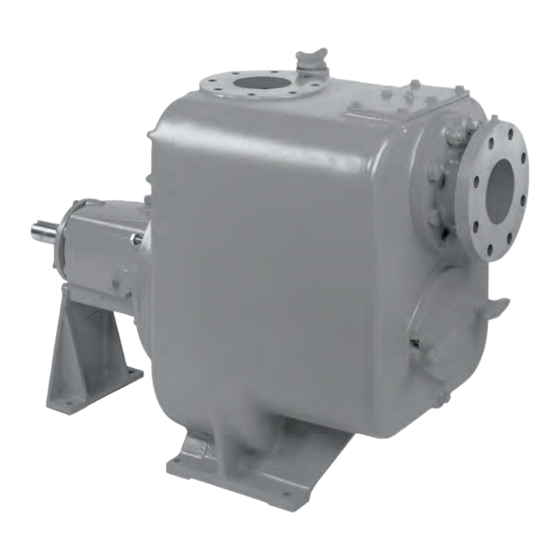
3 Product Description 3 Product Description Model Trash Hog II Installation, Operation, and Maintenance Manual... -
Page 16: Installation
Electrical connections must be made by certified electricians in compliance with all inter- national, national, state and local regulations. • Supervision by an authorized ITT representative is recommended to ensure proper instal- lation. Improper installation may result in equipment damage or decreased performance. 4.1.1 Pump location guidelines 4.1.2 Foundation requirements... - Page 17 4.1 Pre-installation Put the sets of wedges or shims on each side of each foundation bolt. Shims or wedges Figure 3: Top view Shims or wedges Figure 4: Side view Lower the baseplate carefully onto the foundation bolts. Put the machinist's levels across the mounting pads of the driver and the mounting pads of the pump.
- Page 18 4.1 Pre-installation Item Description Jackscrew Baseplate Foundation Plate Figure 5: Jackscrews Level the driver mounting pads: NOTICE: Remove all dirt from the mounting pads in order to ensure that the correct leveling is achieved. Failure to do so can result in equipment damage or decreased performance. Put one machinist's level lengthwise on one of the two pads.
- Page 19 4.1 Pre-installation 4.1.3.4 -leveling worksheet Level measurements 1)____________________ 2)____________________ 3)____________________ 4)____________________ 5)____________________ 6)____________________ 7)____________________ 8)____________________ 9)____________________ 10)___________________ 11)___________________ 12)___________________ 13)___________________ 14)___________________ 15)___________________ 16)___________________ 17)___________________ 18)___________________ Model Trash Hog II Installation, Operation, and Maintenance Manual...
- Page 20 4.1 Pre-installation 4.1.3.5 Install the pump, driver, and coupling Mount the driver on the . Use applicable bolts and hand tighten. Install the coupling. See the installation instructions from the coupling manufacturer. 4.1.3.6 Alignment checks When to perform alignment checks You must perform alignment checks under these circumstances: •...
- Page 21 4.1 Pre-installation Attach two dial indicators on the pump coupling half (X): Attach one indicator (P) so that the indicator rod comes into contact with the perimeter of the driver coupling half (Y). This indicator is used to measure parallel misalignment. Attach the other indicator (A) so that the indicator rod comes into contact with the inner end of the driver coupling half.
- Page 22 4.1 Pre-installation Figure 7: Vertical correction of the motor 4.1.3.11 Perform angular alignment for a horizontal correction Set the angular alignment indicator (A) to zero on left side of the driver coupling half (Y), 90° from the top-center position (9 o’clock). Rotate the indicator through the top-center position to the right side, 180°...
- Page 23 4.1 Pre-installation Figure 8: Horizontal correction of the motor 4.1.3.12 Perform parallel alignment for a vertical correction Refer to the alignment table in "Permitted indicator values for alignment checks" (see Table of Contents for location of table) for the proper cold alignment value based on the motor temperature rise and the pump operating temperature.
- Page 24 The specified permitted reading values are valid only at operating temperature. For cold set- tings, other values are permitted. The correct tolerances must be used. Failure to do so can result in misalignment. Contact ITT for further information. 4.1.3.13 Perform parallel alignment for a horizontal correction Refer to the alignment table in "Permitted indicator values for alignment checks"...
- Page 25 4.1 Pre-installation Figure 10: Horizontal correction of the motor Repeat the previous steps until the permitted reading value is achieved. 4.1.3.14 Perform complete alignment for a vertical correction Set the angular and parallel dial indicators to zero at the top-center position (12 o’clock) of the driver coupling half (Y).
- Page 26 4.1 Pre-installation Straight edge Incorrect Correct Figure 11: V-belt alignment When installing new belts, shorten center distance between sheaves so that belts can be put on without the use of force. NEVER "roll" or "pry" the belts into place, as this could damage the belt cords.
- Page 27 4.1 Pre-installation 4.1.3.17 V-Belt Alignment Although alignment is not as critical in V-belt drives as in others, proper alignment is essential for long belt and sheave life. First, make sure that drive shafts are parallel. The most common causes of mis- alignment are non-parallel shafts and improperly located sheaves.
-
Page 28: Grout The Baseplate
When to install a minimum-flow orifice You can size and install a minimum-flow orifice in a bypass line in order to prevent bypassing excessive flows. Consult your ITT representative for assistance in sizing a minimum-flow orifice. When a minimum-flow orifice is unavailable Consider an automatic recirculation control valve or solenoid-operated valve if a constant bypass (mini- mum-flow orifice) is not possible. - Page 29 Refer to Hydraulic Institute Standards general guideline for sump design. 4.1.6.1 Valves ITT does not recommend the use of a valve on the suction line EXCEPT: a) In case where positive suction heads are present in the line EXCEPT: b) Where it is possible for a positive head to develop due to flooding conditions.
-
Page 30: Discharge Piping
4.1 Pre-installation Gate and check valves may be used on the discharge side, but it is not necessary in low dis- charge head applications. It is recommended to use a throttling valve and check valve in the discharge line to protect the pump from excessive shock or water hammer and reversed rotation when pump is stopped. - Page 31 4.1 Pre-installation Liquid source below the pump Check Explanation/comment Checked Make sure that the suction piping is free This helps to prevent the occurrence of air and cavita- from air pockets. tion in the pump inlet. Check that the suction piping slopes up- —...
-
Page 32: Air Release Line
However, the preferred location is in the discharge line- between the pump and the discharge check valve-as close to the discharge check valve as possible. We recommend the following line sizes for the following ITT pumps. 3DTH & 4DTH 3/4"... -
Page 33: Commissioning, Startup, Operation, And Shutdown
"Trouble Guide" paragraph. ITT self priming pumps prime and reprime themselves providing the casing is filled with liquid. Should you lose this liquid from the casing accidentally or by draining purposely, it will be necessary to fill casing with liquid before starting. -
Page 34: Install The Coupling Guard
5.3 Install the coupling guard Foreign objects in the pumped liquid or piping system can block the flow and cause excess heat generation, sparks and premature failure. Make sure that the pump and systems are free of for- eign objects before and during operation. Electrical connections must be made by certified electricians in compliance with all international, national, state and local regulations. - Page 35 5.3 Install the coupling guard Item Description Annular groove Pump-side end plate Driver Pump half of the coupling guard Figure 15: Guard half installation The annular groove in the coupling guard half must fit around the end plate. Item Description Annular groove End plate (pump end) Guard half...
-
Page 36: Lubrication
5.4 Lubrication Item Description Washer Bolt Figure 17: Secure coupling guard half to end plate Put the driver half of the coupling guard in place: Slightly spread the bottom apart. Place the driver half of the coupling guard over the pump half of the coupling guard. The annular groove in the coupling guard half must face the motor. -
Page 37: Impeller Running Clearance
5.5 Impeller Running Clearance If pump is oil mist lubrication, check that the mist is flowing properly prior to starting pump. Use good grade SAE #30 non-detergent motor oil. Units are shipped without oil but should be checked before starting. Fill seal cavity with oil through hole provided on top of bearing housing nearest pump casing, until you see oil through hole opening. - Page 38 5.5 Impeller Running Clearance Tighten one set of screws and loosen the other to go in the direction required. Tighten locknut (111). NOTICE: Maximum allowable bearing carrier (110) pull back movement is 1/8", (i.e. from the condition when impeller is "just" touching the wearplate you can push back the bearing carrier assembly by 1/8").
-
Page 39: Maintenance
6 Maintenance 6 Maintenance 6.1 Shaft and Bearing Replacement If shaft or bearing replacement is necessary, follow these instructions. (Shut down the pump and discon- nect power supply to the pump before working on pump.) Install the front (impeller end) bearing (36) on the shaft (38). Slide the carrier retaining ring (106) onto the shaft (38). -
Page 40: Disassembly
Removing pipe plug from check valve cover plate (76). Installing a pet cock valve (not supplied by ITT) in place of pipe plug. With pet cock open fill casing (1) with fluid being pumped through filler plug (98) provided on top of casing. -
Page 41: Drain The Pump
6.5 Disassembly 6.5.3 Drain the pump 6.5.4 Disassembly If you need to replace impeller, wear plate, shaft seal, front oil lip seal, bearing or check valve, follow these steps: Drain pump casing completely by removing drain plug (2) from both suction and discharge chamber. Drain seal cavity oil by removing drain plug (27) from bearing housing. -
Page 42: Preassembly Inspections
6.6 Preassembly inspections 16. Check the bearings. If they feel rough when turning by hand, replace the bearings. Remove bear- ings (36 & 117) from the shaft (38) using a hydraulic press. 17. If your pump is supplied with a shaft sleeve (24), the sleeve is locked in place with a roll pin (101) and an a ring (104) to prevent leakage under the shaft. -
Page 43: Bearing-Frame Inspection
6.7 Reassembly 6.6.2 Bearing-frame inspection Checklist Check the bearing frame for these conditions: • Visually inspect the bearing frame and frame foot for cracks. • Check the inside surfaces of the frame for rust, scale, or debris. Remove all loose and foreign ma- terial. - Page 44 6.9 Winter Storage 10. Once a month rotate the pump shaft during the storage period to avoid freeze up and to lubricate the bearings. Model Trash Hog II Installation, Operation, and Maintenance Manual...
-
Page 45: Troubleshooting
7 Troubleshooting 7 Troubleshooting 7.1 Troubleshooting Guide NOTICE: Should pump be handling a harmful liquid, make sure necessary safety precautions are under- taken before implementing any recommended action in the accompanying Trouble Guide. The following are some common causes of problems that may arise: Table 2: Trouble Guide Symptoms Probable Cause... - Page 46 7.1 Troubleshooting Guide Symptoms Probable Cause Recommended Action • worn bearings • Replace or rebuild Excessive clearance be- Adjust to .020" to .030" clear- tween impeller and wear ance. (Follow instructions on plate. other pages.) Noisy Operation. Worn motor bearings. Replace.
-
Page 47: Pump Spare Parts List
8 Pump Spare Parts List 8 Pump Spare Parts List Description Description Casing Lockwasher Pipe Plug Lockwasher Locknut, Impeller Bushing Washer, Curved Hexnut Gasket, DiecuUMolded Stud Gasket, Diecut Cover, Check Valve Cover, Stuffing Box Gasket, Diecut Stud Lockwasher Lockwasher Handknob ***17 Seal, Single Mech. -
Page 48: Trash Hog Ii Type El Long Coupled
8.1 Trash Hog II Type EL Long Coupled 8.1 Trash Hog II Type EL Long Coupled Text of first paragraph. Table 3: Pump Parts List for Section Drawing Description Description Description Casing Pipe Plug Key, Impeller Impeller, Open Pipe Plug Shaft Elbow Locknut, Impeller... -
Page 49: Pump Spare Parts List
8.2 Pump Spare Parts List Description Description Description Locknut, Impeller Gasket, Molded Bearing Bearing Plate, Wear Screw, Shoulder 8.2 Pump Spare Parts List Description Description Casing Lockwasher Pipe Plug Lockwasher Locknut, Impeller Bushing Washer, Curved Hexnut Gasket, DiecuUMolded Stud Gasket, Diecut Cover, Check Valve Cover, Stuffing Box Gasket, Diecut... -
Page 50: Trash Hog Ii Type El Long Coupled
8.3 Trash Hog II Type EL Long Coupled 8.3 Trash Hog II Type EL Long Coupled Model Trash Hog II Installation, Operation, and Maintenance Manual... - Page 51 Goulds Pumps 240 Fall Street Seneca Falls, NY 13148 Form IOM.TrashHogII.en-US.2022-03 ©2022 ITT Corporation The original instruction is in English. All non-English instructions are translations of the original instruction.
Need help?
Do you have a question about the Goulds Pumps Trash Hog II and is the answer not in the manual?
Questions and answers