ITT Goulds Pumps XHD Installation, Operation And Maintenance Manual
Hide thumbs
Also See for Goulds Pumps XHD:
- Installation, operation and maintenance manual (160 pages) ,
- Installation, operation and maintenance manual (155 pages)
Table of Contents
Advertisement
Quick Links
Advertisement
Table of Contents
Troubleshooting

Related Manuals for ITT Goulds Pumps XHD


Summary of Contents for ITT Goulds Pumps XHD
- Page 1 Installation, Operation, and Maintenance Manual...
-
Page 3: Table Of Contents
Table of Contents Table of Contents Introduction and Safety ......................4 Introduction ..........................4 Safety ............................4 Safety terminology and symbols ................... 4 Environmental safety ......................5 User safety ........................... 6 Safety regulations for Ex-approved products in potentially explosive atmospheres ..... 7 Product approval standards .................... - Page 4 Table of Contents Commissioning, Startup, Operation, and Shutdown ............40 Preparation for startup ......................40 Remove the V-belt drive guard ..................... 40 Remove the coupling guard ....................41 Check the rotation ......................... 42 Impeller-clearance check ...................... 42 Impeller axial clearances ....................42 Impeller-clearance setting .....................
- Page 5 Assembly drawings (exploded views) ................. 111 Certification: CE or CE ATEX ..................... 117 Certificates of conformance ....................117 Other Relevant Documentation or Manuals ..............123 Local ITT Contacts ......................124 Regional offices ........................124 XHD Installation, Operation, and Maintenance Manual...
-
Page 6: Introduction And Safety
This includes any modification to the equipment or use of parts not provided by ITT. If there is a question regarding the intended use of the equipment, please contact an ITT representative before proceeding. -
Page 7: Environmental Safety
• Clean up all spills in accordance with safety and environmental procedures. • Report all environmental emissions to the appropriate authorities. WARNING: Do NOT send the product to the ITT manufacturer if it has been contaminated by any nuclear radiation. Inform ITT so that accurate actions can take place. Electrical installation For electrical installation recycling requirements, consult your local electric utility. -
Page 8: User Safety
Introduction and Safety Recycling guidelines Always follow local laws and regulations regarding recycling. User safety General safety rules These safety rules apply: • Always keep the work area clean. • Pay attention to the risks presented by gas and vapors in the work area. •... -
Page 9: Safety Regulations For Ex-Approved Products In Potentially Explosive Atmospheres
Introduction and Safety Precautions during work Observe these safety precautions when you work with the product or are in connection with the product: • Never work alone. • Always wear protective clothing and hand protection. • Stay clear of suspended loads. •... - Page 10 These are the personnel requirements for Ex-approved products in potentially explosive atmospheres: • All work on the product must be carried out by certified electricians and ITT-authorized mechanics. Special rules apply to installations in explosive atmospheres. • All users must know about the risks of electric current and the chemical and physical characteristics of the gas and/or vapor present in hazardous areas.
-
Page 11: Product Approval Standards
Introduction and Safety Equipment for monitoring For additional safety, use condition-monitoring devices. Condition-monitoring devices include but are not limited to these devices: • Pressure gauges • Flow meters • Level indicators • Motor load readings • Temperature detectors • Bearing monitors •... -
Page 12: Product Warranty
• The monitoring equipment incorporated in the product is correctly connected and in use. • All service and repair work is done by ITT-authorized personnel. • Genuine ITT parts are used. • Only Ex-approved spare parts and accessories authorized by ITT are used in Ex-approved products. Limitations The warranty does not cover faults caused by these situations: •... -
Page 13: Transportation And Storage
Transportation and Storage Transportation and Storage Inspect the delivery Inspect the package 1. Inspect the package for damaged or missing items upon delivery. 2. Note any damaged or missing items on the receipt and freight bill. 3. File a claim with the shipping company if anything is out of order. If the product has been picked up at a distributor, make a claim directly to the distributor. - Page 14 Transportation and Storage Pump type Lifting method A base-mounted pump Use slings under the pump casing and the drive unit, under the base rails, or through lifting lugs, when provided. Examples Figure 1: Example of bare pump proper lifting method Figure 2: Example of base mounted pump proper lifting method XHD Installation, Operation, and Maintenance Manual...
- Page 15 Transportation and Storage Figure 3: Example of overhead mounted pump proper lifting method Figure 4: Example of offset overhead motor mount pump proper lifting method XHD Installation, Operation, and Maintenance Manual...
-
Page 16: Storage Guidelines
You can purchase long-term storage treatment with the initial unit order or you can purchase it and apply it after the units are already in the field. Contact your local ITT sales representative. Frostproofing This table shows to what degree the pump is frostproof: When the pump is... -
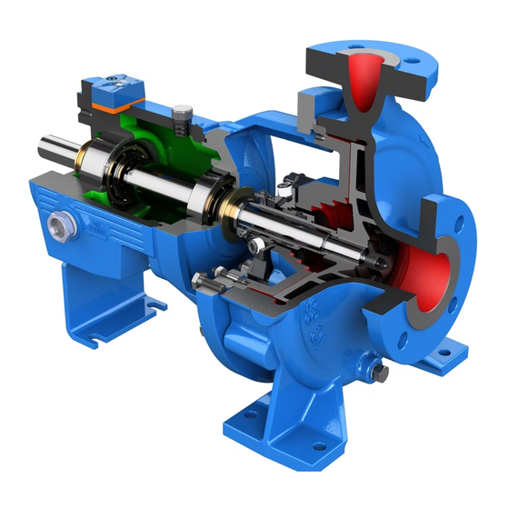
Page 17: Product Description
Product Description Product Description General description The XHD is a fully metric, frame-mounted, single stage, end suction extra heavy duty metal- lined slurry pump. Pump discharge diameter The metric size designation represents the pump discharge diameter. Metric size designation Suction x discharge x Suction x discharge x Power frame size impeller (mm) - Page 18 Product Description Heaviest pump component weight Size Item no. Part name Weight (lb) Weight (kg) Wet end Bare pump weight lbs (kg) weight less motor base/ motor lbs (kg) XHD80 100A Suction half 473 (215) 938 (431) casing XHD125 100A Suction half 1063 (483) 1750 (796)
-
Page 19: General Description I-Alert™ Condition Monitor
Goulds Pump Inc. model. Title, ownership rights, and intellectual property rights in and to the Software remain in ITT or its third-party providers. You agree that this license agreement does not need to be signed for it to take effect. -
Page 20: Nameplate Information
Product Description Nameplate information Important information for ordering Every pump has nameplates that provide information about the pump. The nameplates are located on the casing and the bearing frame. When you order spare parts, identify this pump information: • Model •... - Page 21 NOTICE:Make sure that the code classifications on the pump are compatible with the specific environment in which you plan to install the equipment. If they are not compatible, do not operate the equipment and contact your ITT representative before you proceed. XHD Installation, Operation, and Maintenance Manual...
-
Page 22: Installation
• You must earth (ground) all electrical equipment. This applies to the pump equipment, the driver, and any monitoring equipment. Test the earth (ground) lead to verify that it is connected correctly. NOTICE:Supervision by an authorized ITT representative is recommended to ensure proper installation. Failure to do so may result in equipment damage or decreased performance. -
Page 23: Baseplate-Mounting Procedures
Installation • Sleeve-type and J-type foundation bolts are most commonly used. Both designs allow movement for the final bolt adjustment. Sleeve-type bolts 1. Baseplate 2. Shims or wedges 3. Foundation 4. Sleeve 5. Dam 6. Bolt J-type bolts 1. Baseplate 2. -
Page 24: Install The Baseplate Using Shims Or Wedges
Installation Install the baseplate using shims or wedges Required tools: • Two sets of shims or wedges for each foundation bolt • Two machinist's levels • Baseplate-leveling worksheet This procedure is applicable to cast iron and fabricated steel baseplates. 1. If you use sleeve-type bolts, fill the bolt sleeves with packing material or rags to prevent grout from entering the bolt holes. - Page 25 Installation • Anti-seize compound • Jackscrews • Bar stock • Two machinist's levels • Baseplate-leveling worksheet This procedure is applicable to the feature-fabricated steel baseplate and the advantage base baseplate. 1. Apply an anti-seize compound on the jackscrews. The compound makes it easier to remove the screws after you grout. 2.
- Page 26 Installation 3. Level the driver mounting pads: NOTICE:Remove all dirt from the mounting pads in order to make sure that you achieve the correct leveling. Failure to do so can result in equipment damage or decreased performance. a) Put one machinist's level lengthwise on one of the two pads. b) Put the other machinist's level across the ends of the two pads.
- Page 27 Installation 7. Check that the driver's mounting pads are level and adjust the jackscrews and the foundation bolts if necessary. The correct level measurement is a maximum of 0.002 in./ft (0.0167 mm/m). XHD Installation, Operation, and Maintenance Manual...
-
Page 28: Direct-Coupled Baseplate-Leveling Worksheet
Installation Direct-coupled baseplate-leveling worksheet XHD Installation, Operation, and Maintenance Manual... -
Page 29: Install Pump, Driver, And V-Belt Drive
Installation Install pump, driver, and v-belt drive Install and align the sheaves Before installing the driver onto an overhead motor mount or side-by-side base, ensure that Foundation requirements and baseplate mounting procedures sections are complete. 1. Mount and fasten the pump on the pedestal spacer, foundation, or baseplate as applicable. Use appropriate hardware. -
Page 30: Install The Pump, Driver, And Coupling
Installation 2. After the belts are seated in the sheave grooves, increase the center distance between the pump and motor shafts to tension the belts. Refer to pump general arrangement drawing for center distance ranges. Figure 7: V-belt tension Many v-belt drive manufacturers offer tension measurement tools that can aid in setting proper belt tension. -
Page 31: Alignment Checks
Installation Alignment checks When to perform alignment checks You must perform alignment checks under these circumstances: • The process temperature changes. • The piping changes. • The pump has been serviced. Types of alignment checks Type of check When it is used Initial alignment (cold alignment) Prior to operation when the pump and the driver are at ambient check... -
Page 32: Alignment Measurement Guidelines
Installation Alignment measurement guidelines Guideline Explanation Rotate the pump coupling half and the driver This prevents incorrect measurement. coupling half together so that the indicator rods have contact with the same points on the driver coupling half. Move or shim only the driver in order to make This prevents strain on the piping installations. - Page 33 Installation 3. Record the indicator reading. When the reading value is... Then... Negative The coupling halves are farther apart at the bottom than at the top. Perform one of these steps: • Add shims in order to raise the feet of the driver at the shaft end.
- Page 34 Installation 3. Record the indicator reading. When the reading value is... Then... Negative The pump coupling half (X) is lower than the driver coupling half (Y). Remove shims of a thickness equal to half of the indicator reading value under each driver foot. Positive The pump coupling half (X) is higher than the driver coupling half (Y).
-
Page 35: Grout The Baseplate
Installation Perform complete alignment for a vertical correction A unit is in complete alignment when both the angular indicator (A) and the parallel indicator (P) do not vary by more than 0.002 in. (0.05 mm) as measured at four points 90° apart. 1. -
Page 36: Piping Checklists
Installation 6. Fill the remainder of the baseplate with grout, and allow the grout to set for at least 48 hours. 1. Baseplate 2. Grout 3. Foundation 4. Dam 5. Bolt 7. Tighten the foundation bolts. 8. Recheck the alignment. Piping checklists General piping checklist Precautions... -
Page 37: Suction-Piping Checklist
Installation Check Explanation/comment Checked Make sure that all the piping joints This prevents air from entering the piping system or and fittings are airtight. leaks that occur during operation. If the pump handles corrosive — fluids, make sure that the piping allows you to flush out the liquid before you remove the pump. - Page 38 Installation Check Explanation/comment Checked If suction strainers or suction bells Suction strainers help to prevent are used, check that they are at clogging. least three times the area of the Mesh holes with a minimum diam- suction piping. eter of 1/16 in. (1.6 mm) are recommended.
-
Page 39: Discharge Piping Checklist
Installation Example: Elbow (or other flow disruption) close to the pump suction inlet Correct Incorrect The correct distance between the inlet flange of the pump and the closest flow disruption (elbow, valve, strainer, or expansion joint) must be a least five pipe diameters. -
Page 40: Bypass-Piping Considerations
When to install a minimum-flow orifice You can size and install a minimum-flow orifice in a bypass line in order to prevent bypassing excessive flows. Consult your ITT representative for assistance in sizing a minimum-flow orifice. When a minimum-flow orifice is unavailable Consider an automatic recirculation control valve or solenoid-operated valve if a constant bypass (minimum-flow orifice) is not possible. -
Page 41: Auxiliary-Piping Checklist
Installation Auxiliary-piping checklist Precautions WARNING: • Cooling systems such as those for bearing lubrication and mechanical-seal systems must be operating properly to prevent excess heat generation, sparks, and premature failure. • Sealing systems that are not self-purging or self-venting, such as plan 23, require manual venting prior to operation. -
Page 42: Commissioning, Startup, Operation, And Shutdown
Commissioning, Startup, Operation, and Shutdown Commissioning, Startup, Operation, and Shutdown Preparation for startup WARNING: • Failure to follow these precautions before you start the unit will lead to serious personal injury and equipment failure. • Do not operate the pump below the minimum rated flows or with the suction or discharge valves closed. -
Page 43: Remove The Coupling Guard
Commissioning, Startup, Operation, and Shutdown 3. Disassemble and remove the drive guard assembly. Remove the coupling guard 1. Remove the nut, bolt, and washers from the slotted hole in the center of the coupling guard. 2. Slide the driver half of the coupling guard toward the pump. 3. -
Page 44: Check The Rotation
Commissioning, Startup, Operation, and Shutdown Check the rotation WARNING: • Operating the pump in reverse rotation can result in the contact of metal parts, heat generation, and breach of containment. • Always disconnect and lock out power to the driver before you perform any installation or maintenance tasks. - Page 45 Commissioning, Startup, Operation, and Shutdown WARNING: • The pump should be run for a period of 15 minutes to verify the impeller is properly tightened onto the shaft. In addition to verifying the impeller is properly tightened, it is necessary to verify that the bearing frame adjustment plate bolts (352G) and nuts (427D) are properly secured and tight.
-
Page 46: Set Impeller To Suction Seal Ring Clearance Dial Indicator Method
Commissioning, Startup, Operation, and Shutdown Set impeller to Suction Seal Ring Clearance Dial Indicator Method WARNING: Always disconnect and lock out power to the driver before you perform any installation or maintenance tasks. Failure to disconnect and lock out driver power will result in serious physical injury. All of the instructions that are stated in the following steps are based on viewing the unit from the rearward (drive) end. - Page 47 Commissioning, Startup, Operation, and Shutdown 8. Tighten the adjustment plate hold-down bolts (352G) and nuts (427D) that clamp the bearing frame adjustment plates (234F) to the pedestal (131). Make sure that the dial indicator reading remains at the proper setting. 9.
-
Page 48: Set Impeller Clearance Dial Indicator Method - Xhd
Commissioning, Startup, Operation, and Shutdown Table 6: Impeller clearance Pump Size Field Setting Impeller Back Field Setting Impeller Front Clearance inches (mm) Clearance inches (mm) XHD80 0.08 (2) 0.02 (.51) XHD125 0.08 (2) 0.02 (.51) XHD150 0.08 (2) 0.02 (.51) XHD200 0.1 (2.5) 0.02 (.51) -
Page 49: Suction Seal Ring Clearance Check - Xhd Only
Commissioning, Startup, Operation, and Shutdown 9. Tighten the two adjusting nuts (415A) on the rearward side of the bearing frame adjustment plates (234F) that were loosened in step 5 above by turning them clockwise. Make sure that the dial indicator reading remains at the proper setting. 10. -
Page 50: V-Belt Drive Operation
Commissioning, Startup, Operation, and Shutdown V-Belt drive operation V belt drive installation checks Use the following steps and guidelines to make sure that the v-belt drive is properly installed and that the belts are properly tensioned. 1. Operate the drive for a few minutes as the belts seat into the sheave grooves. 2. -
Page 51: Couple The Pump And Driver
Commissioning, Startup, Operation, and Shutdown Couple the pump and driver WARNING: Always disconnect and lock out power to the driver before you perform any installation or maintenance tasks. Failure to disconnect and lock out driver power will result in serious physical injury. Couplings must have proper certification to be used in an ATEX classified environment. -
Page 52: Install The Coupling Guard
Commissioning, Startup, Operation, and Shutdown Install the coupling guard WARNING: • Never operate a pump without a properly installed coupling guard. Personal injury will occur if you run the pump without a coupling guard. • Always disconnect and lock out power to the driver before you perform any installation or maintenance tasks. - Page 53 Commissioning, Startup, Operation, and Shutdown 2. Put the pump-side end plate in place. If the pump-side end plate is already in place, make any necessary coupling adjustments and then proceed to the next step. 3. Put the pump-half of the coupling guard in place: a) Slightly spread the bottom apart.
-
Page 54: Bearing Lubrication
Commissioning, Startup, Operation, and Shutdown 4. Use a bolt, a nut, and two washers to secure the coupling guard half to the end plate. Tighten securely. 1. Nut 2. Washer 3. Bolt 5. Put the driver half of the coupling guard in place: a) Slightly spread the bottom apart. -
Page 55: Lubricate The Bearings With Oil
Commissioning, Startup, Operation, and Shutdown Lubricate the bearings with oil WARNING: Make sure to properly lubricate the bearings. Failure to do so can result in excess heat generation, sparks, and premature failure. 1. Remove the oil fill pipe plug (319B). 2. -
Page 56: Packed Stuffing Box Option
Commissioning, Startup, Operation, and Shutdown Method Description External flush Run the piping so that the pump injects a clean, cool, compatible liquid directly into the seal gland. The pressure of the flushing liquid must be 5 to 15 psi (0.35 to 1.01 kg/cm ) greater than the seal chamber pressure. - Page 57 Commissioning, Startup, Operation, and Shutdown Pumps are shipped without the packing, lantern ring, or split gland installed. These parts are included with the box of fittings shipped with each pump and must be installed before startup. 1. Carefully clean the stuffing-box bore. 2.
- Page 58 Commissioning, Startup, Operation, and Shutdown 3. Insert the packing and stagger the joints in each ring by 90º. Install the stuffing box parts in this order: For weep flush setting (2L3): a) Two packing rings (106) b) One lantern ring (105) c) Three packing rings (106) 1.
-
Page 59: Pump Priming
Commissioning, Startup, Operation, and Shutdown 4. Install the gland halves and evenly hand-tighten the nuts. Do not overtighten gland nuts. Overtightened packing causes excessive friction between packing and sleeve and will result in damaged components. Table 7: Flush water requirements The flush water requirements are listed for both the weep style and full flush packing arrangements. - Page 60 Commissioning, Startup, Operation, and Shutdown 1. Discharge isolation valve 2. Shutoff valve 3. From outside supply 4. Foot valve 5. Check valve This illustration is an example of priming the pump with a foot valve using a bypass around the check valve: 1.
-
Page 61: Other Methods Of Priming The Pump
Commissioning, Startup, Operation, and Shutdown Other methods of priming the pump You can also use these methods in order to prime the pump: • Prime by ejector • Prime by automatic priming pump Start the pump CAUTION: • Immediately observe the pressure gauges. If discharge pressure is not quickly attained, stop the driver, reprime, and attempt to restart the pump. -
Page 62: I-Alert™ Condition Monitor Routine Operation
The condition monitor is ready for activation when the pump is running and has reached a steady flow, pressure, and temperature. This process only takes a few minutes. 1. Place a small magnet on the condition monitor over the ITT logo and then remove it, as this example shows. -
Page 63: Pump Operation Precautions
Commissioning, Startup, Operation, and Shutdown Pump operation precautions General considerations CAUTION: • Vary the capacity with the regulating valve in the discharge line. Never throttle the flow from the suction side since this can result in decreased performance, unexpected heat generation, and equipment damage. -
Page 64: Reset The I-Alert™ Condition Monitor
Commissioning, Startup, Operation, and Shutdown 1. Touch and hold a small magnet to the condition monitor over the ITT logo until the red LEDs blink three times. This should take 10-15 seconds if the condition monitor is in normal operating mode and approximately five seconds if the condition monitor is in alarm mode. -
Page 65: Maintenance
Maintenance Maintenance Maintenance schedule Maintenance inspections A maintenance schedule includes these types of inspections: • Routine maintenance • Routine inspections • Three-month inspections • Annual inspections Shorten the inspection intervals appropriately if the pumped fluid is abrasive or corrosive or if the environment is classified as potentially explosive. -
Page 66: Bearing Maintenance
Maintenance 3. Replace worn parts. Bearing maintenance Bearing lubrication schedule Type of bearing First lubrication Lubrication intervals Oil-lubricated bearings Add oil before you install and start After the first 200 hours, change the pump. Change the oil after the oil every 1000 operating hours 200 hours for new bearings. - Page 67 Maintenance Grease recommendations Use a lithium-based mineral-oil grease with a consistency of NLGI 2 with EP additives. This table shows which brand and type of greae to use when lubricating the pump. Brand Grease type Castrol Castrol EPL2 Exxon Unirex EP2 Lubriplate SYN 1602 Mobil...
-
Page 68: Shaft-Seal Maintenance
Maintenance Lubricate the bearings after a shutdown period 1. Flush out the bearings and bearing frame with a light oil to remove contaminants. During flushing, make sure to rotate the shaft slowly by hand. 2. Flush the bearing housing with the proper lubricating oil to ensure oil quality after cleaning. Shaft-seal maintenance Mechanical-seal maintenance WARNING:... - Page 69 Maintenance Tightening of packing NOTICE:Never over-tighten packing to the point where less than one drop per second is observed. Over-tightening can cause excessive wear and power consumption during opera- tion. If you cannot tighten the packing to obtain less than the specified leakage rate, then replace the packing.
-
Page 70: Disassembly
Maintenance The lantern ring connection can be used to inject flush liquid or grease when required on specific applications. Drain tap The drain tap allows you to drain the liquid that remains in the expeller chamber upon pump shutdown. Consider removing this liquid before you service the pump in order to prevent it from hardening, or protect the pump during freezing weather. -
Page 71: Wet End Disassembly Instructions
Maintenance The XHD is a front pull out design. Typical disassembly steps can be followed for both the XHD and XHD Value Option. The suction half casing and attached components can be removed for further disassembly and replacement of the suction side liner (562) and adjustable seal ring (822, XHD only) as necessary. - Page 72 Maintenance 1. Support the suction half casing (100A) with a hoist hook through the lifting lug. Tension the hoist properly so the subassembly will be fully supported upon disengagement. 2. Remove the casing hex head nuts (600C) and flat washers (553) from the casing hex head bolts (600A) and tapered alignment studs (600D).
- Page 73 Maintenance 4. Remove the suction side liner flat gasket (351N). Remove the suction side liner and adjustable seal ring - XHD 1. Remove the jam nuts (357A) that attach the adjustable seal ring (822) and the suction side liner (562) to the suction half casing (100A). 2.
- Page 74 Maintenance 3. Remove the seal ring inner diameter o-rings (512A) and outer diameter o-rings (512B). The indicating roll pin (757A) can also be removed if necessary. Impeller removal Two people should work together to remove the impeller for safety purposes. 1.
- Page 75 Maintenance Stuffing box removal Pump Model Next step to follow • The stuffing box is split and can be disassem- bled prior to casing volute liner removal. Con- tinue with the Remove the split stuffing box step below. XHD Value Option •...
- Page 76 Maintenance 3. Move the casing volute liner (561) out of and away from the gland half casing. 4. Remove the seal cover-to-volute liner gasket (351Q). 5. Remove the volute liner retention studs (356K) from the casing volute liner (561) using a metric stud driver.
- Page 77 Maintenance 3. Hoist the casing assembly to the ground so that the seal cover or stuffing box cover can be removed. 4. Remove the seal cover retention hex head cap screws (388A) and clipped washers (354A). 5. Remove the seal cover (184) from the gland half casing (100D). Use a short pry bar to gently and evenly facilitate disassembly if necessary.
- Page 78 Locate and lift the volute liner for optional discharge locations (field replacement) 1. Using the ITT approved volute liner and Impeller lifting device, the Volute Liner (561) can be installed into the Gland Casing (100D) the field in any of the optional discharge orientations.
- Page 79 Maintenance 2. Remove the Suction casing and Suction Liner assembly as described in the section 'Remove the Suction Side. 3. Remove the Impeller as shown in the impeller removal section. XHD Installation, Operation, and Maintenance Manual...
-
Page 80: Remove The Power End - Quick Disconnect Option For Xhd
Maintenance 4. Secure the Volute Liner hook, to the Volute Liner (561) in the proper orientation, as illustrated below. 5. Lift the Hook and volute liner and crane into the Gland casing. 6. Be sure to locate the Volute Liner hook and upper and lower keys, and tighten the bolts thru the key to the hook. -
Page 81: Remove The Power End- Xhd And Xhd Value Option
Maintenance 3. Move the impeller to the back of the volute liner: Turn the two rearward (drive end side) bearing frame adjusting nuts (415A) on either side of the power frame sequentially clockwise, 1/2 turn of each nut at a time, to draw the bearing frame and impeller (101) backwards toward the volute liner (561). - Page 82 Maintenance 3. Slide the power end backwards away from the liquid end until the shaft is completely free of the liquid end and pedestal (131) lower half-ring. 4. Remove the outer bearing frame adjustment rod nuts (415A) and threaded rods (370X). 5.
-
Page 83: Disassemble The Power End - Xhd, Oil Lubrication
Maintenance 6. Remove the bearing frame adjustment plate bolts (352G), nuts (427D) and bearing frame adjustment plates (234F). 7. Tension the hoist fully to lift and move the power end to designated work area. Disassemble the power end - XHD, oil lubrication 1. - Page 84 Maintenance 4. Remove the Bellville preload washer (529). Important: Always remove the outboard bearing cover assembly and Bellville washer first. This will remove the preload from the rotating element assembly for easier removal of the remaining bearing frame components. 5. Remove the inboard bearing cover assembly hex head capscrews (370P). 6.
-
Page 85: Disassembly Of Other Power End Configurations
Maintenance 10. Remove the inboard and outboard taper roller bearings (409 and 410) using a suitable puller that only contacts the inner races of the bearings. 11. Remove and clean or replace bulls eye sight glass (319) and opposite sight glass (408N) if necessary. -
Page 86: Preassembly Inspections
Maintenance Disassemble the power end XHD Value Option, oil lubrication • The XHD oil lubricated power end uses double lip seals as bearing isolators. Instead of pipe plugs, there will be grease fitting plugs in the bearing cartridge end covers for the addition of grease as necessary to maintain the double lip seal contaminant barrier. -
Page 87: Reassembly
Maintenance • Check the inside surfaces of the frame for rust, scale, or debris. Remove all loose and foreign material. • Make sure that all lubrication passages are clear. • If the frame has been exposed to pumped fluid, inspect the frame for corrosion or pitting. •... - Page 88 Maintenance 9. Secure the inboard cover assembly to the bearing cartridge housing (228) using the hex head cap screws (370P). 10. Slide the bellville washer (529) and outer race of the inboard bearing (409) into position inside the bearing frame (228). 11.
-
Page 89: Assemble The Power End To The Pedestal
Maintenance 14. Lubricate the outboard bearing cover o-ring (412) and insert into the outboard bearing cover (109). 15. Slide the outboard bearing cover (with Inpro seal and o-ring attached) into the bearing cartridge housing (228) carefully to avoid o-ring damage. 16. - Page 90 Maintenance 3. Place the power end into position on the pedestal (131). 4. Place the bearing frame adjustment plates (234F) onto the pedestal (131) and bearing cartridge housing (228) rails. 5. Hand tighten the bearing frame adjustment plates (234F) to the pedestal (131) using the adjustment plate hex bolts (352G) and nuts (427D).
-
Page 91: Assembly Of Other Power End Configurations
Maintenance 6. Insert the free ends of the threaded adjustment rods (370X) through the bearing frame adjustment plate (234F) and outboard end cover (109) ears. 7. Secure the threaded adjustment rods (370X) to the bearing frame adjustment plates (234F) and outboard end cover (109) by installing the hex nuts (415A) on the outer face of the adjustment plate and end cover ears. -
Page 92: Wet End Assembly Instructions
Maintenance • There are also grease fitting plugs (319H) and grease relief plugs (319Y) installed into the bearing cartridge housing (228) used for purging and regreasing the grease lubricated XHD XL power end. • There will be no sight glass (319) or opposite sight glass (408N) on the grease lubricated power end Assemble the power end - XHD, oil lubrication, lip seals •... -
Page 93: Wet End Assembly Instructions
Maintenance 3. Position the knock-off ring onto the shaft (122). Make sure that the part is properly oriented. The larger diameter step of the knock-off ring should face the bearing cartridge housing (228). 4. Slide the knock-off ring towards the bearing cartridge housing until it is flush with the inboard end cover (160). - Page 94 Maintenance 3. Position the knock-off ring onto the shaft (122) and make sure that the part is properly oriented. The side of the knock-off ring that should face the impeller is marked "THIS SIDE OUT". 4. Slide the knock-off ring towards the bearing cartridge housing until it is flush with the inboard end cover (119).
- Page 95 Maintenance Install the gland half casing and seal cover 1. Install the tapered alignment studs (375B) into the gland half casing (100D) using a metric stud driver. a) Install the seal cover into the casing. b) With bolts and clipped washers (354A) (388A). 2.
- Page 96 Maintenance 5. Install the hex head capscrews (370Y) through the pedestal flange into the gland half casing (100D) to complete assembly. Stuffing box assembly and installation Pump model Next step to follow • Go to Install the seal cover instructions. XHD XL •...
- Page 97 Maintenance 3. Attach the stuffing box (159) to the seal cover (184) using the stuffing box-to-seal cover hex head cap screws (569L). 4. Trim edges of the stuffing box gasket such that they will not interfere with the stuffing box oring.
- Page 98 Maintenance 2. Insert the casing volute liner retention studs into the casing volute liner (561) using a metric stud driver. 3. Coat the seal cover-to-volute liner gasket (351Q) with lubricant and install into the casing volute liner (561). 4. Support the casing volute liner (561) using the proper end of the Goulds-provided impeller/ casing volute hook tool.
- Page 99 Maintenance 6. With one person holding the impeller steady, the other should turn the shaft (122) clockwise to screw the shaft into the impeller. Begin this operation by hand and finish with an adjustable spanner wrench. 7. After the shaft (122) has been tightly screwed into the impeller (101), the bearing frame can be slid backwards toward the drive end until the impeller sits completely recessed in the casing volute liner (561).
- Page 100 Maintenance 3. Lubricate and install the volute liner-to-suction side liner gasket (351N). After completion, skip the next step listed for the XHD and move onto the Install the suction half casing step. Install adjustable seal ring and suction side liner into suction half casing - XHD 1.
- Page 101 Maintenance 9. Install the seal ring hex jam nuts (357B) on the square head adjusting bolts (356F) that now protrude from the suction half casing (100A). Fully tighten to complete assembly. 10. Coat the volute liner-to-suction side liner flat gasket (351N) with lubricant and install into the suction side liner (561).
- Page 102 Maintenance 6. Install the flat washers (553) and casing bolt hex nuts (600C) onto the casing bolts (600A) to complete assembly of the casing halves. Install packing, lantern ring, and gland 1. Measure the appropriate length of packing (106) strips by wrapping packing around the shaft sleeve (126) to estimate the desired length.
-
Page 103: Assembly References
Maintenance 3. Install the suction joint flat gasket (351B). Assembly references Spare parts Recommended spare parts In order to prevent a long and costly downtime period, especially on critical services, it is advisable that you have these spare parts on hand: •... - Page 104 Maintenance Bearing bore fits and tolerances Group Bearing Maximum bearing frame bore in inches (millimeters) Inboard 5.1197 (130.040) Outboard Inboard 7.4821 (190.046) Outboard Inboard 10.2383 (260.052) Outboard Inboard 11.4193 (290.052) Outboard XHD Installation, Operation, and Maintenance Manual...
- Page 105 Maintenance Bolt torques for XHD80 Option Item Description Thread Torque (N- Torque (ft- number size lbs) Lubricated Lubricated (k=.15) (k=.15) Standard 600A Hex bolt, casing M20x2.5 117 Standard 600C Hex nut, casing Standard 600D Taper stud, casing alignment M20x2.5 458 Standard 415B Hex nut, taper stud Standard 356K...
- Page 106 Maintenance Bolt torques for XHD125 Option Item Description Thread Torque (N- Torque (ft- number size lbs) Lubricated Lubricated (k=.15) (k=.15) Standard 600A Hex bolt, casing M24x3 Standard 600C Hex nut, casing Standard 600D Taper stud, casing alignment M24x3 Standard 415B Hex nut, taper stud Standard 356K Stud, volute liner retention...
- Page 107 Maintenance Bolt torques for XHD150 Option Item Description Thread Torque Torque number size (N-m) (ft-lbs) Lubricat Lubricat (k=.15) (k=.15) Standard 600A Hex bolt, casing M30x3.5 377 Standard 600C Hex nut, casing Standard 600D Taper stud, casing alignment M30x3.5 1571 1163 Standard 415B Hex nut, taper stud Standard 356K...
- Page 108 Maintenance Bolt torques for XHD200 Option Item Description Thread Torque Torque number size (N-m) (ft-lbs) Lubricat Lubricat (k=.15) (k=.15) Standard 600A Hex bolt, casing M36x4 Standard 600C Hex nut, casing Standard 600D Taper stud, casing alignment M36x4 1571 1163 Standard 415B Hex nut, taper stud Standard 356K Stud, volute liner retention...
- Page 109 Maintenance Bolt Torques for XHD250 Option Item Description Thread Torque Torque number size (N-m) (ft-lbs) Lubricat Lubricat (k=.15) (k=.15) Standard 600A Hex bolt, casing M42x4.5 1141 Standard 600C Hex nut, casing Standard 600D Taper stud, casing alignment M42x4.5 1571 1163 Standard 415B Hex nut, taper stud Standard 356K...
- Page 110 Maintenance Bolt torques for XHD300 Option Item Description Thread Torque Torque number size (N-m) (ft-lbs) Lubricat Lubricat (k=.15) (k=.15) Standard 600A Hex bolt, casing M48x5 1659 1221 Standard 600C Hex nut, casing Standard 600D Taper stud, casing alignment M48x5 1571 1163 Standard 415B Hex nut, taper stud...
-
Page 111: Troubleshooting
Change the rotation. The rotation must match the arrow on the bearing housing or pump casing. The foot valve or suction pipe opening is not Consult an ITT representative for the proper sub- submerged enough. mersion depth. Use a baffle in order to eliminate vortices. -
Page 112: Alignment Troubleshooting
Replace the condition monitor. The unit is deactivated. Activate the condition monitor. The unit is malfunctioning. Consult your ITT representative for a warranty replacement. The red LEDs are flashing, but the temperature and The baseline is bad. Check the temperature and vi- vibration are at acceptable levels. -
Page 113: Parts Listings And Cross-Sectional Drawings
Parts Listings and Cross-Sectional Drawings Parts Listings and Cross-Sectional Drawings Assembly drawings (exploded views) Figure 15: XHD Standard oil lubrication Item Description High High Endura- Ultra High Chrome Chrome Chrome Chrome HC600 w/DI Seal Special 35% Cr Cover HC600/DI 100A Suction half casing 1018 XHD Installation, Operation, and Maintenance Manual... - Page 114 Parts Listings and Cross-Sectional Drawings Item Description High High Endura- Ultra High Chrome Chrome Chrome Chrome HC600 w/DI Seal Special 35% Cr Cover HC600/DI 100D Gland half casing 1018 Impeller 1228 1269 1650 Lantern ring 6308 Packing 5026 Gland half 1203 Bearing cover, outboard 1018...
- Page 115 Parts Listings and Cross-Sectional Drawings Item Description High High Endura- Ultra High Chrome Chrome w/ Chrome Chrome HC600 DI Seal Special HC 35% Cr Cover HC600/DI 367B Gasket, chamber 5145 370N Screw, hex cap (outboard bearing 2472 cover) 370P Screw, hex cap (inboard bearing cov- 2472 370Y Screw, hex cap (pedestal to gland half...
- Page 116 Parts Listings and Cross-Sectional Drawings Figure 16: Optional features XHD Installation, Operation, and Maintenance Manual...
- Page 117 Parts Listings and Cross-Sectional Drawings Figure 17: XHD Liquid end XHD Installation, Operation, and Maintenance Manual...
- Page 118 Parts Listings and Cross-Sectional Drawings Figure 18: XHD Oil lube power end XHD Installation, Operation, and Maintenance Manual...
-
Page 119: Certification: Ce Or Ce Atex
Certification: CE or CE ATEX Certification: CE or CE ATEX Certificates of conformance CSA Certificate XHD Installation, Operation, and Maintenance Manual... - Page 120 Certification: CE or CE ATEX XHD Installation, Operation, and Maintenance Manual...
- Page 121 Certification: CE or CE ATEX ATEX notification XHD Installation, Operation, and Maintenance Manual...
- Page 122 Certification: CE or CE ATEX IECEx Certificate of Conformity XHD Installation, Operation, and Maintenance Manual...
- Page 123 Certification: CE or CE ATEX XHD Installation, Operation, and Maintenance Manual...
- Page 124 Certification: CE or CE ATEX Chinese Certificate of Conformity XHD Installation, Operation, and Maintenance Manual...
-
Page 125: Other Relevant Documentation Or Manuals
Other Relevant Documentation or Manuals Other Relevant Documentation or Manuals For additional documentation For any other relevant documentation or manuals, contact your ITT representative. XHD Installation, Operation, and Maintenance Manual... -
Page 126: Local Itt Contacts
Local ITT Contacts Local ITT Contacts Regional offices Region Address Telephone North America (Headquarters) ITT - Goulds Pumps +1 315-568-2811 +1 315-568-2418 Asia Pacific ITT Industrial Process +65 627-63693 +65 627-63685 10 Jalan Kilang #06-01 Singapore 159410 Europe ITT - Goulds Pumps... - Page 128 Goulds Pumps Inc. 240 Fall Street Seneca Falls, NY 13148 Tel. 1-800-446-8537 Fax 1-315-568-2418 Form en-US.2012-08.IOM.XHD © 2012 ITT Corporation The original instruction is in English. All non-English instructions are translations of the original instruction.
Need help?
Do you have a question about the Goulds Pumps XHD and is the answer not in the manual?
Questions and answers