Table of Contents
Advertisement
Quick Links
Advertisement
Table of Contents

Related Manuals for ITT Goulds Pumps SRL


Summary of Contents for ITT Goulds Pumps SRL
- Page 1 Installation, Operation, and Maintenance Manual Model SRL, SRL-C, and SRL-XT...
-
Page 3: Table Of Contents
Table of Contents Table of Contents 1 Introduction and Safety ............................ 3 1.1 Introduction..............................3 1.2 Safety ................................ 3 1.2.1 Safety terminology and symbols ..................... 4 1.2.2 Environmental safety........................5 1.2.3 User safety ............................5 1.3 Product warranty ............................7 2 Transportation and Storage.......................... - Page 4 Table of Contents 6.4.1 Disassembly precautions ......................24 6.4.2 Tools required..........................24 6.4.3 Drain the pump..........................24 6.4.4 Disassemble the pump for size 1.5x1.5-8 and 2x2x10-SRL ............25 6.4.5 Disassemble the midsize pump ....................27 6.4.6 Disassemble the large pump......................28 6.5 Bearings inspection ..........................
-
Page 5: Introduction And Safety
Prohib- ited methods include any modification to the equipment or use of parts not provided by ITT. If there is any uncertainty regarding the appropriate use of the equipment, please contact an ITT representative before proceeding. -
Page 6: Safety Terminology And Symbols
Risk of injury and/or property damage. Operating a pump in an inappropriate application can cause over pressurization, overheating, and/or unstable operation. Do not change the service application without the approval of an authorized ITT representative. 1.2.1 Safety terminology and symbols... -
Page 7: Environmental Safety
WARNING: If the product has been contaminated in any way, such as from toxic chemicals or nuclear radi- ation, do NOT send the product to ITT until it has been properly decontaminated and advise ITT of these conditions before returning. - Page 8 1.2 Safety • First-aid kit • Safety devices Electrical connections Electrical connections must be made by certified electricians in compliance with all international, nation- al, state, and local regulations. For more information about requirements, see sections dealing specifical- ly with electrical connections. Noise WARNING: Sound pressure levels may exceed 80 dbA in operating process plants.
-
Page 9: Product Warranty
All service and repair work is done by ITT-authorized personnel. • Genuine ITT parts are used. • Only Ex-approved spare parts and accessories authorized by ITT are used in Ex-approved prod- ucts. Limitations The warranty does not cover faults caused by these situations: •... - Page 10 Economic losses Warranty claim ITT products are high-quality products with expected reliable operation and long life. However, should the need arise for a warranty claim, then contact your ITT representative. Model SRL, SRL-C, and SRL-XT Installation, Operation, and Maintenance Manual...
-
Page 11: Transportation And Storage
2 Transportation and Storage 2 Transportation and Storage 2.1 Inspect the delivery 2.1.1 Inspect the package Inspect the package for damaged or missing items upon delivery. Note any damaged or missing items on the receipt and freight bill. File a claim with the shipping company if anything is out of order. If the product has been picked up at a distributor, make a claim directly to the distributor. -
Page 12: Pump Storage Requirements
2.3 Pump storage requirements Pump type Lifting method A base-mounted pump Use slings under the pump casing and the drive unit, or under the base rails. 2.3 Pump storage requirements If you do not plan to install and operate the unit soon after arrival, adhere to these storage requirements: •... -
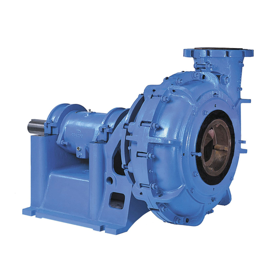
Page 13: Product Description
3 Product Description 3 Product Description 3.1 General description of the SRL The SRL is a horizontal, rubber-lined, end-suction centrifugal pump. This pump meets Hydraulic Institute standards and is available in four wet end configurations: • SRL – open impeller •... - Page 14 3.2 Nameplate information Nameplate on the pump casing using English units Figure 1: Nameplate on the pump casing using English units Table 4: Explanation of nameplate on the pump casing Nameplate field Explanation Serial number of the pump MODEL Pump model SIZE Size of the pump STD.
- Page 15 3.2 Nameplate information Nameplate field Explanation HYDRO PRESS Hydrostatic pressure at 20 °C, in kg/cm2 FLOW Rated pump flow in m3/hr R.P.M. Rated pump speed, revolutions per minute MAX. DES. WORKING PRESS. @°C Maximum working pressure at 20 °C, in kg/cm2 HEAD Rated pump head, in m MAT'L.
-
Page 16: Installation
4 Installation 4 Installation 4.1 Installation 4.1.1 Foundation The foundation should be sufficiently substantial to absorb any vibration, and to form a permanent rigid support for the pump. A concrete foundation, with foundation bolts of the proper size grouted in place to drawing dimensions, is recommended. -
Page 17: Commissioning, Startup, Operation, And Shutdown
5 Commissioning, Startup, Operation, and Shutdown 5 Commissioning, Startup, Operation, and Shutdown 5.1 Preparation for startup WARNING: • Risk of serious physical injury or death. Exceeding any of the pump operating limits (e.g. - pressure, temperature, power, etc.) could result in equipment failure, such as explosion, seizure, or breach of containment. -
Page 18: Check The Rotation
5.2 Check the rotation CAUTION: When a cartridge mechanical seal is used, ensure that the set screws in the seal locking ring are tightened and that the centering clips have been removed prior to startup. This prevents seal or shaft sleeve damage by ensuring that the seal is properly installed and centered on the sleeve. -
Page 19: Lubricating Oil Requirements
5.3 Lubricate the bearings All horizontal SRL, SRL-C, and SRL-XT pumps have anti-friction bearings that must be lubricated with oil before you start the pump. Flush the cylinder or frame liner with oil in order to remove any grit or dirt that might have entered the bearing housing during shipment or installation. -
Page 20: Grease Seal Requirements
5.4 Pump priming Size Model Liters Imperial quarts US quarts 10x10x28 SRL-XT 6.25 5.50 6.61 14x12x36 SRL-XT 10.11 8.90 10.69 5.3.3 Grease seal requirements Make sure that the grease you use in order to seal the bearing housing has these characteristics: •... -
Page 21: Start The Pump
5.6 Start the pump • Refer to driver/coupling/gear manufacturer's installation and operation manuals (IOM) for specific instructions and recommendations. Exposed rotating shaft between pump seal and bearing frame. Avoid contact and/or install proper guard- ing. If guarding is not provided with the pump, contact Goulds for price and availability of proper guard- ing. -
Page 22: Shut Down The Pump
5.8 Shut down the pump Operation at reduced capacity WARNING: • Risk of breach of containment and equipment damage. Excessive vibration levels can cause damage to bearings, stuffing box, seal chamber, and/or mechanical seal. Observe pump for vibration levels, bearing temperature, and excessive noise. If normal levels are exceeded, shut down and resolve. -
Page 23: Maintenance
6 Maintenance 6 Maintenance 6.1 Maintenance schedule Maintenance inspections A maintenance schedule includes these types of inspections: • Routine inspections • Three-month inspections • Annual inspections Shorten the inspection intervals appropriately if the pumped fluid is abrasive or corrosive or if the envi- ronment is classified as potentially explosive. -
Page 24: Stuffing Box Maintenance
6.2 Stuffing box maintenance If the pump performance does not satisfy your process requirements, and the process requirements have not changed, then perform these steps: Disassemble the pump. Inspect it. Replace worn parts. Three-month maintenance Drain oil and flush oil reservoir and bearings. Refill to proper level with recommended grade of lubricant Six-month maintenance •... -
Page 25: Gland Water Requirements
6.3 Gland water requirements Water requirements • Constantly supply the stuffing box with a source of clean, clear water in order to flush and lubricate the packing. • Supply the sealing water at about 10 psig above the discharge pressure of the pump, in quantities shown in Table 7: Gland water requirements on page •... -
Page 26: Disassembly
6.4 Disassembly • When you design the gland system, size it for 50% to 100% higher flows in order to allow for wear in the stuffing box bushing and increased flow due to fluctuations in the pressure differential be- tween gland water systems and pump discharge pressure. 6.4 Disassembly 6.4.1 Disassembly precautions WARNING:... -
Page 27: Disassemble The Pump For Size 1.5X1.5-8 And 2X2X10-Srl
6.4 Disassembly 6.4.4 Disassemble the pump for size 1.5x1.5-8 and 2x2x10-SRL Figure 15: Sectional assembly 1.5x1.5-8 on page 51 Figure 16: Sectional assembly 2x2-10 on page 52 Open the casing: Remove a section of the suction pipe. Disconnect the discharge pipe. While supporting the discharge pipe and suction side casing, loosen and remove the bolts that hold the casing halves together. - Page 28 6.4 Disassembly Figure 4: Shaft guard disassembly Remove the shaft assembly from the pedestal: Remove the bearing housing adjusting bolts and nuts at the outboard end. Remove the shaft (122), bearings (112C and 168C), and bearing housing (134) from the ped- estal (228) using a drift pin and hammer or a hydraulic press.
-
Page 29: Disassemble The Midsize Pump
6.4 Disassembly 6.4.5 Disassemble the midsize pump Use these instructions if your pump is one of these sizes: • 3x3x10 SRL (see Figure 17: Sectional assembly 3x3-10 on page • 5x5x14 SRL (see Figure 18: Sectional assembly 5x5-14 on page •... -
Page 30: Disassemble The Large Pump
6.4 Disassembly The impeller is mounted with a right hand thread. The rotation is clockwise when viewed from the drive end. Hold the shaft in order to keep it from rotating. Hold a hardwood block against the impeller vane at the periphery and pound on the block in a counterclockwise direction (when viewed from the impeller end). - Page 31 6.4 Disassembly While you support the discharge pipe and suction-side casing, loosen and remove the bolts that hold the casing halves together. Remove the suction half of the casing (100A). Remove the suction sideplate (600S) by using a jackscrew. Remove the suction-side liner (600R) by using a jackscrew. Remove the impeller (101): The impeller is mounted with a right hand thread.
- Page 32 6.4 Disassembly Do not remove the clip that retains the bolt on the guard to maintain a captive fastener. Retain each guard half for reinstallation. Remove the bearing cylinder assembly: For all pump sizes except 20x18x40 SRL-C, remove both bearing cylinder straps. For pump size 20x18x40 SRL-C, remove the bolts that hold down the bearing cylinder.
-
Page 33: Bearings Inspection
6.5 Bearings inspection If the pump size is... Then... Remove the bearing housing O-ring (496). 20x18x40 SRL-C Hold the bearing cylinder in a vertical position using cylinder body pads. Place a shoulder type eyebolt in the end of the shaft (122) and pull out from the cylinder. - Page 34 6.6 Reassembly • New bearings are coated with a rust preventative that has good lubricating qualities. Do not remove this coating unless the bearings have become dirty while in storage. Mount the bearings (112C and 168C) on the shaft (shrink fit): Heat the bearings in hot oil at approximately 150°F (66°C) for sufficient expansion.
-
Page 35: Reassemble The Midrange Pump
6.6 Reassembly Figure 7: Shaft guard assembly Install the waterseal bushing (125Z) and half seal cage (105) into the stuffing box. Replace the packing (106) and the gland (107). Check if the waterseal bushing is concentric with the sleeve. Replace the gland-side liner (600T). Do not use excessive force on the liner stud nuts. NOTICE: For the 1.5x1.5-8 SRL, the rubber suction and gland liners are integral with the casing halves 100A and 100D. - Page 36 6.6 Reassembly • 12x10x25 SRL-C (see Figure 24: Sectional assembly 12x10-25C on page • 6x6x21 SRL-XT (see Figure 28: Sectional assembly 6x6-21 XT on page • 8x8x25 SRL-XT (see Figure 29: Sectional assembly 8x8-25 XT on page Before you reassemble the unit: •...
- Page 37 6.6 Reassembly If your pump size is... Then... Do not use excessive force on the liner stud nuts. 12x10x25 SRL-C Install the gland side liner (600T). Mount the shaft sleeve (126). Replace the packing (106) and gland (107). 8x8x25 SRL-XT Install the gland side liner (600T).
-
Page 38: Reassemble The Pump For Sizes 14X12X29 Srl-C, 20X18X40 Srl-C, 10X10X28 Srl-Xt, And 14X12X36 Srl-Xt
6.6 Reassembly If your pump size Then... is... All sizes except Replace the suction side liner and then the suction sideplate. Do not use exces- 8x8x25 SRL-XT sive force on liner stud nuts or casing sideplate stud nuts. 8x8x25 SRL-XT Replace the suction side liner (600R) and replace the retaining studs. - Page 39 6.6 Reassembly Assemble the shaft: Mount the thrust bearing spacer ring (443X) on the shaft (122) so that it contacts the shoulder. Mount the thrust bearing (112V) on the shaft (shrink fit) by heating it in hot oil at approximately 150°F (66°C) for sufficient expansion.
- Page 40 6.6 Reassembly Place the bearing cylinder (134C) on the pedestal (228) and bolt the straps into place. Leave the bolts slightly loose for later adjustment. Install the gland side liner (600T). 10. For pump sizes 10x10x28 SRL-XT and 14x12x36 SRL-XT, reassemble the sleeve nut (149) and mount it against the shaft shoulder.
-
Page 41: Reassemble The Pump For Size 16X14X34 Srl-C And 20X18-40
6.6 Reassembly If your pump size is... Then... 10x10x28 SRL-XT Replace the suction side liner (600R) and the retaining studs. Finger tighten. and 14x12x36 SRL- Replace the suction cover (182) complete with the suction sideplate (600S). Secure the cover to the casing and tighten the side liner and sideplate retain- ing stud nuts. - Page 42 6.6 Reassembly Mount the oil slinger (248). Mount the inboard roller bearing (168C) on the shaft (shrink fit) by heating it in hot oil at approxi- mately 150°F (66°C) for sufficient expansion. The inner race of bearing must contact shaft shoulder. Dry and cool the bearing to room tempera- ture.
-
Page 43: Adjust The Impeller Clearance For Pump Size 1.5X1.5-8 And 2X2X10 Srl
6.7 Adjust the impeller clearance for pump size 1.5x1.5-8 and 2x2x10 SRL Replace the taper dowels and install the water seal bushing (125Z). 12. Position the bearing cylinder (134) on the pedestal (228) and bolt the straps into place. Leave the bolts slightly loose for later adjustment. 13. -
Page 44: Install The Coupling Guard
6.9 Install the coupling guard Pump size Measurement 6x6x15 SRL 0.03 in. (0.076 cm) 5x4x14 SRL-C 8x6x18 SRL-C 10x8x21 SRL-C 12x10x25 SRL-C 0.04 in. (0.10 cm) 14x12x29 SRL-C 16x14x34 SRL-C 20x18x40 SRL-C 6x6x21 SRL-XT 0.05 in. (0.13 cm) 8x8x25 SRL-XT 10x10x28 SRL-XT 14x12x36 SRL-XT Check the rotating element by hand for freedom of rotation. - Page 45 6.10 Rigid rubber liner assembly the gland side liners on the 12x10x25 SRL-C and 14x12x29 SRL-C which now require only four studs instead of 10 (Figure 12: Gland side liner without rear side plate on page 44). Apply an anti-seize compound to these four studs on the gland side liners and apply torque as specified Figure 12: Gland side liner without rear side plate on page 44.
- Page 46 6.10 Rigid rubber liner assembly Gland side liner without rear sideplate Gland side liner (no rear side plate required) Figure 12: Gland side liner without rear side plate Pump size "A" "B" "C" Torque limit in ft-lbs (Nm) 12x10x25 SRL-C — — Four (4) 0.750-10 UNC 30 (41) 14x12x29 SRL-C —...
- Page 47 6.10 Rigid rubber liner assembly Gland side liner with rear sideplate Gland side liner Rear sideplate Figure 13: Gland side liner with rear sideplate Pump size "A" "B" "C" (rear sideplate) Torque limit in ft-lbs (Nm) 16x14x34 SRL-C Two (2) 0.500-13 UNC Four (4) 0.500-13 UNC Four (4) 1.000-8 UNC •...
-
Page 48: Spare Parts
6.11 Spare parts Suction side liner with suction sideplate Suction side liner Suction sideplate Figure 14: Suction side liner with suction sideplate Pump size "A" "B" "C" (suction sideplate) Torque limit in ft-lbs (Nm) 12x10x25 SRL-C — — Four (4) 0.750-10 UNC 100 (136) 14x12x29 SRL-C —... - Page 49 6.11 Spare parts • One set of bearings Heavy duty For slurries over 1.2 SG with highly abrasive materials, these are the recommended spare parts: • One impeller • One gland liner • One suction liner • Three seal/gasket sets •...
-
Page 50: Troubleshooting
7 Troubleshooting 7 Troubleshooting 7.1 Alignment troubleshooting Symptom Cause Remedy Horizontal (side-to-side) alignment The driver feet are bolt- Loosen the pump's hold-down bolts, and slide the cannot be obtained (angular or bound. pump and driver until you achieve horizontal align- parallel). - Page 51 Motor overloads The liquid is heavier, in Use a larger driver. specific gravity, than what Consult ITT for the recommended size. is allowed. Test the liquid for specific gravity. The speed may be too high Check the voltage on the motor.
-
Page 52: Parts List And Cross-Sectionals
8 Parts List and Cross-Sectionals 8 Parts List and Cross-Sectionals 8.1 Parts list Item num- Description 100A Casing, suction half 100D Casing, gland half Impeller, open Half seal cage Packing Gland 112C Roller bearing, outboard 112D Thrust bearing 113A Oil fill plug 119B Bearing cover, inboard 119C... -
Page 53: Sectional Assemblies
8.2 Sectional assemblies Item num- Description 600S Casing/suction sideplate 600T Gland side liner 600U Rear sideplate not shown Grease fitting - one on each end, threaded into 134 and 119B 8.2 Sectional assemblies Sectional assembly 1.5x1.5-8 Figure 15: Sectional assembly 1.5x1.5-8 Model SRL, SRL-C, and SRL-XT Installation, Operation, and Maintenance Manual... - Page 54 8.2 Sectional assemblies Sectional assembly 2x2-10 Figure 16: Sectional assembly 2x2-10 Model SRL, SRL-C, and SRL-XT Installation, Operation, and Maintenance Manual...
- Page 55 8.2 Sectional assemblies Sectional assembly 3x3-10 100D 600T 100A 600R 360I 119C 112C 134C 168C 113A 125Z 412Y 360F 119B Figure 17: Sectional assembly 3x3-10 Model SRL, SRL-C, and SRL-XT Installation, Operation, and Maintenance Manual...
- Page 56 8.2 Sectional assemblies Sectional assembly 5x5-14 Figure 18: Sectional assembly 5x5-14 Model SRL, SRL-C, and SRL-XT Installation, Operation, and Maintenance Manual...
- Page 57 8.2 Sectional assemblies Sectional assembly 6x6-15 Figure 19: Sectional assembly 6x6-15 Model SRL, SRL-C, and SRL-XT Installation, Operation, and Maintenance Manual...
- Page 58 8.2 Sectional assemblies Sectional assembly 3x3-10 C Figure 20: Sectional assembly 3x3-10 C Model SRL, SRL-C, and SRL-XT Installation, Operation, and Maintenance Manual...
- Page 59 8.2 Sectional assemblies Sectional assembly 5x5-14 C Figure 21: Sectional assembly 5x5-14 C Model SRL, SRL-C, and SRL-XT Installation, Operation, and Maintenance Manual...
- Page 60 8.2 Sectional assemblies Sectional assembly 8x6-18 C Figure 22: Sectional assembly 8x6-18 C Model SRL, SRL-C, and SRL-XT Installation, Operation, and Maintenance Manual...
- Page 61 8.2 Sectional assemblies Sectional assembly 10x8-21 Figure 23: Sectional assembly 10x8-21 Model SRL, SRL-C, and SRL-XT Installation, Operation, and Maintenance Manual...
- Page 62 8.2 Sectional assemblies Sectional assembly 12x10-25C Figure 24: Sectional assembly 12x10-25C Model SRL, SRL-C, and SRL-XT Installation, Operation, and Maintenance Manual...
- Page 63 8.2 Sectional assemblies Sectional assembly 14x12-29 C Figure 25: Sectional assembly 14x12-29 C Model SRL, SRL-C, and SRL-XT Installation, Operation, and Maintenance Manual...
- Page 64 8.2 Sectional assemblies Sectional assembly 16x14-34 C Figure 26: Sectional assembly 16x14-34 C Model SRL, SRL-C, and SRL-XT Installation, Operation, and Maintenance Manual...
- Page 65 8.2 Sectional assemblies Sectional assembly 20x18-40 C Figure 27: Sectional assembly 20x18-40 C Model SRL, SRL-C, and SRL-XT Installation, Operation, and Maintenance Manual...
- Page 66 8.2 Sectional assemblies Sectional assembly 6x6-21 XT Figure 28: Sectional assembly 6x6-21 XT Model SRL, SRL-C, and SRL-XT Installation, Operation, and Maintenance Manual...
- Page 67 8.2 Sectional assemblies Sectional assembly 8x8-25 XT Figure 29: Sectional assembly 8x8-25 XT Model SRL, SRL-C, and SRL-XT Installation, Operation, and Maintenance Manual...
- Page 68 8.2 Sectional assemblies Sectional assembly 10x10-28 XT Figure 30: Sectional assembly 10x10-28 XT Model SRL, SRL-C, and SRL-XT Installation, Operation, and Maintenance Manual...
- Page 69 8.2 Sectional assemblies Sectional assembly 14x12-36 XT Figure 31: Sectional assembly 14x12-36 XT Model SRL, SRL-C, and SRL-XT Installation, Operation, and Maintenance Manual...
- Page 70 Visit our website for the latest version of this document and more information: http://www.gouldspumps.com Goulds Pumps 240 Fall Street Seneca Falls, NY 13148 Form IOM.SRL.en-US.2023-11 ©2023 ITT Corporation The original instruction is in English. All non-English instructions are translations of the original instruction.
Need help?
Do you have a question about the Goulds Pumps SRL and is the answer not in the manual?
Questions and answers