Dell EMC PowerEdge R940xa Installation And Service Manual
Hide thumbs
Also See for PowerEdge R940xa:
- User manual (56 pages) ,
- Processor upgrade tech sheet (24 pages)

Subscribe to Our Youtube Channel
Related Manuals for Dell EMC PowerEdge R940xa


Summary of Contents for Dell EMC PowerEdge R940xa
- Page 1 Dell EMC PowerEdge R940xa Installation and Service Manual Regulatory Model: E54S Series Regulatory Type: E54S001...
- Page 2 Notes, cautions, and warnings NOTE: A NOTE indicates important information that helps you make better use of your product. CAUTION: A CAUTION indicates either potential damage to hardware or loss of data and tells you how to avoid the problem. WARNING: A WARNING indicates a potential for property damage, personal injury, or death.
-
Page 3: Table Of Contents
Contents 1 About this document........................8 2 PowerEdge R940xa system overview..................... 9 Front view of the system..............................9 Control panels................................. 10 LCD panel..................................10 Back view of the system..............................12 Inside the system..................................13 Locating the information tag of your system........................13 System information label.............................. - Page 4 Installing the optional front bezel..........................46 Drives....................................47 Drives....................................47 Removing a drive blank..............................47 Installing the drive blank..............................48 Removing a drive carrier...............................49 Installing the drive carrier............................. 49 Removing the drive from the drive carrier......................... 50 Installing the drive into the drive carrier........................51 System cover..................................
- Page 5 Installing the memory module............................97 Processors and heat sinks..............................98 Removing a processor and heat sink module......................99 Removing the processor from the processor and heat sink module..............100 Installing the processor on the processor and heat sink module................102 Installing a processor and heat sink module......................104 Expansion cards and expansion card risers........................
- Page 6 Power supply unit indicator codes............................ 171 Drive indicator codes................................. 172 System diagnostics................................172 Dell Embedded System Diagnostics...........................172 9 Getting help..........................174 Contacting Dell................................... 174 Documentation feedback..............................174 Accessing system information by using QRL........................174 Quick Resource Locator for PowerEdge R940xa system..................175 Contents...
- Page 7 Receiving automated support with SupportAssist ....................... 175 Recycling or End-of-Life service information.........................175 10 Documentation resources......................176 Contents...
-
Page 8: About This Document
About this document This document provides an overview about the system, information on installing and replacing components, technical specifications, diagnostic tools, and guidelines to be followed while installing certain components. About this document... -
Page 9: Poweredge R940Xa System Overview
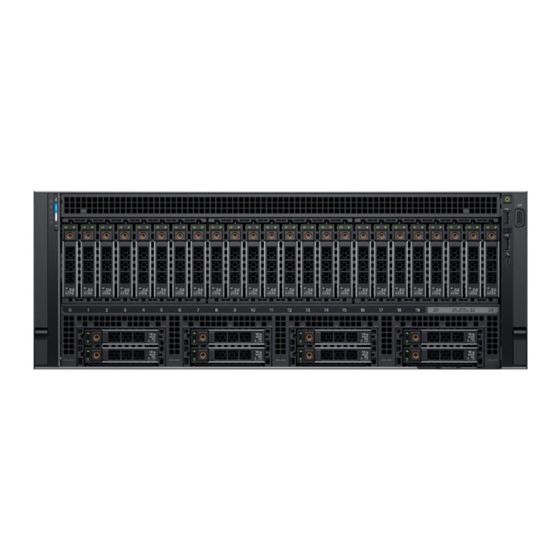
PowerEdge R940xa system overview The PowerEdge R940xa is a 4U rack server that supports up to: • Four Intel Xeon Processor Scalable family processors • 48 DIMM slots • Four AC or DC power supply units with 2+2 redundancy, auto sensing, and autoswitching capability. -
Page 10: Control Panels
When the system needs attention, the LCD backlight turns amber, and displays an error code followed by descriptive text. NOTE: If the system is connected to a power source and an error is detected, the LCD turns amber regardless of whether the system is turned on or off. PowerEdge R940xa system overview... - Page 11 DNS entries are available. Set error Select SEL to view LCD error messages in a format that matches the IPMI description in the SEL. This enables you to match an LCD message with an SEL entry. PowerEdge R940xa system overview...
-
Page 12: Back View Of The System
6. iDRAC9 dedicated port 7. USB 3.0 ports (2) 8. VGA port 9. Serial port 10. Low profile expansion card slots (2) 11. NIC ports (4) NOTE: For more information on the ports and connectors, see Technical specifications. PowerEdge R940xa system overview... -
Page 13: Inside The System
The mini Enterprise Service Tag (EST) is found on the back of the system chassis. This information is used by Dell to route support calls to the appropriate personnel. Figure 7. Locating the information tag of your system 1. Information tag (Top view) 2. Information tag (Bottom view) 3. OpenManage Mobile (OMM) label PowerEdge R940xa system overview... -
Page 14: System Information Label
Information tag. This label will be blank, if you have not opted for secure default access to iDRAC, then the default user name and password are root and calvin. 5. Service Tag System information label PowerEdge R940xa – Front system information label Figure 8. LED behavior PowerEdge R940xa system overview... - Page 15 Figure 9. Configuration and layout Figure 10. Express service tag PowerEdge R940xa system overview...
- Page 16 Figure 11. Icon Legend PowerEdge R940xa – Service information Figure 12. Service Information PowerEdge R940xa system overview...
- Page 17 Figure 13. Rear view configuration Figure 14. Jumper settings PowerEdge R940xa system overview...
- Page 18 Figure 15. Memory information Figure 16. System tasks Figure 17. Cabling overview PowerEdge R940xa system overview...
- Page 19 Figure 18. Electrical overview PowerEdge R940xa system overview...
-
Page 20: Initial System Setup And Configuration
Initial system setup and configuration Setting up your system Perform the following steps to set up your system: Steps 1. Unpack the system. 2. Install the system into the rack. For more information about installing the system into the rack, see the Rail Installation Guide at www.dell.com/poweredgemanuals. -
Page 21: Log In To Idrac
Dell certified VMware ESXi www.dell.com/virtualizationsolutions Installation and How-to videos for supported operating systems on Supported Operating Systems for Dell EMC PowerEdge systems PowerEdge systems Methods to download firmware and drivers You can download the firmware and drivers by using any of the following methods: Table 3. -
Page 22: Downloading Drivers And Firmware
Downloading drivers and firmware Dell EMC recommends that you download and install the latest BIOS, drivers, and systems management firmware on your system. Prerequisites Ensure that you clear the web browser cache before downloading the drivers and firmware. Steps 1. Go to www.dell.com/support/home. -
Page 23: Pre-Operating System Management Applications
Pre-operating system management applications You can manage basic settings and features of a system without booting to the operating system by using the system firmware. Topics: • Options to manage the pre-operating system applications • System Setup • Dell Lifecycle Controller •... -
Page 24: System Bios
Option Description System BIOS Enables you to configure BIOS settings. iDRAC Settings Enables you to configure the iDRAC settings. The iDRAC settings utility is an interface to set up and configure the iDRAC parameters by using UEFI (Unified Extensible Firmware Interface). You can enable or disable various iDRAC parameters by using the iDRAC settings utility. - Page 25 Option Description System Profile Specifies options to change the processor power management settings, memory frequency. Settings System Security Specifies options to configure the system security settings, such as system password, setup password, Trusted Platform Module (TPM) security, and UEFI secure boot. It also manages the power button on the system. Redundant OS Sets the redundant OS info for redundant OS control.
- Page 26 Memory Settings You can use the Memory Settings screen to view all the memory settings and enable or disable specific memory functions, such as system memory testing and node interleaving. View Memory Settings To view the Memory Settings screen, perform the following steps: Steps 1.
- Page 27 Option Description Node Interleaving Specifies if Non-Uniform Memory Architecture (NUMA) is supported. If this field is set to Enabled, memory interleaving is supported if a symmetric memory configuration is installed. If the field is set to Disabled, the system supports NUMA (asymmetric) memory configurations. This option is set to Disabled by default. ADDDC Setting Enables or disables ADDDC Setting feature.
- Page 28 Option Description However, if power-saving considerations outweigh performance, you might want to reduce the frequency of the CPU communication links. If you do this, you should localize memory and I/O accesses to the nearest NUMA node to minimize the impact to system performance. Virtualization Enables or disables the virtualization technology for the processor.
- Page 29 Option Description Option Description Family-Model- Specifies the family, model, and stepping of the processor as defined by Intel. Stepping Brand Specifies the brand name. Level 2 Cache Specifies the total L2 cache. Level 3 Cache Specifies the total L3 cache. Number of Cores Specifies the number of cores per processor.
- Page 30 Option Description Option Description Drive Type Specifies the type of drive attached to the SATA port. NOTE: If no device is installed, it displays Unkown Device. Capacity Specifies the total capacity of the drive. This field is undefined for removable media devices such as optical drives.
- Page 31 View Boot Settings To view the Boot Settings screen, perform the following steps: Steps 1. Turn on, or restart your system. 2. Press F2 immediately after you see the following message: F2 = System Setup NOTE: If your operating system begins to load before you press F2, wait for the system to finish booting, and then restart your system and try again.
- Page 32 Viewing Network Settings To view the Network Settings screen, perform the following steps: Steps 1. Turn on, or restart your system. 2. Press F2 immediately after you see the following message: F2 = System Setup NOTE: If your operating system begins to load before you press F2, wait for the system to finish booting, and then restart your system and try again.
- Page 33 Integrated Devices You can use the Integrated Devices screen to view and configure the settings of all integrated devices including the video controller, integrated RAID controller, and the USB ports. Viewing Integrated Devices To view the Integrated Devices screen, perform the following steps: Steps 1.
- Page 34 Option Description SR-IOV Global Enables or disables the BIOS configuration of Single Root I/O Virtualization (SR-IOV) devices. This option is set to Enable Disabled by default. OS Watchdog If your system stops responding, this watchdog timer aids in the recovery of your operating system. When this Timer option is set to Enabled, the operating system initializes the timer.
- Page 35 Slot Bifurcation About this task The Slot Bifurcation screen details are explained as follows: Slot Bifurcation Allows Platform Default Bifurcation, Auto discovery of Bifurcation and Manual bifurcation Control. The default is set to Platform Default Bifurcation. The slot bifurcation field is accessible when set to Manual bifurcation Control and is grayed out when set to Platform Default Bifurcation or Auto discovery of Bifurcation.
- Page 36 Serial Communication details About this task The Serial Communication screen details are explained as follows: Option Description Serial Selects serial communication devices (Serial Device 1 and Serial Device 2) in BIOS. BIOS console redirection can Communication also be enabled, and the port address can be specified. This option is set to Auto by default. Enables the COM port or Console Redirection options.
- Page 37 System Profile Settings details About this task The System Profile Settings screen details are explained as follows: Option Description System Profile Sets the system profile. If you set the System Profile option to a mode other than Custom, the BIOS automatically sets the rest of the options.
- Page 38 System Security You can use the System Security screen to perform specific functions such as setting the system password, setup password and disabling the power button. Viewing System Security To view the System Security screen, perform the following steps: Steps 1.
- Page 39 Option Description Table 8. TPM 2.0 security information TPM information Description TPM Information Changes the operational state of the TPM. This option is set to No Change by default. TPM Firmware Indicates the firmware version of the TPM. TPM Hierarcy Enable, disable, or clear the storage and endorsement hierarchies.
- Page 40 Option Description Options Description Deployed Mode Deployed Mode is the most secure mode. In Deployed Mode, PK must be installed and the BIOS performs signature verification on programmatic attempts to update policy objects. Deployed Mode restricts the programmatic mode transitions. Secure Boot Policy Summary About this task The Secure Boot Policy Summary screen details are explained as follows:...
- Page 41 Option Description • Internal USB NOTE: RAID configurations and NVMe cards not are included as BIOS does not have the ability to distinguish between individual drives in those configurations. Redundant OS NOTE: This option is disabled if Redundant OS Location is set to None. State When set to Visible, the backup disk is visible to the boot list and OS.
-
Page 42: Idrac Settings Utility
Option Description available only for UEFI boot mode. You cannot set the option to Enabled if UEFI Secure Boot mode is enabled. This option is set to Disabled by default. Dell Wyse Enables or disables the Dell Wyse P25/P45 BIOS Access. This option is set to Enabled by default. P25/P45 BIOS Access Power Cycle... -
Page 43: Boot Manager Main Menu
Boot Manager main menu Menu item Description Continue Normal The system attempts to boot to devices starting with the first item in the boot order. If the boot attempt fails, the Boot system continues with the next item in the boot order until the boot is successful or no more boot options are found. -
Page 44: Installing And Removing System Components
Installing and removing system components CAUTION: Many repairs may only be done by a certified service technician. You should only perform troubleshooting and simple repairs as authorized in your product documentation, or as directed by the online or telephone service and support team. -
Page 45: Before Working Inside Your System
support team. Damage due to servicing that is not authorized by Dell is not covered by your warranty. Read and follow the safety instructions that are shipped with your product. NOTE: It is recommended that you always use an antistatic mat and antistatic strap while working on components inside the system. -
Page 46: Removing The Optional Front Bezel
Removing the optional front bezel Prerequisites Follow the safety guidelines listed in Safety instructions. Steps 1. Unlock the bezel by using the bezel key. 2. Press the release button, and pull the left end of the bezel. 3. Unhook the right end, and remove the bezel. Figure 19. -
Page 47: Drives
When you format a drive, allow enough time for the formatting to complete. Be aware that high-capacity drives can take a long time to format. Drives The PowerEdge R940xa system supports SAS, SATA, Nearline SAS hard drives/SSDs, or NVMe drives. The supported drive and SSD options for the PowerEdge R940xa system are: •... -
Page 48: Installing The Drive Blank
CAUTION: Mixing drive blanks from previous generations of PowerEdge servers is not supported. Steps 1. Press the release button. 2. Slide the drive blank out of the drive slot. Figure 21. Removing a drive blank Next steps Replace the Drive or a drive blank. -
Page 49: Removing A Drive Carrier
Removing a drive carrier Prerequisites 1. Follow the safety guidelines listed in Safety instructions. 2. Follow the procedure listed in Before working inside your system. 3. Using the management software, prepare the drive for removal. If the drive is online, the green activity or fault indicator flashes while the drive is turning off. When the drive indicators are off, the drive is ready for removal. -
Page 50: Removing The Drive From The Drive Carrier
CAUTION: When installing a drive, ensure that the adjacent drives are fully installed. Inserting a drive carrier and attempting to lock its handle next to a partially installed carrier can damage the partially installed carrier's shield spring and make it unusable. NOTE: Ensure that the drive carrier's release handle is in the open position before inserting the carrier into the slot. -
Page 51: Installing The Drive Into The Drive Carrier
Figure 25. Removing the drive from the drive carrier Next steps Replace the drive into the drive carrier. Installing the drive into the drive carrier Prerequisites Remove the front bezel. NOTE: When installing a drive into the drive carrier, ensure that the screws are torqued to 4 in-lbs. Steps 1. -
Page 52: System Cover
Next steps Replace the front bezel. System cover System cover provides security for the entire system and also helps in maintaining proper air flow inside the system. Removing the system cover Prerequisites 1. Follow the safety guidelines listed in Safety instructions. -
Page 53: Installing The System Cover
Installing the system cover Prerequisites 1. Follow the safety guidelines listed in Safety instructions. 2. Ensure that all internal cables are routed correctly and connected, and no tools or extra parts are left inside the system. Steps 1. Place the system cover on the system. 2. -
Page 54: Installing The Support Bar
Steps 1. Loosen the thumb screws on the support bar. 2. Pull the blue release pins inwards. 3. Lift the support bar from of the system. Figure 29. Removing the support bar Next steps Replace the support bar. Installing the support bar Prerequisites 1. -
Page 55: Cooling Fans
Figure 30. Installing the support bar Next steps Follow the procedure listed in After working inside your system. Cooling fans The cooling fans are integrated into the system to dissipate the heat generated by the functioning of the system. These fans provide cooling for the processors, expansion cards, and memory modules. -
Page 56: Installing A Cooling Fan
Figure 31. Removing the cooling fan Next steps Replace the cooling fan. Installing a cooling fan Prerequisites CAUTION: Opening or removing the system cover when the system is on may expose you to a risk of electric shock. Exercise utmost care while removing or installing cooling fans. CAUTION: The cooling fans are hot swappable. -
Page 57: Cooling Fan Assembly
Figure 32. Installing cooling fan Next steps 1. Follow the procedure listed in After working inside your system. Cooling fan assembly The cooling fan assembly houses the array of cooling fans. A failure in the server’s cooling system can result in the server overheating and may lead to damage. -
Page 58: Installing The Cooling Fan Assembly
Figure 33. Removing the cooling fan assembly Next steps Replace the cooling fan assembly. Installing the cooling fan assembly Prerequisites 1. Follow the safety guidelines listed in Safety instructions. 2. Follow the procedure listed in Before working inside your system. CAUTION: Observe the routing of the cable as you remove it from the system. -
Page 59: Optional Usb 3.0 Module
Figure 34. Installing the cooling fan assembly Next steps 1. Follow the procedure listed in After working inside your system. Optional USB 3.0 module An additional USB 3.0 port can be added to the front of the system. The USB 3.0 module cable connects to the internal USB port on the system board. -
Page 60: Installing The Usb 3.0 Module
Slide the USB 3.0 module out of the system. Figure 35. Removing USB 3.0 module Next steps Replace the USB 3.0 module or the USB 3.0 blank. NOTE: The procedure to remove a USB 3.0 blank is similar to the USB 3.0 module. Installing the USB 3.0 module Prerequisites 1. -
Page 61: Optional Optical Drive
Figure 36. Installing the USB 3.0 module NOTE: To locate the connector, see System board connectors. Next steps Replace the cooling fan assembly. Replace the air shrouds. Replace the support bar. Replace the front bezel. 5. Follow the procedure listed in After working inside your system. - Page 62 Steps 1. Press the release tab to release the optical drive. 2. Slide the optical drive out of the system. Figure 37. Removing optical drive Figure 38. Installing optical drive blank Installing and removing system components...
-
Page 63: Installing The Optical Drive
Next steps Replace the optical drive. Installing the optical drive Prerequisites 1. Follow the safety guidelines listed in Safety instructions. 2. Follow the procedure listed in Before working inside your system. Remove the front bezel. Remove the support bar. Remove the air shroud. -
Page 64: Control Panel
Figure 40. Installing the optical drive Next steps 1. Connect the power and data cables to the connector on the optical drive and the connector on the system board. NOTE: Route the cable properly on the side of the system to prevent it from being pinched or crimped. Replace the cooling fan assembly. -
Page 65: Installing The Left Control Panel
Steps 1. Lift the cable latch and disconnect the control panel cable from the system board connector. NOTE: Ensure that you note the routing of the cables as you remove them from the system. 2. Using a Phillips #1 screwdriver, remove the screws that secure cable cover and remove it from the system. 3. -
Page 66: Removing The Right Control Panel
Figure 42. Installing the left control panel Next steps Replace the cooling fan assembly. Replace the air shrouds. Replace the support bar. Replace the front bezel. 5. Follow the procedure listed in After working inside your system. Removing the right control panel Prerequisites 1. -
Page 67: Installing The Right Control Panel
Figure 43. Removing right control panel Next steps Replace the right control panel. Installing the right control panel Prerequisites 1. Follow the safety guidelines listed in Safety instructions. 2. Follow the procedure listed in Before working inside your system. Remove the front bezel. -
Page 68: Air Shroud
Air shroud The air shroud directs the airflow across the entire system. The air shrouds maintain uniform airflow inside the system The PowerEdge R940xa has four air shrouds as mentioned below: NOTE: Ensure that you install or remove the air shrouds in the order mentioned below: 1. - Page 69 Remove the support bar. Steps 1. Press the blue release latches. 2. Lift the air shroud out of the system. Figure 45. Removing the air shroud A Next steps Replace the air shroud Installing the air shroud A Prerequisites 1. Follow the safety guidelines listed in Safety instructions.
-
Page 70: Gpu Shroud
Figure 46. Installing the air shroud A Next steps Replace the support bar. 2. Follow the procedure listed in After working inside your system. GPU shroud Removing the GPU shroud Prerequisites NOTE: The GPU shroud must be removed only when a GPU is installed in the system. 1. - Page 71 Figure 47. Removing the GPU Shroud Next steps Install the GPU. Installing the GPU shroud Prerequisites 1. Follow the safety guidelines listed in Safety instructions. 2. Follow the procedure listed in Before working inside your system. Remove the support bar. Remove the air shroud 5.
-
Page 72: Air Shroud B
Figure 48. Installing the GPU shroud Next steps Replace the air shroud A Replace the support bar 3. Follow the procedure listed in After working inside your system. Air shroud B Removing the air shroud B Prerequisites 1. Follow the safety guidelines listed in Safety instructions. - Page 73 Figure 49. Removing the Air Shroud B Next steps Replace the air shroud Installing the air shroud B Prerequisites 1. Follow the safety guidelines listed in Safety instructions. 2. Follow the procedure listed in Before working inside your system. 3. If applicable, route the cables inside the system along the system wall and secure the cables by using the cable latch. Remove the support bar.
-
Page 74: Air Shroud C
Figure 50. Installing the air shroud B Next steps Replace the NVDIMM-N battery. Replace the air shroud A Replace the support bar 4. Follow the procedure listed in After working inside your system. Air shroud C Removing the Air Shroud C Prerequisites CAUTION: Ensure that the riser 1 cables do not get pinched or crimped while placing the air shroud C. - Page 75 Figure 51. Removing the Air Shroud C Next steps Replace the air shroud Installing the air shroud C Prerequisites 1. Follow the safety guidelines listed in Safety instructions. 2. Follow the procedure listed in Before working inside your system. Remove the support bar.
-
Page 76: Nvdimm-N Battery
Figure 52. Installing the air shroud C Next steps Replace the air shroud B Replace the NVDIMM-N battery. Replace the air shroud A Replace the support bar 5. Follow the procedure listed in After working inside your system. NVDIMM-N battery This section contains information about the removal and installation of the NVDIMM battery from the air shroud. -
Page 77: Installing The Nvdimm-N Battery
Steps 1. Disconnect the battery backup cable, and the NVDIMM connector cable from the NVDIMM-N battery. 2. Using a Phillips #2 screwdriver, loosen the screw securing the NVDIMM-N battery. 3. Lift the NVDIMM-N battery at an angle to disengage it from the slot on the air shroud. 4. -
Page 78: Drive Backplane
Follow the procedure listed in After working inside your system. Drive backplane Depending on your system configuration, the drive backplanes supported in PowerEdge R940xa are listed here: Table 9. Supported backplane options for PowerEdge R940xa system. System Supported backplane options 2.5-inch (x24) SAS/SATA backplane... - Page 79 Figure 55. 2.5-inch (x24) SAS/SATA backplane 1. Slimline SAS cable connector 2. Slimline SAS cable connector 3. Power cable connector 4. Power cable connector 5. Power cable connector 6. Backplane signal connector Figure 56. 2.5-inch (x24) backplane expander 1. Mini SAS hard drive AB 0 2.
-
Page 80: Removing The Drive Backplane
Figure 58. 2.5-inch (x8) SAS/SATA lower backplane 1. Mini SAS hard drive B 1 2. Mini SAS hard drive A 1 3. Power cable connector 4. Backplane signal connector Removing the drive backplane Prerequisites CAUTION: To prevent damage to the drives and backplane, remove the drives from the system before removing the backplane. - Page 81 Figure 59. Removing the backplane expander board 4. Press and hold the blue release tabs, and lift the lower backplane to disengage the slots from the guides on the system. 5. Lift the lower backplane out of the system. Figure 60. Removing the lower backplane Next steps Replace the backplane.
-
Page 82: Installing The Backplane
Installing the backplane Prerequisites 1. Follow the safety guidelines listed in Safety instructions. 2. Follow the procedure listed in Before working inside your system. 3. Disconnect the cables. a. If applicable, disconnect the slimline SAS, I2C, and power cables to the backplane. b. - Page 83 Figure 62. Installing the backplane expander board Next steps 1. Connect the cables. a. If applicable, connect the slimline SAS, I2C, and power cables to the backplane. b. Connect the I2C and power cables to the system board. Replace the cooling fan assembly.
-
Page 84: Cable Routing
Cable routing Figure 63. 8 x 2 CPU GPU Figure 64. 8 x 2 CPU no GPU, 8 x 4 CPU no GPU without front NVMe, 8 x 4 CPU GPU without front NVMe Installing and removing system components... - Page 85 Figure 65. 8 X Chipset SATA Figure 66. 32 x 4 P Single PERC/GPU/NVMe Installing and removing system components...
- Page 86 Figure 67. 32 x 2 P Single PERC/GPU/No-NVMe Figure 68. 32 x 4 P Single PERC/GPU/No-NVMe Installing and removing system components...
-
Page 87: System Memory
Figure 69. 32 x 4 P Single PERC/GPU/NVMe Figure 70. 32 x 2 P Single PERC/No-GPU/NVMe System memory Your system contains 48 memory sockets split into four sets of 12 sockets, one set per processor. Each 12-socket set is organized into six channels. - Page 88 Figure 71. Memory socket locations Memory channels are organized as follows: Table 10. Memory channels Processor Channel 0 Channel 1 Channel 2 Channel 3 Channel 4 Channel 5 Processor 1 Slots A1 and A7 Slots A2 and A8 Slots A3 and A9 Slots A4 and A10 Slots A5 and A11 Slots A6 and A12...
-
Page 89: General Memory Module Installation Guidelines
General memory module installation guidelines To ensure optimal performance of your system, observe the following general guidelines when configuring your system memory. If your system's memory configurations fail to observe these guidelines, your system might not boot, stop responding during memory configuration, or operate with reduced memory. - Page 90 • For systems with four processors, RDIMMs populated on processor 3 and 4 must be identical to the number of RDIMMs populated on processor 1 and 2. • All slots on configurations 3, 6, 9, and 12 can be used, but a maximum of 12 NVDIMM-Ns can be installed in a system. For more information on the supported NVDIMM-N configurations, see the NVDIMM-N User Guide at www.dell.com/poweredgemanuals.
- Page 91 Configuration Description Memory population rules RDIMMs NVDIMM-N Configuration 13 12x 16 GB RDIMMs, 12x Same for all 12x RDIMM Processor1 {A7, 8, 9, 10, 11, 12} NVDIMM-Ns configurations. See Processor2 {B7, 8, 9, 10, 11, 12} Configuration 1. Configuration 14 12x 32 GB RDIMMs, 12x Same for all 12x RDIMM Processor1 {A7, 8, 9, 10, 11, 12}...
-
Page 92: Dcpmm Installation Guidelines
Memory population rules Configuration Description RDIMMs NVDIMM-N Processor3 {C1, 2, 3, 4, 5, 6} Processor4 {D1, 2, 3, 4, 5, 6} Configuration 9 44x 32GB RDIMMs, 4x Processor1 {A1, 2, 3, 4, 5, 6, 7, 8, Processor1 {A11, 12}, NVDIMM-Ns 9, 10}, Processor2 {B11, 12} Processor2 {B1, 2, 3, 4, 5, 6, 7,... - Page 93 Mixing different capacities of RDIMMs and LRDIMMs are not allowed when DCPMM is installed. • DCPMMs of different capacities are not allowed. For more information about the supported DCPMM configurations, see the Dell EMC DCPMM User 's Guide at https://www.dell.com/ support/home/us/en/19/products/server_int/server_int_poweredge.
-
Page 94: Mode-Specific Guidelines
Mode-specific guidelines The configurations allowed depend on the memory mode selected in the System BIOS. Table 15. Memory operating modes Memory Operating Mode Description Optimizer Mode The Optimizer Mode if enabled, the DRAM controllers operate independently in the 64-bit mode and provide optimized memory performance. - Page 95 • Dual processor: Populate the slots in round robin sequence starting with processor 1. NOTE: Processor 1 and processor 2 population should match. • Quad processor: Populate the slots in round robin sequence starting with processor 1. NOTE: Processor 1, processor 2, processor 3, and processor 4 population should match. Table 16.
-
Page 96: Removing A Memory Module
Processor Configuration Memory population Memory population information NOTE: For best performance, 6 DIMMs or 12 DIMMs per processor is recommended. Optimizer population order is not traditional for 16 and 32 DIMMs installations for dual processor. • For 16 DIMMs: A1, A2, A4, A5, B1, B2, B4, B5, C1, C2, C4, C5, D1, D2, D4, D5 •... -
Page 97: Installing The Memory Module
CAUTION: To ensure proper system cooling, memory module blanks must be installed in any memory socket that is not occupied. Remove memory module blanks only if you intend to install memory modules in those sockets. Steps 1. Locate the appropriate memory module socket. CAUTION: Handle each memory module only by the card edges, ensuring not to touch the middle of the memory module or metallic contacts. -
Page 98: Processors And Heat Sinks
CAUTION: Handle each memory module only by the card edges, ensuring not to touch the middle of the memory module or metallic contacts. CAUTION: To prevent damage to the memory module or the memory module socket during installation, do not bend or flex the memory module. -
Page 99: Removing A Processor And Heat Sink Module
Removing a processor and heat sink module Prerequisites WARNING: The heat sink may be hot to touch for some time after the system is powered down. Allow the heat sink to cool before removing it. 1. Follow the safety guidelines listed in Safety instructions. -
Page 100: Removing The Processor From The Processor And Heat Sink Module
Figure 75. Removing a PHM from CPU 3 or 4 Next steps Replace the processor and heat sink module. Removing the processor from the processor and heat sink module Prerequisites WARNING: The heat sink may be hot to touch for some time after the system has been powered down. Allow the heat sink to cool before removing it. - Page 101 Figure 76. Loosening the processor bracket from CPU 1/2 Figure 77. Loosening the processor bracket from CPU 3/4 3. Lift the bracket and the processor from the heat sink, and place the processor connector side down on the processor tray. 4.
-
Page 102: Installing The Processor On The Processor And Heat Sink Module
Figure 78. Removing the processor bracket Next steps Install the processor or the processor dust cover. Installing the processor on the processor and heat sink module Prerequisites WARNING: The heat sink may be hot to touch for some time after the system has been powered down. Allow the heat sink to cool before removing it. - Page 103 Figure 79. Installing the processor bracket 3. If you are using an existing heat sink, remove the thermal grease from the heat sink by using a clean lint-free cloth. 4. Use the thermal grease syringe included with your processor kit to apply the grease in a quadrilateral design on the top of the processor.
-
Page 104: Installing A Processor And Heat Sink Module
• Ensure that the pin 1 indicator on the heat sink is aligned with the pin 1 indicator on the bracket before placing the heat sink onto the processor and bracket. Next steps Replace the processor and heat sink module. 2. - Page 105 Figure 81. Installing the PHM on CPU 1 or 2 Figure 82. Installing the PHM on CPU 3 or 4 Next steps Replace the cooling fan assembly. Replace the air shrouds. Replace the support bar Installing and removing system components...
-
Page 106: Expansion Cards And Expansion Card Risers
However, if a F1/F2 pause occurs and an error message is displayed. Expansion card installation guidelines The PowerEdge R940xa system supports up to 12 PCI express (PCIe) generation 3 expansion cards, that can be installed on the system board using expansion card risers. - Page 107 Number of NVMe Riser size Slot size Slot Available Height Length processors quantity slots Non-GPU/ X8 PCIe Riser 1 Single wide X8 PCIe Riser 2 10,11 FPGA NOTE: Use double-wide accelerator capable for installation or removal of Xilinx card. Table 18. Riser configuration (X16PCIe Riser 1+X16 PCIe Riser 2) in a dual processor configuration Card Type Slot Priority Maximum number of Cards...
- Page 108 Card Type Slot Priority Maximum number of Cards Qlogic 25G NICs 11,4 Qlogic 25G NICs Emulex FC16 HBA 11,4 Emulex FC16 HBA Qlogic FC16 HBA 11,4 Qlogic FC16 HBA Broadcom 10Gb NICs Broadcom 10Gb NICs 11,4 INTEL 10Gb NICs INTEL 10Gb NICs 11,4 Mellanox 10Gb NICs Mellanox 10Gb NICs...
- Page 109 Card Type Slot Priority Maximum number of Cards Dell design BOSS 3,4,10,11 Dell design BOSS Dell design External RAID Dell design External RAID 3,4,10,11 Mellanox Infiniband HCA FDR INTEL 40Gb NICs 3,4,10,11 INTEL 40Gb NICs Mellanox 40G NICs Mellanox 40G NICs 3,4,10,11 Emulex FC32 HBA 3,4,10,11...
- Page 110 Card Type Slot Priority Maximum number of Cards Qlogic FC8 HBA 3,4,10,11 Broadcom 1Gb NICs 3,4,10,11 Broadcom 1Gb NICs INTEL 1Gb NICs INTEL 1Gb NICs 3,4,10,11 Dell design Non-RAID Dell design Non-RAID 3,4,10,11 Dell design NVMe PCIe SSD 3,4,10,11,6,7 INTEL rNDC Integrated Slot Broadcom rNDC Integrated Slot...
- Page 111 Card Type Slot Priority Maximum number of Cards Qlogic FC32 HBA Broadcom 25G NICs Broadcom 25G NICs 5,12,9,11,2,4 INTEL 25Gb NICs 5,12,9,11,2,4 INTEL 25Gb NICs Mellanox 25G NICs 5,12,9,11,2,4 Mellanox 25G NICs Qlogic 25G NICs 5,12,9,11,2,4 Qlogic 25G NICs Emulex FC16 HBA 5,12,9,11,2,4 Emulex FC16 HBA Qlogic FC16 HBA...
- Page 112 Table 21. Riser configuration (X8PCIe Riser 1+X8 PCIe Riser 2) in a quad processor configuration Card Type Slot Priority Maximum number of Cards Dell design PERC10 Intel FPGA 1,2,3,4,8,9,10,11 Mellanox Infiniband HCA EDR Mellanox 100G NICs INTEL Omni-Path HFI Dell design BOSS 1,2,3,4,5,8,9,10,11,12 Dell design BOSS Dell design External RAID...
- Page 113 Card Type Slot Priority Maximum number of Cards Qlogic 10Gb NICs Solarflare 10Gb NICs 1,2,3,4,5,8,9,10,11,12 Solarflare 10Gb NICs Emulex FC8 HBA Emulex FC8 HBA 1,2,3,4,5,8,9,10,11,12 Qlogic FC8 HBA Qlogic FC8 HBA 1,2,3,4,5,8,9,10,11,12 Broadcom 1Gb NICs 1,2,3,4,5,8,9,10,11,12 Broadcom 1Gb NICs INTEL 1Gb NICs INTEL 1Gb NICs 1,2,3,4,5,8,9,10,11,12 Dell design Non-RAID...
- Page 114 Card Type Slot Priority Maximum number of Cards Dell design External RAID 9,11,2,4 Mellanox Infiniband HCA FDR INTEL 40Gb NICs 9,11,2,4 INTEL 40Gb NICs Mellanox 40G NICs Mellanox 40G NICs 9,11,2,4 Emulex FC32 HBA 9,11,2,4 Emulex FC32 HBA Qlogic FC32 HBA 9,11,2,4 Qlogic FC32 HBA Broadcom 25G NICs...
- Page 115 Card Type Slot Priority Maximum number of Cards INTEL 1Gb NICs INTEL 1Gb NICs 9,11,2,4 Dell design Non-RAID Dell design Non-RAID 9,11,2,4 Dell design NVMe PCIe SSD 6,7,9,11,2,4 INTEL rNDC Integrated Slot Broadcom rNDC Integrated Slot Mellanox rNDC Integrated Slot Qlogic rNDC Integrated Slot Table 23.
-
Page 116: Removing The Expansion Card Riser
Card Type Slot Priority Maximum number of Cards Emulex FC16 HBA Qlogic FC16 HBA 1,2,3,4,8,9,10,11 Qlogic FC16 HBA Broadcom 10Gb NICs Broadcom 10Gb NICs 1,2,3,4,8,9,10,11 INTEL 10Gb NICs INTEL 10Gb NICs 1,2,3,4,8,9,10,11 Mellanox 10Gb NICs Mellanox 10Gb NICs 1,2,3,4,8,9,10,11 Qlogic 10Gb NICs 1,2,3,4,8,9,10,11 Qlogic 10Gb NICs Solarflare 10Gb NICs... - Page 117 Remove the air shrouds. Steps 1. Disconnect the cables from the Power Interposer Board (PIB), system board, and the backplane. NOTE: Ensure that you remove the cables that are secured using the cable securing bracket routed along the chassis wall. NOTE: Remove the drive cable and the system board cables.
-
Page 118: Installing The Expansion Card Riser
Figure 85. Removing the X8 PCIe Riser 2 NOTE: You must install a filler bracket over an empty expansion card slot to maintain Federal Communications Commission (FCC) certification of the system. The brackets also keep dust and dirt out of the system and aid in proper cooling and airflow inside the system. - Page 119 Figure 86. Installing the X8 PCIe Riser 1 Installing and removing system components...
-
Page 120: Removing The Expansion Card From The Riser
Figure 87. Installing the X8 PCIe Riser 2 Next steps Replace the air shrouds. Replace the support bar. 3. Follow the procedure listed in After working inside your system. Removing the expansion card from the riser Prerequisites 1. Follow the safety guidelines listed in Safety instructions. -
Page 121: Installing The Expansion Card In The Riser
Figure 88. Removing the expansion card from the riser Next steps 1. Install a filler bracket if you are not going to replace the expansion card. NOTE: You must install a filler bracket over an empty expansion card slot to maintain Federal Communications Commission (FCC) certification of the system. -
Page 122: Removing The Expansion Card From The System Board
Figure 89. Installing the expansion card riser Next steps Replace the expansion card riser. Replace the air shrouds. Replace the support bar 4. Follow the procedure listed in After working inside your system. Removing the expansion card from the system board Prerequisites 1. - Page 123 Figure 90. Removing the Expansion card Figure 91. Installing the filler bracket from a riser Next steps 1. Install a filler bracket if you are not going to replace the expansion card. Installing and removing system components...
-
Page 124: Installing The Expansion Card On The System Board
NOTE: Store the filler bracket for future use. Filler brackets must be installed in empty expansion card slots to maintain Federal Communications Commission (FCC) certification of the system. The brackets also keep dust and dirt out of the system and aid in proper cooling and airflow inside the system. Replace the expansion card riser. -
Page 125: Gpu Card Installation Guidelines
Figure 93. Installing the expansion card 4. Press the expansion card firmly until the card is fully seated. 5. Push the blue expansion card retention latch until the latch snaps into place. 6. Disconnect the cables from the Power Interposer Board (PIB), system board, and the backplane. NOTE: Ensure that you remove the cables that are secured using the cable securing bracket routed along the chassis wall. -
Page 126: Removing The Gpu
• 2x4 pin power connection for single double width GPU • 2x3 pin and 2x4 pin power connection for single double width GPU Removing the GPU Prerequisites 1. Follow the safety guidelines listed in Safety instructions. 2. Follow the procedure listed in Before working inside your system. - Page 127 Figure 94. Removing the GPU 10. If you are removing the GPU permanently, install a filler bracket. NOTE: You must install a filler bracket over an empty expansion card slot to maintain Federal Communications Commission (FCC) certification of the system. The brackets also keep dust and dirt out of the system and aid in proper cooling and airflow inside the system.
-
Page 128: Installing The Gpu
Figure 95. Installing the GPU blank 14. Close the cover. 15. Close the card retention latch by pushing the latch down until the latch snaps into place. Next steps Replace the GPU shroud. Installing the GPU Prerequisites NOTE: The GPU card can be installed only in a X16 PCIe riser configuration. NOTE: The GPU shroud must be removed only when a GPU is installed in the system. - Page 129 NOTE: For instructions, see the documentation accompanying the card. 2. Press and slide the release button upward to lift the cover. 3. Open the card retention latch. 4. Remove the filler bracket from the expansion card holder. NOTE: Store the filler bracket for future use. Filler brackets must be installed in empty expansion card slots to maintain Federal Communications Commission (FCC) certification of the system.
-
Page 130: M.2 Ssd Module
Figure 97. Installing the GPU Next steps Replace the expansion card riser. 2. Connect the GPU power cable, system board slimline cable, and the riser power cable. Replace the air shrouds Replace the support bar. 5. Follow the procedure listed in After working inside your system. -
Page 131: Installing The M.2 Boss Module
2. Pull the M.2 BOSS module from the BOSS card. Figure 98. Removing the M.2 BOSS module Next steps Replace the M.2 BOSS module. Installing the M.2 BOSS module Prerequisites 1. Follow the safety guidelines listed in Safety instructions. Remove the support bar. -
Page 132: Optional Idsdm Or Vflash Module
Figure 99. Installing the M.2 BOSS module Next steps 1. Replace the BOSS card. NOTE: Replacing the BOSS card is similar to the procedure for installing an expansion card. Replace the expansion card riser. Replace the air shrouds. Replace the support bar. -
Page 133: Installing The Microsd Card
Figure 100. Removing the MicroSD card Next steps Replace the MicroSD card. Installing the MicroSD card Prerequisites 1. Follow the safety guidelines listed in Safety instructions. 2. Follow the procedure listed in Before working inside your system. Remove the support bar. -
Page 134: Removing The Idsdm Or Vflash Module
Removing the IDSDM or vFlash module Prerequisites 1. Follow the safety guidelines listed in Safety instructions. 2. Follow the procedure listed in Before working inside your system. Remove the support bar. Remove the air shrouds. Remove the expansion card riser. Remove the MicroSD cards, if you are replacing the IDSDM or vFlash module. -
Page 135: Network Daughter Card
Remove the support bar. Remove the air shrouds. Remove the expansion card riser. Remove the MicroSD cards, if you are replacing the IDSDM or vFlash module. NOTE: Temporarily label each MicroSD card with its corresponding slot number after removal. Steps 1. -
Page 136: Installing The Network Daughter Card
Remove the air shrouds. Remove the expansion card riser Steps 1. Using a Phillips #2 screwdriver, loosen the captive screws that secure the network daughter card (NDC) to the system board. 2. Hold the NDC by the edges, and lift to remove it from the connector on the system board. 3. -
Page 137: System Battery
Figure 104. Installing the network daughter card Next steps Replace the expansion card riser. Replace the air shrouds Replace the support bar. 4. Follow the procedure listed in After working inside your system. System battery The system battery is used for low-level system functions such as powering the real-time and date settings of the system. Replacing the system battery Prerequisites WARNING:... -
Page 138: Optional Internal Usb Memory Key
Figure 105. Removing the system battery 3. To install a new system battery, hold the battery with the positive side facing up and slide it under the securing tabs. 4. Press the battery into the connector until it snaps into place. Figure 106. -
Page 139: Power Supply Units
3. Insert the replacement USB memory key into the USB port. Next steps Install the air shrouds. 2. Follow the procedure listed in after working inside your system. 3. While booting, press F2 to enter System Setup and verify that the system detects the USB memory key. Power supply units The power supply unit (PSU) is an internal hardware component which supplies power to the components in the system. -
Page 140: Installing The Power Supply Unit Blank
Figure 107. Removing a power supply unit blank Next steps Replace the PSU or the blank. Installing the power supply unit blank Prerequisites 1. Follow the safety guidelines listed in Safety instructions. 2. Install the power supply unit (PSU) blank in the available PSU bay. Steps Align the PSU blank with the PSU slot and push it into the PSU slot until it clicks into place. -
Page 141: Installing The Power Supply Unit
Figure 109. Removing a power supply unit Next steps Replace the PSU or the blank. Installing the power supply unit Prerequisites 1. Follow the safety guidelines listed in Safety instructions. 2. For systems that support redundant PSU, ensure that both the PSUs are of the same type and have the same maximum output power. -
Page 142: Wiring Instructions For A Dc Power Supply Unit
Next steps 1. If you have removed the strain relief bar and bracket, replace them. For information about the strain relief bar and bracket, see the Rail Installation Guide at Dell.com/poweredgemanuals. 2. Connect the power cable to the PSU, and plug the cable into a power outlet. CAUTION: When connecting the power cable to the PSU, secure the cable to the PSU with the strap. -
Page 143: Power Interposer Board
Power interposer board Removing the power interposer board Prerequisites 1. Follow the safety guidelines listed in Safety instructions. 2. Follow the procedure listed in Before working inside your system. Remove the support bar. Remove the air shrouds. Remove the power supply units. -
Page 144: Trusted Platform Module
Remove the support bar. Remove the air shrouds. Remove the power supply units. Remove the expansion card risers NOTE: Observe the routing of the cable as you remove it from the system. Route the cable properly when you replace it to prevent the cable from being pinched or crimped. Steps 1. -
Page 145: Upgrading The Trusted Platform Module
Upgrading the Trusted Platform Module Prerequisites NOTE: • Ensure that your operating system supports the version of the TPM module being installed. • Ensure that you download and install the latest BIOS firmware on your system. • Ensure that the BIOS is configured to enable UEFI boot mode. About this task CAUTION: Once the TPM plug-in module is installed, it is cryptographically bound to that specific system board. -
Page 146: Initializing Tpm For Bitlocker Users
5. Run the system memory test in system diagnostics. Initializing TPM for BitLocker users Steps 1. Initialize the TPM. For more information, see initializing the TPM for Intel TXT users. 2. The TPM Status changes to Enabled, Activated. Initializing the TPM 1.2 for TXT users Steps 1. -
Page 147: Removing The System Board
Removing the System Board Prerequisites CAUTION: If you are using the Trusted Platform Module (TPM) with an encryption key, you may be prompted to create a recovery key during program or System Setup. Be sure to create and safely store this recovery key. If you replace this system board, you must supply the recovery key when you restart your system or program before you can access the encrypted data on your drives. -
Page 148: Installing The System Board
Figure 114. Removing the system board Next steps Install the system board. Installing the system board Prerequisites 1. Follow the safety guidelines listed in Safety instructions. 2. Follow the procedure listed in Before working inside your system. Steps 1. Unpack the replacement system board assembly. CAUTION: Do not lift the system board by holding a memory module, processor, or other components. - Page 149 Figure 115. Installing the system board Next steps 1. Replace the following: Trusted platform module NOTE: The TPM Module must be replaced only while installing new system board. NOTE: The TPM plug-in module is attached to the system board and cannot be removed. A replacement TPM plug-in module is provided for all system board replacements where a TPM plug-in module was installed.
-
Page 150: Restore The Service Tag Using Easy Restore
d. Re-enable the Trusted Platform Module (TPM). For more information, see Upgrading the Trusted Platform Module (TPM). 7. Import your new or existing iDRAC Enterprise license. For more information, see iDRAC User's Guide, at www.dell.com/idracmanuals. Restore the service tag using Easy Restore The Easy Restore feature allows you to restore your Service Tag, iDRAC license, UEFI configuration, and the system configuration data after replacing the system board. -
Page 151: Jumpers And Connectors
Jumpers and connectors This topic provides specific information about the jumpers. It also provides some basic information about jumpers and switches and describes the connectors on the various boards in the system. Jumpers on the system board help to disable the system and setup passwords. -
Page 152: System Board Connectors
System board connectors Figure 116. System board connectors Table 24. System board connectors Item Connector Description D7, D1, D8, D2, D9, D3 Memory module sockets for CPU 4 DIMMs — Channels 0/1/2 J_ODD Optical drive power connector CPU4 CPU 4 processor and heat sink module socket—with dust cover J_BP_PWR0 Backplane B power connector Jumpers and connectors... - Page 153 Item Connector Description J_BP_SIG1 Backplane B signal connector (rear) D6, D12, D5, D11, D4, D10 Memory module sockets for CPU 4 DIMMs — Channels 3/4/5 C7, C1, C8, C2, C9, C3 Memory module sockets for CPU 3 DIMMs — Channels 0/1/2 J_FAN4U_4 Cooling fan 4 connector CPU3...
-
Page 154: System Board Jumper Settings
Item Connector Description SATA C connector—Optical drive SATA connector J_SATA_3 A3, A9, A2, A8, A1, A7 Memory module sockets for CPU 1 DIMMs — Channels 0/1/2 A10, A4, A11, A5, A12, A6 Memory module sockets for CPU 1 DIMMs — Channels 3/4/5 CPU1 CPU 1 processor and heat sink module socket—with dust cover SATA D... - Page 155 The existing passwords are not disabled (erased) until the system boots with the jumper on pins 2 and 4. However, before you assign a new system and/or setup password, you must move the jumper back to pins 4 and 6. NOTE: If you assign a new system and/or setup password with the jumper on pins 2 and 4, the system disables the new password(s) the next time it boots.
-
Page 156: Technical Specifications
Technical specifications The technical and environmental specifications of your system are outlined in this section. Topics: • System dimensions • Chassis weight • Processor specifications • Supported operating systems • PSU specifications • System battery specifications • PCIe riser and slots •... -
Page 157: Chassis Weight
Table 27. Chassis weight System Maximum weight (with all drives) PowerEdge R940xa (2.5 x 32 + X16 PCIe Riser 1/X16 PCIe Riser 2 riser with 4 DW GPU + 2 full 56.0 Kg (111.75 lb) height, half length PCIE cards) Processor specifications The PowerEdge R940xa system supports two or four Intel Xeon Processor Scalable Family (Skylake-EP) Gold and Platinum processors. -
Page 158: Supported Operating Systems
Citrix Xen Server For more information on the specific versions and additions, see https://www.dell.com/support/home/Drivers/SupportedOS/ poweredge-r940xa. PSU specifications The PowerEdge R940xa system supports up to four AC or DC power supply units (PSUs). Table 28. PSU specifications Class Heat Frequenc Voltage... -
Page 159: System Battery Specifications
PCIe riser and slots The PowerEdge R940xa system supports up to twelve PCI express (PCIe) generation 3 expansion cards that can be installed on the system board and expansion card risers. The following table provides detailed information about the expansion card riser specifications: Table 29. -
Page 160: Storage Controller Specifications
External storage controller cards: 12 Gbps SAS HBA. Drive specifications Drives The PowerEdge R940xa system supports SAS, SATA, Nearline SAS hard drives/SSDs, or NVMe drives. The supported drive and SSD options for the PowerEdge R940xa system are: • 8 drives system - Up to eight 2.5 inch (SAS, SATA or Nearline SAS) front accessible drives in slots 0 through 7. -
Page 161: Optical Drives
Two USB 3.0-compliant ports on the back of the system NIC ports The PowerEdge R940xa system supports up to four Network Interface Controller (NIC) ports that are integrated on the network daughter card (NDC), and are available in the following configurations: •... -
Page 162: Vga Ports
VGA ports The Video Graphic Array (VGA) port enables you to connect the system to a VGA display. The PowerEdge R940xa system supports two 15-pin VGA ports on the front and back panels. Serial connector The PowerEdge R940xa system supports one serial connector on the back panel, which is a 9-pin connector, Data Terminal Equipment (DTE), 16550-compliant. -
Page 163: Standard Operating Temperature
Table 33. Temperature specifications Temperature Specifications Storage –40°C to 65°C (–40°F to 149°F) Continuous operation (for altitude less than 950 10°C to 35°C (50°F to 95°F) with no direct sunlight on the equipment. m or 3117 ft) Maximum temperature gradient (operating and 20°C/h (68°F/h) storage) Table 34. -
Page 164: Thermal And Acoustics
BIOS setup screen. For more information, see the Dell EMC PowerEdge system Installation and Service Manual on Dell.com/Support/ Manuals and “Advanced Thermal Control: Optimizing across Environments and Power Goals” on Dell.com. - Page 165 Processors Number of Ambient Number of Fresh air Up to 304W Up to 304W Processors Processor/ temperatur Fan type Shroud drives support processor processor GPUs (CPU 1/2) (CPU 3/4) 150W_8C Processor No GPU /4 32x2.5-inch, C40E45 Non-support Six standard 4U height Install the air TDP <= w/o NVMe...
- Page 166 Heat sink Number Number Processo Number DIMM Up to 205W Up to 205W of hard Risers Shroud r/DIMM processo of GPUs type blank blank processor processor drives blank (CPU 1/2) (CPU 3/4) 8 x 2.5 inch SAS/ (L-shape) SATA 24 x 2.5 8 PCIe inch SAS/ (max...
-
Page 167: Particulate And Gaseous Contamination Specifications
Ambient temperature limitations The following table lists configurations that require ambient temperature less than 30°C: NOTE: The ambient temperature limit must be adhered to ensure proper cooling and to avoid excess CPU throttling, which may impact system performance. Table 42. Configuration-based ambient temperature restrictions System Backplane CPU Thermal... -
Page 168: System Diagnostics And Indicator Codes
System diagnostics and indicator codes The diagnostic indicators on the system front panel display system status during system startup. Topics: • Status LED indicators • System health and system ID indicator codes • iDRAC Quick Sync 2 indicator codes • iDRAC Direct LED indicator codes •... -
Page 169: System Health And System Id Indicator Codes
System health and system ID indicator codes The system health and system ID indicator is located on the left control panel of your system. Figure 118. System health and system ID indicators Table 46. System health and system ID indicator codes Indicator code Description Solid blue Indicates that the system is turned on, system is healthy, and system ID mode is not active. -
Page 170: Idrac Direct Led Indicator Codes
Indicator code Description Corrective action Solid amber Indicates that the system is in fail-safe mode. Restart the system. If the problem persists, see the Getting help section. Blinking amber Indicates that the iDRAC Quick Sync 2 Restart the system. If the problem persists, see the Getting help hardware is not responding properly. -
Page 171: Power Supply Unit Indicator Codes
Power supply unit indicator codes AC power supply units (PSUs) have an illuminated translucent handle that serves as an indicator. The DC PSUs have an LED that serves as an indicator. For more information on the PSU specifications, see Technical Specifications. -
Page 172: Drive Indicator Codes
Drive indicator codes The LEDs on the drive carrier indicates the state of each drive. Each drive carrier in your system has two LEDs: an activity LED (green) and a status LED (bicolor, green/amber). The activity LED flashes whenever the drive is accessed. Figure 122. - Page 173 • Run tests automatically or in an interactive mode • Repeat tests • Display or save test results • Run thorough tests to introduce additional test options to provide extra information about the failed device(s) • View status messages that inform you if tests are completed successfully •...
-
Page 174: Getting Help
The Contact Technical Support page is displayed with details to call, chat, or e-mail the Dell Global Technical Support team. Documentation feedback You can rate the documentation or write your feedback on any of our Dell EMC documentation pages and click Send Feedback to send your feedback. -
Page 175: Quick Resource Locator For Poweredge R940Xa System
Receiving automated support with SupportAssist Dell EMC SupportAssist is an optional Dell EMC Services offering that automates technical support for your Dell EMC server, storage, and networking devices. By installing and setting up a SupportAssist application in your IT environment, you can receive the following benefits: •... - Page 176 To view the document that is listed in the documentation resources table: • From the Dell EMC support site: 1. Click the documentation link that is provided in the Location column in the table. 2. Click the required product or product version.
- Page 177 Dell OpenManage Enterprise, see OpenManage Enterprise the Dell OpenManage Enterprise User’s Guide. For information about installing and using Dell www.dell.com/serviceabilitytools SupportAssist, see the Dell EMC SupportAssist Enterprise User’s Guide. For information about partner programs enterprise www.dell.com/openmanagemanuals systems management, see the OpenManage Connections Enterprise Systems Management documents.
Need help?
Do you have a question about the PowerEdge R940xa and is the answer not in the manual?
Questions and answers