Dell EMC PowerEdge R840 Installation And Service Manual
Hide thumbs
Also See for PowerEdge R840:
- Technical manual (60 pages) ,
- Technical specifications (44 pages)
Table of Contents
Advertisement
Quick Links
Download this manual
See also:
Technical Manual
Advertisement
Table of Contents

Subscribe to Our Youtube Channel
Related Manuals for Dell EMC PowerEdge R840


Summary of Contents for Dell EMC PowerEdge R840
- Page 1 Dell EMC PowerEdge R840 Installation and Service Manual Regulatory Model: E49S Series Regulatory Type: E49S001...
- Page 2 Notes, cautions, and warnings NOTE: A NOTE indicates important information that helps you make better use of your product. CAUTION: A CAUTION indicates either potential damage to hardware or loss of data and tells you how to avoid the problem. WARNING: A WARNING indicates a potential for property damage, personal injury, or death.
-
Page 3: Table Of Contents
Contents 1 About this document............................8 2 PowerEdge R840 system overview........................9 Front view of the system..............................9 Control panels................................10 LCD panel..................................11 Back view of the system..............................13 Inside the system................................14 Locating the Service Tag of your system........................16 3 Initial system setup and configuration...................... - Page 4 Installing the front bezel............................43 System cover..................................44 Removing the system cover............................. 44 Installing system cover.............................. 45 Air shroud..................................46 Removing the non-GPU air shroud..........................46 Installing the non-GPU air shroud..........................47 Removing the GPU air shroud..........................48 Installing the GPU air shroud............................50 Cooling fan assembly................................51 Removing the cooling fan assembly.........................
- Page 5 Installing a GPU................................91 Optional M.2 SSD module...............................92 Removing the M.2 SSD module..........................92 Installing the M.2 SSD module..........................93 Processors and heat sinks.............................. 94 Removing a processor and heat sink module......................95 Removing the processor from the processor and heat sink module..............96 Installing the processor into a processor and heat sink module................98 Installing a processor and heat sink module......................101 Optional IDSDM or vFlash module..........................
- Page 6 Restoring Service Tag using Easy Restore........................136 Manually updating Service Tag..........................136 Trusted Platform Module............................... 137 Upgrading Trusted Platform Module........................137 Initializing TPM for BitLocker users........................138 Initializing the TPM 1.2 for TXT users........................138 Control panel................................... 138 Removing left control panel............................ 138 Installing left control panel............................139 Removing right control panel..........................
- Page 7 Using system diagnostics.............................. 169 Dell Embedded System Diagnostics........................169 9 Getting help............................... 170 Contacting Dell................................170 Documentation feedback...............................170 Accessing system information by using QRL......................170 Receiving automated support with SupportAssist .....................171 Quick Resource Locator for PowerEdge R840 system....................171 10 Documentation resources..........................172 Contents...
-
Page 8: About This Document
About this document This document provides an overview about the system, information about installing and replacing components, technical specifications, diagnostic tools, and guidelines to be followed while installing certain components. About this document... -
Page 9: Poweredge R840 System Overview
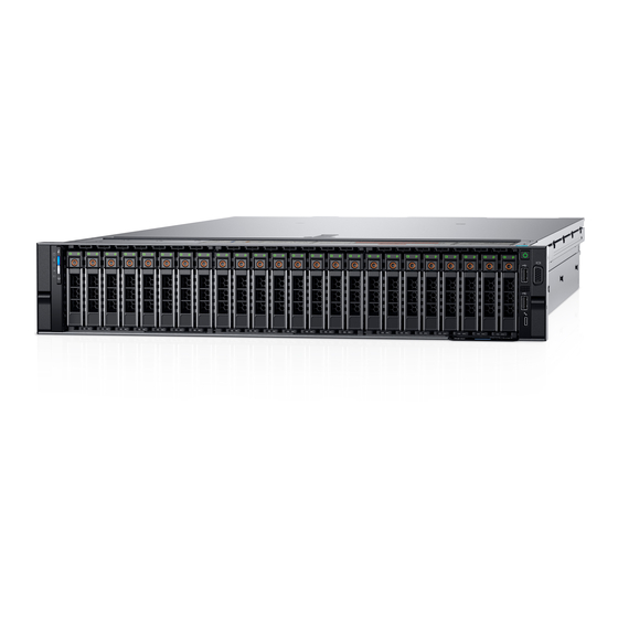
PowerEdge R840 system overview The PowerEdge R840 is a 2U server that supports up to: • Four Intel Xeon Processor Scalable family (Skylake-EP) processors • 48 DIMM slots • Two AC or DC power supply units • 26 SAS, SATA, Nearline SAS hard drives or SSDs including two rear accessible drives, and up to 24 NVMe drives. -
Page 10: Control Panels
Quick Sync 2 feature allows you to manage your system using mobile devices. This feature is only available on certain configurations. For more information about the feature, see the Integrated Dell Remote Access Controller User's Guide at Dell.com/ idracmanuals. PowerEdge R840 system overview... -
Page 11: Lcd Panel
If the LCD panel stops responding, remove the bezel and reinstall it. If the problem persists, see Getting help. • The LCD backlight remains off if LCD messaging is turned off using the iDRAC utility, the LCD panel, or other tools. PowerEdge R840 system overview... - Page 12 DNS entries are available. Set error Select SEL to view LCD error messages in a format that matches the IPMI description in the SEL. This enables you to match an LCD message with an SEL entry. PowerEdge R840 system overview...
-
Page 13: Back View Of The System
Half-height PCIe expansion card slots (Slot 3 and 4) Full-height PCIe expansion card slots (Slot 5 and 6) Power supply units (2) System identification button iDRAC9 dedicated port USB 3.0 ports (2) VGA port Serial port NIC ports (4) Rear handle PowerEdge R840 system overview... -
Page 14: Inside The System
For more information about the ports and connectors, see the Technical Specifications section. Inside the system NOTE: Components that are hot swappable have orange touch points and the components that are not hot swappable have blue touch points. PowerEdge R840 system overview... - Page 15 Figure 8. Inside the system without rear drive cage Drive backplane SAS Expander board Cooling fans (6) System board Full-height expansion card Riser 2 Full-height expansion card Riser 1 Intrusion switch PowerEdge R840 system overview...
-
Page 16: Locating The Service Tag Of Your System
Enterprise Service Tag (EST) is found on the back of the system. This information is used by Dell to route support calls to the appropriate personnel. Figure 10. Locating Service Tag of your system Information tag (top view) Information tag (bottom view) OpenManage Mobile (OMM) label (optional) PowerEdge R840 system overview... - Page 17 If you have opted for secure default access to iDRAC, the iDRAC secure default password is available on the back of the system Information tag. This section of label will be blank, if you have not opted for secure default access to iDRAC, then the default user name and password are root and calvin. Service Tag PowerEdge R840 system overview...
-
Page 18: Initial System Setup And Configuration
Initial system setup and configuration Setting up your system Complete the following steps to set up your system: Unpack the system. Install the system into the rack. For more information about installing the system into the rack, see the Rail Installation Guide at Dell.com/poweredgemanuals. -
Page 19: Log In To Idrac
Interfaces Document/Section iDRAC Direct and See Dell Integrated Dell Remote Access Controller User's Guide at Dell.com/idracmanuals Quick Sync 2 (optional) NOTE: To access iDRAC, ensure that you connect the ethernet cable to the dedicated NIC port. You can also access iDRAC through the shared LOM mode, if you have opted for a system that has the shared LOM mode enabled. -
Page 20: Downloading Drivers And Firmware
Table 3. Firmware and drivers Methods Location From the Dell Support site Dell.com/support/home Using Dell Remote Access Controller Lifecycle Controller (iDRAC Dell.com/idracmanuals with LC) Using Dell Repository Manager (DRM) Dell.com/openmanagemanuals Using Dell OpenManage Essentials (OME) Dell.com/openmanagemanuals Using Dell Server Update Utility (SUU) Dell.com/openmanagemanuals Using Dell OpenManage Deployment Toolkit (DTK) Dell.com/openmanagemanuals... -
Page 21: Pre-Operating System Management Applications
Pre-operating system management applications You can manage basic settings and features of a system without booting to the operating system by using the system firmware. Topics: • Options to manage the pre-operating system applications • System Setup • Dell Lifecycle Controller •... -
Page 22: System Bios
Option Description utility. For more information about this utility, see Integrated Dell Remote Access Controller User’s Guide at Dell.com/idracmanuals. Device Settings Enables you to configure device settings such as network cards or storage controllers. System BIOS You can use the System BIOS screen to edit specific functions such as boot order, system password, setup password, set the SATA and PCIe NVMeRAID mode, and enable or disable USB ports. - Page 23 Option Description UEFI Compliance Specifies the UEFI compliance level of the system firmware. Version Memory Settings You can use the Memory Settings screen to view all the memory settings and enable or disable specific memory functions, such as system memory testing and node interleaving. Viewing Memory Settings To view the Memory Settings screen, perform the following steps: Turn on, or restart your system.
- Page 24 Option Description Node Interleaving Specifies if Non-Uniform Memory Architecture (NUMA) is supported. If this field is set to Enabled, memory interleaving is supported if a symmetric memory configuration is installed. If the field is set to Disabled, the system supports NUMA (asymmetric) memory configurations. This option is set to Disabled by default. Opportunistic Self- Enables or disables opportunistic self-refresh feature.
- Page 25 Option Description Virtualization Enables or disables the virtualization technology for the processor. This option is set to Enabled by default. Technology Adjacent Cache Optimizes the system for applications that need high utilization of sequential memory access. This option is set to Line Prefetch Enabled by default.
- Page 26 SATA Settings You can use the SATA Settings screen to view the SATA settings of SATA devices and enable SATA and PCIe NVMe RAID mode on your system. Viewing SATA Settings To view the SATA Settings screen, perform the following steps: Turn on, or restart your system.
- Page 27 NOTE: To configure these drives as RAID drives, click System BIOS Settings > SATA Settings > Embedded SATA Option and enable RAID mode. If not, you must set this field to Non-RAID mode. Viewing NVMe Settings To view the NVMe Settings screen, perform the following steps: Turn on, or restart your system.
- Page 28 Option Description Boot Mode Allows you to configure the Boot Sequence and Enable or Disable the individual boot options. The available options are BIOS and UEFI. The option is set to UEFI by default. Boot Sequence Enables or disables the Boot Sequence Retry feature. If this option is set to Enabled and the system fails to boot, Retry the system re-attempts the boot sequence after 30 seconds.
- Page 29 Option Description UEFI HTTP Enables or disables the device. When enabled, a UEFI HTTP boot option is created for the device. Settings HTTP Device n Enables you to control the configuration of the HTTP device. Settings (n = 1 to 4) UEFI iSCSI Settings Enables you to control the configuration of the iSCSI device.
- Page 30 Option Description iDRAC Direct USB The iDRAC Direct USB port is managed by iDRAC exclusively with no host visibility. This option is set to ON or Port OFF. When set to OFF, iDRAC does not detect any USB devices installed in this managed port. This option is set to On by default.
- Page 31 Slot 5 Enables or disables or only the boot driver is disabled for the PCIe slot 5. This option is set to Enabled by default. Slot 6 Enables or disables or only the boot driver is disabled for the PCIe slot 6. This option is set to Enabled by default.
- Page 32 Serial Communication You can use the Serial Communication screen to view the properties of the serial communication port. Viewing Serial Communication To view the Serial Communication screen, perform the following steps: Turn on, or restart your system. Press F2 immediately after you see the following message: F2 = System Setup NOTE: If your operating system begins to load before you press F2, wait for the system to finish booting, and then restart...
- Page 33 System Profile Settings You can use the System Profile Settings screen to enable specific system performance settings such as power management. Viewing System Profile Settings To view the System Profile Settings screen, perform the following steps: Turn on, or restart your system. Press F2 immediately after you see the following message: F2 = System Setup NOTE:...
- Page 34 Option Description The CPU uses the setting to manipulate the internal behavior of the processor and determines whether to target higher performance or better power savings. This option is set to Balanced Performance by default. Number of Turbo NOTE: If there are two processors installed in the system, you will see an entry for Number of Turbo Boost Enabled Boost Enabled Cores for Processor 2.
- Page 35 Option Description TPM Information NOTE: The TPM menu is available only when the TPM module is installed. Enables you to control the reporting mode of the TPM. The TPM Security option is set to Off by default. You can only modify the TPM Status, and TPM Activation, and the Intel TXT fields if the TPM Status field is set to either On with Pre-boot Measurements or On without Pre-boot Measurements.
- Page 36 Option Description User Defined Delay Sets the User Defined Delay option when the User Defined option for AC Power Recovery Delay is selected. (60 s to 240 s) UEFI Variable Provides varying degrees of securing UEFI variables. When set to Standard (the default), UEFI variables are Access accessible in the operating system per the UEFI specification.
- Page 37 Redundant OS Control You can use the Redundant OS Control screen to set the redundant OS info for redundant OS control. It enables you to set up a physical recovery disk on your system. Viewing Redundant OS Control To view the Redundant OS Control screen, perform the following steps: Turn on, or restart your system.
-
Page 38: Idrac Settings Utility
Miscellaneous Settings You can use the Miscellaneous Settings screen to perform specific functions such as updating the asset tag and changing the system date and time. Viewing Miscellaneous Settings To view the Miscellaneous Settings screen, perform the following steps: Turn on, or restart your system. Press F2 immediately after you see the following message: F2 = System Setup NOTE:... -
Page 39: Device Settings
Device Settings Device Settings enables you to configure device parameters. Dell Lifecycle Controller Dell Lifecycle Controller (LC) provides advanced embedded systems management capabilities including system deployment, configuration, update, maintenance, and diagnosis. LC is delivered as part of the iDRAC out-of-band solution and Dell system embedded Unified Extensible Firmware Interface (UEFI) applications. -
Page 40: One-Shot Uefi Boot Menu
Menu item Description Launch System Enables you to access System Setup. Setup Launch Lifecycle Exits the Boot Manager and invokes the Dell Lifecycle Controller program. Controller System Utilities Enables you to launch System Utilities menu such as System Diagnostics and UEFI shell. One-shot UEFI Boot menu One-shot UEFI Boot menu enables you to access the UEFI Boot menu and select an one-shot boot option to boot from. -
Page 41: Installing And Removing System Components
Installing and removing system components Safety instructions WARNING: Whenever you need to lift the system, get others to assist you. To avoid injury, do not attempt to lift the system by yourself. WARNING: Opening or removing the system cover while the system is powered on may expose you to a risk of electric shock. CAUTION: Do not operate the system without the cover for a duration exceeding five minutes. -
Page 42: Recommended Tools
Recommended tools You need the following tools to perform the removal and installation procedures: • Key to the bezel lock The key is required only if your system includes a bezel. • Phillips #1 screwdriver • Phillips #2 screwdriver • Torx #T30 screwdriver •... -
Page 43: Installing The Front Bezel
Figure 11. Removing optional front bezel Next step Replace the bezel. Installing the front bezel Prerequisites Follow the safety guidelines listed in Safety instructions. Locate and remove the bezel key. NOTE: The bezel key is part of the LCD bezel package. Steps Align and insert the right end of the bezel onto the system. -
Page 44: System Cover
Figure 12. Installing the optional front bezel System cover System cover provides security for the entire system and also helps in maintaining proper air flow inside the system. Removing the system cover Prerequisites Follow the safety guidelines listed in Safety instructions. -
Page 45: Installing System Cover
Next step Replace the system cover. Installing system cover Prerequisites Follow the safety guidelines listed in Safety instructions. Turn off the system, including all attached peripherals. Disconnect the system from the electrical outlet, and disconnect the peripherals. If applicable, remove the system from the rack. Rail Installation Guide at Dell.com/poweredgemanuals. -
Page 46: Air Shroud
Figure 14. Installing system cover Next step Follow the procedure listed in After working inside your system. Air shroud The air shroud directs the airflow across the entire system and maintain uniform airflow in the system. Air shroud prevents the system from overheating and is used to maintain uniform airflow inside the system. -
Page 47: Installing The Non-Gpu Air Shroud
Figure 15. Removing the non-GPU air shroud Next step Replace the non-GPU air shroud. Installing the non-GPU air shroud Prerequisites Follow the safety guidelines listed in Safety instructions. Follow the procedure listed in Before working inside your system. Steps Align the tabs on the air shroud with the slots on the system. Lower the air shroud into the system until it is firmly seated. -
Page 48: Removing The Gpu Air Shroud
Figure 16. Installing the non-GPU air shroud Next steps If applicable, install the NVDIMM battery. Follow the procedure listed in After working inside your system. Removing the GPU air shroud Prerequisites CAUTION: Never operate your system with the air shroud removed. The system may get overheated quickly, resulting in shutdown of the system and loss of data. - Page 49 Figure 17. Removing the GPU air shroud cover If installed, remove the NVDIMM-N battery. Remove the expansion card riser 1 and Hold the air shroud and lift it away from the system. Figure 18. Removing the GPU air shroud Next step Replace the air shroud.
-
Page 50: Installing The Gpu Air Shroud
Installing the GPU air shroud Prerequisites Follow the safety guidelines listed in Safety instructions. Follow the procedure listed in Before working inside your system. Steps Align the tabs on the air shroud with the slots on the system. Figure 19. Installing the GPU air shroud Lower the air shroud into the system until it is firmly seated. -
Page 51: Cooling Fan Assembly
Figure 20. Installing the GPU air shroud cover Next step Follow the procedure listed in After working inside your system. Cooling fan assembly The cooling fan assembly ensures that the key components of the server such as the processors, drives, and memory get adequate air circulation to keep them cool. -
Page 52: Installing The Cooling Fan Assembly
Figure 21. Removing the cooling fan assembly Next step Replace the cooling fan assembly. Installing the cooling fan assembly Prerequisites Follow the safety guidelines listed in Safety instructions. Follow the procedure listed in Before working inside your system. Steps Align the guide slots on the cooling fan assembly with the standoffs on the system. Lower the cooling fan assembly into the system until the cooling fan connectors engage with the connectors on the system board. -
Page 53: Cooling Fans
Figure 22. Installing the cooling fan assembly Next step Follow the procedure listed in After working inside your system. Cooling fans The cooling fans are integrated into the system to dissipate the heat generated by the functioning of the system. These fans provide cooling for the processors, expansion cards, and memory modules. -
Page 54: Installing A Cooling Fan
Figure 23. Removing cooling fan Next step Replace the cooling fan. Installing a cooling fan Prerequisites WARNING: Opening or removing the system cover when the system is on may expose you to a risk of electric shock. Exercise utmost care while removing or installing cooling fans. CAUTION: The cooling fans are hot swappable. -
Page 55: Nvdimm-N Battery
Figure 24. Installing cooling fan Next steps Install the non-GPU air shroud GPU air shroud. Follow the procedure listed in After working inside your system. NVDIMM-N battery The NVDIMM-N battery is installed on the air shroud. Removing the NVDIMM-N battery Prerequisites Follow the safety guidelines listed in Safety... - Page 56 Lift the NVDIMM-N battery away from the system. Figure 25. Removing the NVDIMM-N battery from the non-GPU air shroud Figure 26. Removing the NVDIMM-N battery from the GPU air shroud Next step Replace the NVDIMM-N battery. Installing and removing system components...
-
Page 57: Installing Nvdimm-N Battery
Installing NVDIMM-N battery Prerequisites Follow the safety guidelines listed in Safety instructions. Follow the procedure listed in Before working inside your system For GPU air shroud, remove the GPU air shroud cover. CAUTION: NVDIMM-N battery is not hot swappable. To prevent data loss and potential damage to your system, ensure that your system, LEDs on system, LEDs on NVDIMM-N and LEDs on NVDIMM-N battery are turned off, by disconnecting the cables, before installing the NVDIMM-N battery. -
Page 58: Drives
Figure 28. Installing NVDIMM-N battery into GPU air shroud Next steps For GPU air shroud, install the GPU air shroud cover. Follow the procedure listed in After working inside your system. Drives Drives are supplied in hot swappable drive carriers that fit in the drive slots. CAUTION: Before attempting to remove or install a drive while the system is running, see the documentation for the storage controller card to ensure that the host adapter is configured correctly. -
Page 59: Installing A Drive Blank
Figure 29. Removing a drive blank Next step Install a drive drive blank. Installing a drive blank Prerequisites Follow the safety guidelines listed in Safety instructions. Follow the procedure listed in Before working inside your system. If installed, remove the front bezel. -
Page 60: Removing A Drive Carrier
Removing a drive carrier Prerequisites Follow the safety guidelines listed in Safety instructions. Follow the procedure listed in Before working inside your system. If installed, remove the front bezel. Using the management software, prepare the drive for removal. If the drive is online, the green activity or fault indicator flashes while the drive is turning off. When the drive indicators are off, the drive is ready for removal. -
Page 61: Installing A Drive Carrier
Installing a drive carrier Prerequisites CAUTION: Before attempting to remove or install a drive while the system is running, see the documentation for the storage controller card to ensure that the host adapter is configured correctly to support drive removal and insertion. CAUTION: Combining SAS and SATA drives in the same RAID volume is not supported. -
Page 62: Removing The Drive From The Drive Carrier
Removing the drive from the drive carrier Prerequisites Follow the safety guidelines listed in Safety instructions. CAUTION: Mixing drive carriers from previous generations of PowerEdge servers is not supported. Follow the procedure listed in Before working inside your system. If installed, remove the front bezel. -
Page 63: Rear Drive Cage
Steps Insert the drive into the drive carrier with the connector end of the drive towards the back of the carrier. Align the screw holes on the drive with the screws holes on the drive carrier. When aligned correctly, the back of the drive is flush with the back of the drive carrier. Using a Phillips #1 screwdriver, secure the drive to the drive carrier with screws. -
Page 64: Installing The Rear Drive Cage
Figure 35. Removing the rear drive cage Next step Replace the rear drive cage. Installing the rear drive cage Prerequisites Follow the safety guidelines listed in Safety instructions. Follow the procedure listed in Before working inside your system. Remove the air shroud. -
Page 65: System Memory
Figure 36. Installing the rear drive cage Next steps Connect all the cables to the rear drive backplane. Install the drives. Install the air shroud. Follow the procedure listed in After working inside your system. System memory The system supports DDR4 registered DIMM (RDIMMs) slots, load reduced DIMM (LRDIMMs) slots and non-volatile dual in-line DIMM-Ns (NVDIMM-Ns). - Page 66 Figure 37. Memory socket locations Memory channels are organized as follows: Table 9. Memory channels Processor Channel 0 Channel 1 Channel 2 Channel 3 Channel 4 Channel 5 Processor 1 Slots A1 and A7 Slots A2 and A8 Slots A3 and A9 Slots A4 and A10 Slots A5 and A11 Slots A6 and A12...
-
Page 67: General Memory Module Installation Guidelines
Processor Channel 0 Channel 1 Channel 2 Channel 3 Channel 4 Channel 5 Processor 3 Slots C1 and C7 Slots C2 and C8 Slots C3 and C9 Slots C4 and C10 Slots C5 and C11 Slots C6 and C12 Processor 4 Slots D1 and D7 Slots D2 and D8 Slots D3 and D9... - Page 68 Table 10. Supported NVDIMM-N for dual processor configurations Configuration Description Memory population rules RDIMMs NVDIMM-N CPU1{A7} Configuration 1 12x 16 GB RDIMMs, 1x CPU1{A1,2,3,4,5,6} NVDIMM-N CPU2{B1,2,3,4,5,6} Same for all 12x RDIMM CPU1{A7} Configuration 2 12x 32 GB RDIMMs, 1x configurations. See NVDIMM-N Configuration 1.
- Page 69 Configuration Description Memory population rules RDIMMs NVDIMM-N Same for all 12x RDIMM CPU1{A7,8,9,10,11,12} Configuration 14 12x 32 GB RDIMMs, 12x configurations. See NVDIMM-Ns Configuration 1. CPU2{B7,8,9,10,11,12} Table 11. Supported NVDIMM-N for quad processor configurations Memory population rules Configuration Description RDIMMs NVDIMM-N CPU1{A7} Configuration 1...
-
Page 70: Mode-Specific Guidelines
Memory population rules Configuration Description RDIMMs NVDIMM-N Configuration 9 44x 32GB RDIMMs, 4x CPU1{A1,2,3,4,5,6,7,8,9,10}, CPU1{A11,12}, NVDIMM-Ns CPU2{B1,2,3,4,5,6,7,8,9,10}, CPU2{B11,12} CPU3{C1,2,3,4,5,6,7,8,9,10,11,12}, CPU4{D1,2,3,4,5,6,7,8,9,10,11,12} Configuration 10 24x 16GB RDIMMs, 6x CPU1{A1,2,3,4,5,6}, CPU1{A7,8,9}, NVDIMM-Ns CPU2{B1,2,3,4,5,6}, CPU2{B7,8,9} CPU3{C1,2,3,4,5,6}, CPU4{D1,2,3,4,5,6} Configuration 11 24x 32GB RDIMMs, 6x CPU1{A1,2,3,4,5,6}, CPU1{A7,8,9}, NVDIMM-Ns CPU2{B1,2,3,4,5,6},... - Page 71 Memory optimized (independent channel) mode This mode supports Single Device Data Correction (SDDC) only for memory modules that use x4 device width. It does not impose any specific slot population requirements. Memory sparing NOTE: To use memory sparing, this feature must be enabled in the BIOS menu of System Setup. Table 12.
- Page 72 Processor Configuration Memory population Memory population information A{5}, B{5}, A{6}, B{6} Mirroring population order Mirroring is supported with 6 or 12 DIMM slots per A{1, 2, 3, 4, 5, 6}, processor. B{1, 2, 3, 4, 5, 6}, A{7, 8, 9, 10, 11, 12}, B{7, 8, 9, 10, 11, 12} Single rank sparing population Populate in this order, odd amount perprocessor...
-
Page 73: Removing A Memory Module
Processor Configuration Memory population Memory population information Fault resilient population order A{1, 2, 3, 4, 5, 6}, Supported with 6 or 12 DIMM slots per processor. B{1, 2, 3, 4, 5, 6}, C{1, 2, 3, 4, 5, 6}, D{1, 2, 3, 4, 5, 6} A{7, 8, 9, 10, 11, 12}, B{7, 8, 9, 10, 11, 12}, C{7, 8, 9, 10, 11, 12},... -
Page 74: Installing A Memory Module
Next step Replace the memory module. Installing a memory module Prerequisites Follow the safety guidelines listed in Safety instructions. Follow the procedure listed in Before working inside your system. Remove the applicable air shroud: • Non-GPU air shroud • GPU air shroud Steps Locate the appropriate memory module socket. -
Page 75: Expansion Cards And Expansion Card Risers
Next steps Install the applicable air shroud: • GPU air shroud • Non-GPU air shroud Follow the procedure listed in After working inside your system. Verify if the memory module has been installed properly, by pressing F2 and navigating to System Setup Main Menu > System BIOS >... - Page 76 Table 16. x16 PCIe riser 1+ x16 PCIe riser 2 configuration Card type Slot priority Maximum number of cards supported 100G NIC 3, 4, 2, 6 10Gb NIC 3, 4, 2, 6 1Gb NIC 3, 4, 2, 6 25G NIC 3, 4, 2, 6 25Gb NIC 3, 4, 2, 6...
- Page 77 Card type Slot priority Maximum number of cards supported BOSS 3, 4, 1, 2 External RAID 3, 4, 1, 2 FC16 HBA 3, 4, 1, 2 FC32 HBA 3, 4, 1, 2 FC8 HBA 3, 4, 1, 2 Infiniband HCA EDR 3, 4 Infiniband HCA FDR 3, 4...
-
Page 78: Removing Expansion Card From The Expansion Card Riser
Card type Slot priority Maximum number of cards supported FC16 HBA 3, 4 1, 2, 5, 6 FC32 HBA 3, 4 1, 2, 5, 6 FC8 HBA 3, 4 1, 2, 5, 6 Infiniband HCA EDR 3, 4 Infiniband HCA FDR 3, 4 Non-RAID 3, 4... - Page 79 Figure 40. Removing the expansion card from the riser Install a filler bracket if you are not going to replace the expansion card. NOTE: You must install a filler bracket over an empty expansion card slot to maintain Federal Communications Commission (FCC) certification of the system.
-
Page 80: Installing Expansion Card Into The Expansion Card Riser
Figure 41. Installing a filler bracket for a riser Next step Install expansion card into the expansion card riser. Installing expansion card into the expansion card riser Prerequisites Follow the safety guidelines listed in Safety instructions. Follow the procedure listed in Before working inside your system. - Page 81 Figure 42. Removing a filler bracket from a riser NOTE: If applicable, connect the cables to the expansion card. Hold the card by its edges, and align the card edge connector with the connector on the riser. Insert the card edge connector firmly into the expansion card connector until the card is fully seated. Close the expansion card retention latch.
-
Page 82: Removing The Expansion Card Risers
Figure 43. Installing the expansion card into a riser Next steps Install the expansion card risers. If applicable, connect the cables to the expansion card. Install the applicable air shroud. Follow the procedure listed in After working inside your system. Install any device drivers required for the card as described in the documentation for the card. - Page 83 Figure 44. Removing the expansion card x16 PCIe riser 1 Figure 45. Removing the expansion card x16 PCIe riser 2 Installing and removing system components...
- Page 84 Figure 46. Removing the expansion card x8 PCIe riser 1 Figure 47. Removing the expansion card x8 PCIe riser 2 Installing and removing system components...
-
Page 85: Installing The Expansion Card Risers
Next step Install the expansion card risers. Installing the expansion card risers Prerequisites Follow the safety guidelines listed in Safety instructions. Follow the procedure listed in Before working inside your system. Remove the air shroud. Steps If removed, install the expansion cards into the expansion card risers. Holding the touch points, align the slots on the riser with the guides on the system board and air shroud. - Page 86 Figure 49. Installing the expansion card x16 PCIe riser 2 Figure 50. Installing the expansion card x8 PCIe riser 1 Installing and removing system components...
-
Page 87: Removing A Pcie Expansion Card
Figure 51. Installing the expansion card x8 PCIe riser 2 Next steps Install any device drivers required for the card as described in the documentation for the card. Install the air shroud. Follow the procedure listed in After working inside your system. - Page 88 Figure 52. Removing an expansion card from the system board If you are not replacing the expansion card, install a filler bracket by performing the following steps: Align the slot on the filler bracket with the tab on the expansion card slot. b Align the filler bracket with the slot on the system.
-
Page 89: Installing A Pcie Expansion Card
Next step Install an expansion card. Installing a PCIe expansion card Prerequisites Follow the safety guidelines listed in Safety instructions. Follow the procedure listed in Before working inside your system. Remove the air shroud. Steps Unpack the expansion card and prepare it for installation. For instructions, see the documentation accompanying the card. -
Page 90: Gpu Card Installation Guidelines
Figure 55. Installing an expansion card on the system board Next steps Connect the required cables to the expansion card. Install the air shroud. Follow the procedure listed in After working inside your system. GPU card installation guidelines • Ensure that both the processors are installed. •... -
Page 91: Installing A Gpu
Steps Disconnect the GPU power cable from the PIB. Open the expansion card latch and the card holder latch on the riser. Figure 56. Removing the GPU card from the riser Holding the card by its edges, lift to release it from the connector on the riser. Disconnect the GPU power cable from the GPU. -
Page 92: Optional M.2 Ssd Module
NOTE: You must install a filler bracket over an empty expansion card slot to maintain Federal Communications Commission (FCC) certification of the system. The brackets also keep dust and dirt out of the system and aid in proper cooling and airflow inside the system. -
Page 93: Installing The M.2 Ssd Module
Remove the air shroud. If installed, remove the rear drive cage. Remove the BOSS card. NOTE: The procedure to remove the BOSS card is similar to the removing an expansion card. Steps Loosen the screw and lift the retention strap that secures the M.2 SSD module on the BOSS card. Lift the M.2 SSD module and slide it out of the connector on the BOSS card. -
Page 94: Processors And Heat Sinks
Figure 59. Installing the M.2 SSD module Next steps Install the BOSS card. NOTE: The procedure to install the BOSS card is similar to the removing an expansion card. Install the applicable air shroud. Follow the procedure listed in After working inside your system. -
Page 95: Removing A Processor And Heat Sink Module
The system will function normally if there are two processors installed in the CPU 1 and 2 sockets. Processor and memory blanks associated with CPU 3 and 4 are not required to be installed. For information on the expansion card slots supported on dual processor, see Expansion card riser specifications section. -
Page 96: Removing The Processor From The Processor And Heat Sink Module
Figure 61. Removing the processor and heat sink module 2U Next step Replace the processor and heat sink module. Removing the processor from the processor and heat sink module Prerequisites WARNING: The heat sink may be hot to touch for some time after the system has been powered down. Allow the heat sink to cool before removing it. - Page 97 Figure 62. Loosening the processor bracket Lift the bracket and the processor from the heat sink, and place the processor connector side down on the processor tray. Flex the outer edges of the bracket to release the bracket from the processor. NOTE: Ensure that the processor and the bracket are placed in the tray after you remove the heat sink.
-
Page 98: Installing The Processor Into A Processor And Heat Sink Module
Installing the processor into a processor and heat sink module Prerequisites Follow the safety guidelines listed in Safety instructions. Follow the procedure listed in Before working inside your system. Remove the processor and heat sink module. Steps Place the processor in the processor tray. NOTE: Ensure that the pin 1 indicator on the processor tray is aligned with the pin 1 indicator on the processor. - Page 99 Figure 65. Applying thermal grease on top of the processor Place the heat sink on the processor and push down on the base of the heat sink until the bracket locks onto the heat sink. NOTE: • Ensure that the two guide pin holes on the bracket match the guide holes on the heat sink. •...
- Page 100 Figure 66. Installing the heat sink onto the processor 1U Installing and removing system components...
-
Page 101: Installing A Processor And Heat Sink Module
Figure 67. Installing the heat sink onto the processor 2U Next step Install the processor and heat sink module. Installing a processor and heat sink module Prerequisites CAUTION: Never remove the heat sink from a processor unless you intend to replace the processor. The heat sink is necessary to maintain proper thermal conditions. - Page 102 Using the Torx #T30 screwdriver, tighten the screws on the heat sink in the order below: Partially tighten the first screw (approximately 3 turns). b Tighten the second screw completely. Return to the first screw and tighten it completely. If the PHM slips off the blue retention clips when the screws are partially tightened, follow these steps to secure the PHM: Loosen both the heat sink screws completely.
-
Page 103: Optional Idsdm Or Vflash Module
Figure 69. Installing a processor and 2U heat sink module Next steps Install the air shroud. Follow the procedure listed in After working inside your system Optional IDSDM or vFlash module The IDSDM or vFlash module combines the IDSDM and/or vFlash features into a single module. NOTE: The write-protect switch is on the IDSDM or vFlash module. -
Page 104: Installing Idsdm Or Vflash Module
Figure 70. Removing IDSDM or vFlash module NOTE: There are two dip switches on the IDSDM or vFlash module for write-protection. NOTE: If you are replacing the IDSDM or vFlash module, remove the microSD cards. Next step Install the IDSDM or vFlash module. -
Page 105: Removing The Microsd Card
Figure 71. Installing IDSDM or vFlash module Next steps Install the microSD cards. NOTE: Reinstall the microSD cards into the same slots based on the labels you had marked on the cards during removal. Install the expansion card riser Install the air shroud. -
Page 106: Installing The Microsd Card
Figure 72. Removing the MicroSD card Hold the MicroSD card and remove it from the slot. NOTE: Temporarily label each MicroSD card with its corresponding slot number after removal. Next step Install the MicroSD card. Installing the MicroSD card Prerequisites Follow the safety guidelines listed in Safety instructions. -
Page 107: Network Daughter Card
Figure 73. Installing the MicroSD card NOTE: The slot is keyed to ensure correct insertion of the card. Press the card into the card slot to lock it into place. Next steps Install the IDSDM or vFlash module. Install the expansion card riser Install the air shroud. -
Page 108: Installing Network Daughter Card
Steps Using a Phillips #2 screwdriver, loosen the captive screws that secure the network daughter card (NDC) to the system board. Hold the NDC by the edges, and lift to disengage it from the connector on the system board. Slide the NDC towards the front of the system until the Ethernet connectors are clear of the slot in the back of the system. Figure 74. -
Page 109: Drive Backplane
Follow the procedure listed in After working inside your system. Drive backplane The drive backplanes supported in PowerEdge R840 are shown here: Figure 76. 8 x 2.5-inch backplane miniSAS hard drive B 1 miniSAS hard drive A 1 Power cable connector... - Page 110 Figure 77. 24 x 2.5-inch (24 NVMe) backplane PCIe cable connector PCIe cable connector PCIe cable connector PCIe cable connector Backplane signal connector SAS/SATA cable connector Power cable connector Backplane signal connector Power cable connector Figure 78. 2.5 inch (x24) SAS/SATA (expander) with universal slot for NVMe backplane SAS cable connector A SAS cable connector B Backplane signal connector(J_BP_SIG)
-
Page 111: Drive Mapping
Drive mapping Table 20. Supported drive options Chassis options Configurations Up to twenty four 2.5 inch SAS/ Twenty-four drive SATA front accessible drives in chassis slots 0 through 23 Up to twenty four 2.5 inch SAS/ SATA front accessible drives in slots 0 through 23 + two 2.5 inch rear accessible SAS/SATA drives... -
Page 112: Installing Drive Backplane
Steps Disconnect all the PERC cables from the adapter PERC cards. Press and hold the blue release tabs, and lift the backplane up to disengage the slots on the backplane from the hooks on the system. NOTE: If your backplane has an expander board, the procedure to remove remains the same. Figure 79. - Page 113 Steps Connect the cables. If applicable, connect the slimline SAS, I2C, and power cables to the backplane. Connect the I2C and power cables to the system board. Holding the blue release tabs, align the slots on the backplane with the hooks on the system. Lower the drive backplane until the blue release tabs snap into place.
-
Page 114: Cable Routing
Cable routing Figure 81. Cable routing - 8 x 2.5 inch, SATA drive backplane Figure 82. Cable routing - 8 x 2.5 inch, SAS/SATA drive backplane with GPU and single PERC card (Low profile riser) Installing and removing system components... - Page 115 Figure 83. Cable routing - 8 x 2.5 inch, (SAS/SATA) drive backplane with single PERC card NOTE: If a GPU card is installed, the PERC card must be installed in the low profile expansion card slot on the system board. Figure 84.
- Page 116 Figure 85. Cable routing - 24 x 2.5 inch, (SAS/SATA) drive backplane supporting with single PERC card Figure 86. Cable routing - 24 x 2.5 inch, (SAS/SATA) drive backplane with dual PERC card Installing and removing system components...
- Page 117 Figure 87. Cable routing - 26 x 2.5 inch, (SAS, 24 front + 2 rear) drive backplane with single PERC card Figure 88. Cable routing - 24 x 2.5 inch, (12 SAS + 12 universal) drive backplane Installing and removing system components...
- Page 118 Figure 89. Cable routing - 24 x 2.5 inch, (12 SAS + 12 universal) drive backplane with single PERC card Figure 90. Cable routing - 24 x 2.5-inch, (16 NVMe + 8 universal) drive backplane with single PERC card Installing and removing system components...
-
Page 119: System Battery
Figure 91. Cable routing - 24 x 2.5 inch, (16 NVMe + 8 universal) drive backplane System battery The system battery is used for low-level system functions such as powering the real-time and date settings of the system. Replacing system battery Prerequisites WARNING: There is a danger of a new battery exploding if it is incorrectly installed. -
Page 120: Optional Usb 3.0 Module
Figure 92. Removing system battery To install a new system battery, hold the battery with the positive side facing up and slide it under the securing tabs. Press the battery into the connector until it snaps into place. Figure 93. Installing system battery Next steps If applicable, install the low profile PCIe... -
Page 121: Installing Usb 3.0 Module
NOTE: Ensure that you note the routing of the cables as you remove them from the system board. Route these cables properly when you replace them to prevent them from being pinched or crimped. Steps Disconnect the cables from the system board. Using the Phillips #2 screwdriver, loosen the screw on the USB 3.0 module. -
Page 122: Optional Internal Usb Memory Key
Figure 95. Installing USB 3.0 module Next steps Install the internal USB memory key. Install the cooling fan assembly. Install the air shroud. Follow the procedure listed in After working inside your system. Optional internal USB memory key An optional USB memory key installed inside your system can be used as a boot device, security key, or mass storage device. To boot from the USB memory key, configure the USB memory key with a boot image and then specify the USB memory key in the boot sequence in System Setup. -
Page 123: Optional Optical Drive
Steps Locate the USB port or USB memory key on the system board. To locate the internal USB port on the system board, see the System board jumpers and connectors section. If installed, remove the USB memory key from the USB port. Insert the replacement USB memory key into the USB port. -
Page 124: Installing Optical Drive
Figure 96. Removing optical drive If you are not installing a new optical drive, install the optical drive blank. NOTE: The procedure to install an optical blank is similar to the optical drive. Next step Replace the optical drive. Installing optical drive Prerequisites Follow the safety guidelines listed in Safety... -
Page 125: Power Supply Units
Next steps Figure 97. Installing optical drive If applicable, install the front bezel. Follow the procedure listed in After working inside your system. Power supply units The power supply unit (PSU) is an internal hardware component which supplies power to the components in the system. Your system supports one of the following: •... -
Page 126: Hot Spare Feature
Hot spare feature Your system supports the hot spare feature that significantly reduces the power overhead associated with power supply unit (PSU) redundancy. When the hot spare feature is enabled, one of the redundant PSUs is switched to the sleep state. The active PSU supports 100 percent of the load, thus operating at higher efficiency. -
Page 127: Removing Power Supply Unit
Step Align the PSU blank with the PSU slot and push it into the PSU slot until it clicks into place. Figure 99. Installing a power supply unit blank Removing power supply unit The procedure for removing AC and DC PSUs is identical. Prerequisites CAUTION: The system needs one power supply unit (PSU) for normal operation. -
Page 128: Installing Power Supply Unit
Figure 100. Removing power supply unit Next step Install the PSU or the blank. Installing power supply unit The procedure for installing AC and DC PSUs is identical. Prerequisites Follow the safety guidelines listed in Safety instructions. For systems that support redundant PSU, ensure that both the PSUs are of the same type and have the same maximum output power. -
Page 129: Wiring Instructions For A Dc Power Supply Unit
Figure 101. Installing power supply unit Next steps If you have removed the strain relief bar attachment bracket and strain relief bar, reinstall them. For information about the strain relief bar attachment bracket and strain relief bar, see the system’s Rail Installation Guide at Dell.com/poweredgemanuals. Connect the power cable to the PSU, and plug the cable into a power outlet. - Page 130 • Current consumption: 32 A (maximum) Kit contents • Dell part number 6RYJ9 terminal block or equivalent (1) • #6-32 nut equipped with lock washer (1) Required tools Wire-stripper pliers capable of removing insulation from size 10 AWG solid or stranded, insulated copper wire. NOTE: Use alpha wire part number 3080 or equivalent (65/30 stranding).
-
Page 131: Power Interposer Board
Rotate the rubber cap clockwise to fix it over the captive screws. Insert the mating connector into the power supply. Power Interposer Board The Power Interposer Board (PIB) is a board that connects the hot swappable power supply units (PSUs) to the system board. Removing Power Interposer Board Prerequisites Follow the safety guidelines listed in... -
Page 132: Installing Power Interposer Board
Figure 102. Removing power interposer board Next step Replace the power interposer board (PIB). Installing Power Interposer Board Prerequisites Follow the safety guidelines listed in Safety instructions. Follow the procedure listed in Before working inside your system. Remove the applicable air shroud: Non-GPU air shroud Expansion card riser 2 GPU air shroud... -
Page 133: System Board
Figure 103. Installing power interposer board Next steps Install the power supply unit (PSU). Install the applicable air shroud: GPU air shroud Expansion card riser 2 Expansion card riser 2 Non-GPU air shroud Follow the procedure listed in After working inside your system. - Page 134 Follow the safety guidelines listed in Safety instructions. Follow the procedure listed in Before working inside your system. Remove the following: Non-GPU air shroud GPU air shroud Cooling fan assembly. Processor and heat sink module Backplane cables connected to the system board Power interposer board (PIB).
-
Page 135: Installing System Board
Installing system board Prerequisites Follow the safety guidelines listed in Safety instructions. If you are replacing the system board, remove all the components listed in the Removing the system board section. Steps Unpack the replacement system board assembly. CAUTION: Do not lift the system board by holding a memory module, processor, or other components. CAUTION: Take care not to damage the system identification button while placing the system board into the system. -
Page 136: Restoring Service Tag Using Easy Restore
iDSDM/vFlash module Expansion card risers Cooling fan assembly. shroud. Drive cage (rear), if applicable. Replace the iDRAC MAC address label from the luggage tag on the front of the system with the new iDRAC MAC address label that came with the replacement system board. Reconnect all cables to the system board. -
Page 137: Trusted Platform Module
Steps Turn on the system. To enter the System Setup, press F2. Click Service Tag Settings. Enter the Service Tag. NOTE: You can enter the Service Tag only when the Service Tag field is empty. Ensure that you enter the correct Service Tag. -
Page 138: Initializing Tpm For Bitlocker Users
Figure 106. Installing the TPM Next steps Install the system board. Follow the procedure listed in After working inside your system. Initializing TPM for BitLocker users Initialize the TPM. For more information, see http://technet.microsoft.com/en-us/library/cc753140.aspx. The TPM Status changes to Enabled, Activated. Initializing the TPM 1.2 for TXT users While booting your system, press F2 to enter System Setup. -
Page 139: Installing Left Control Panel
Remove the non-GPU air shroud GPU air shroud. Remove the cooling fan assembly. NOTE: Ensure that you note the routing of the cables as you remove them from the system board. To prevent the cables from being pinched or crimped, route the cables properly when you replace them. Steps Open the cable latch, and disconnect the control panel cable from the system board connector. -
Page 140: Removing Right Control Panel
Close the cable latch to secure the control panel cable. Using a Phillips #1 screwdriver, install the screws that secure the control panel and ribbon cable to the system. Figure 108. Installing left control panel Next steps Install the cooling fan assembly. -
Page 141: Installing Right Control Panel
Figure 109. Removing right control panel Next step Replace the right control panel. Installing right control panel Prerequisites Follow the safety guidelines listed in Safety instructions. Follow the procedure listed in Before working inside your system. Remove front bezel, if installed. Remove drives, optical... - Page 142 Figure 110. Installing right control panel Next steps Install the cooling fan assembly. Install the non-GPU air shroud GPU air shroud. Install the drives, optical drives, or drive blanks, if applicable. Install the front bezel, if applicable. Follow the procedure listed in After working inside your system.
-
Page 143: Jumpers And Connectors
Jumpers and connectors This topic provides specific information about the jumpers. It also provides some basic information about jumpers and switches and describes the connectors on the various boards in the system. Jumpers on the system board help to disable the system and setup passwords. -
Page 144: System Board Connectors
System board connectors Figure 111. System board connectors Jumpers and connectors... - Page 145 Table 21. System board jumpers and connectors Item Connector Description D7, D1, D8, D2, D9, D3 Memory module sockets J_ODD Optical drive power connector J_FAN_6 Cooling fan 6 connector CPU4 CPU4 processor and heat sink module socket—with dust cover J_BP_PWR0 Backplane power connector J_FAN_5 Cooling fan 5 connector...
-
Page 146: System Board Jumper Settings
Item Connector Description J_BATT_PWR NVDIMM-N battery power connector J_BATT_SIG NVDIMM-N battery signal connector J_TPM_MODULE TPM connector CMOS Battery CMOS Battery connector J_SLOT4 PCIe x16 connector J_SLOT3 PCIe x16 connector J_USB_INT Internal USB connector J_SATA_1 NPIO connector1 for x8 backplane J_NDC NDC connector J_RISER1 PCIe riser 1 connector... -
Page 147: Disabling Forgotten Password
Jumper Setting Description The BIOS configuration settings are cleared at system boot. CAUTION: Be careful when altering BIOS settings. The BIOS interface is designed for advanced users, you can change a setting that could prevent your computer from starting correctly and you could suffer a potential loss of data. Turn off the system, including any attached peripherals, and disconnect the system from the electrical outlet. -
Page 148: Technical Specifications
Technical specifications The technical and environmental specifications of your system are outlined in this section. Topics: • Chassis dimensions • Chassis weight • Processor specifications • PSU specifications • System battery specifications • Expansion card riser specifications • Memory specifications •... -
Page 149: Chassis Dimensions
Chassis dimensions Figure 112. Dimensions of PowerEdge R840 system Table 23. Dimensions of PowerEdge R840 system Xb (without Xb (w Za (with Za (without Zc (with Zc (with brackets) brackets) bezel) bezel) PSU handle) chassis rear wall handle) 482 mm 434 mm 444.0 (17.48... -
Page 150: Processor Specifications
Processor specifications The PowerEdge R840 system supports four processors - Intel Xeon Scalable Processor family. PSU specifications The PowerEdge R840 system supports up to two AC or DC power supply units (PSUs). Table 25. PSU specifications Class Heat Frequency Voltage... -
Page 151: System Battery Specifications
Memory specifications The PowerEdge R840 system supports up to 48 288-pins RDIMMs (up to 32 GB), LRDIMMs (up to 128 GB), and NVDIMM-Ns (16 GB) supported with speeds of 2667 MT/s, 2400 MT/s, 2133 MT/s, and 1866 MT/s with support for memory optimized operation. -
Page 152: Raid Controller Specifications
Hot swap for NVMe drives is not supported for your system. Ensure that you turn off the system before installing or removing the NVMe drives. Optical drives The PowerEdge R840 system supports one optional slim SATA DVD-ROM drive or DVD +/-RW drive. NOTE: DVD devices support only data. -
Page 153: Tape Drives
• One optional USB 3.0-compliant port NIC ports The PowerEdge R840 system supports up to four Network Interface Controller (NIC) ports that are integrated on the network daughter card (NDC), and are available in the following configurations: • Four RJ-45 ports that support 10 Mbps, 100 Mbps, and 1000 Mbps •... -
Page 154: Vga Ports
Serial connector The serial connector on the rear of system for serial device connection and console redirection. The PowerEdge R840 system supports one serial connector on the back panel, which is a 9-pin connector, Data Terminal Equipment (DTE), 16550-compliant. IDSDM or vFlash module The PowerEdge R840 system supports optional Internal Dual SD module (IDSDM) or vFlash module. -
Page 155: Environmental Specifications
Resolution Refresh rate (Hz) Color depth (bits) 1600 x 900 8, 16, 32 1600 x 1200 8, 16, 32 1680 x 1050 8, 16, 32 1920 x 1080 8, 16, 32 1920 x 1200 8, 16, 32 NOTE: 1920 x 1080 and 1920 x 1200 resolutions are only supported in reduced blanking mode. Environmental specifications NOTE: For more information about environmental measurements for specific system configurations, see Dell.com/... -
Page 156: Standard Operating Temperature
Table 36. Maximum altitude specifications Maximum altitude Specifications Operating 3048 m (10,000 ft) Storage 12,000 m (39,370 ft) Table 37. Operating temperature derating specification Operating temperature derating Specifications Up to 35°C (95°F) Maximum temperature is reduced by 1°C/300 m (1°F/547 ft), above 950 m (3,117 ft). - Page 157 Expanded operating temperature Specifications For temperatures 40 °C – 45°C, derate maximum allowable temperature by 1°C per 125 m (1°F per 228 ft.) above 950 m (3.117 ft.). NOTE: When operating in the expanded temperature range, the performance of the system may be impacted. NOTE: When operating in the expanded temperature range, ambient temperature warnings may be reported on the LCD panel and in the System Event Log.
- Page 158 Intel Xeon 165 W Platinum 8176 Intel Xeon 165 W Platinum 8170 Intel Xeon Gold 165 W 6150 Intel Xeon Gold 130 W 6134 Intel Xeon Gold 115 W 6128 Intel Xeon Gold 105 W 5122 Intel Xeon 105 W Platinum 8156 Intel Xeon 150 W...
- Page 159 Intel Xeon Gold 105 W 5118 Intel Xeon Gold 85 W 5115 Table 41. Configuration-based ambient temperature restrictions R840 configurations Backplane 8 x 2.5 inch 24 x 2.5 inch 24 x 2.5-inch 24 x 2.5 inch SAS/SATA SAS/ NVMe(Expander SAS/SATA/ SATA(Expander) NVMe(Expander + 2x 2.5...
-
Page 160: Particulate And Gaseous Contamination Specifications
Intel Xeon 105 W Platinum 8156 Intel Xeon 150 W Platinum 8164 Intel Xeon 150 W Platinum 8160 Intel Xeon Gold 150 W 6148 Intel Xeon Gold 150 W 6142 Intel Xeon Gold 150W 6136 Intel Xeon 150 W Platinum 8158 Intel Xeon Gold 140 W 6152... - Page 161 Table 42. Particulate contamination specifications Particulate contamination Specifications Data center air filtration as defined by ISO Class 8 per ISO 14644-1 Air Filtration with a 95% upper confidence limit. NOTE: This condition applies to data center environments only. Air filtration requirements do not apply to IT equipment designed to be used outside a data center, in environments such as an office or factory floor.
-
Page 162: System Diagnostics And Indicator Codes
System diagnostics and indicator codes The diagnostic indicators on the system front panel display system status during system startup. Status LED indicators NOTE: The indicators display solid amber if any error occurs. Table 44. Status LED indicators and descriptions Icon Description Condition Corrective action... -
Page 163: System Health And System Id Indicator Codes
System health and system ID indicator codes The system health and system ID indicator is located on the left control panel of your system. Figure 113. System health and system ID indicators Table 45. System health and system ID indicator codes System health and system ID indicator code Condition Solid blue... -
Page 164: Idrac Direct Led Indicator Codes
iDRAC Quick Sync 2 indicator Condition Corrective action code If the indicator continues to blink indefinitely, see the Blinks white rapidly Indicates data transfer activity. Getting help section. If the indicator continues to blink indefinitely, see the Blinks white slowly Indicates that firmware update is in Getting help section. -
Page 165: Nic Indicator Codes
NIC indicator codes Each NIC on the back of the system has indicators that provide information about the activity and link status. The activity LED indicator indicates if data is flowing through the NIC, and the link LED indicator indicates the speed of the connected network. Figure 115. - Page 166 Figure 116. AC PSU status indicator AC PSU status indicator/handle Table 49. AC PSU status indicator codes Power indicator codes Condition Green A valid power source is connected to the PSU, and the PSU is operational. Blinking amber Indicates a problem with the PSU. Not illuminated Power is not connected to the PSU.
- Page 167 Power indicator codes Condition CAUTION: Combining AC and DC PSUs is not supported and triggers a mismatch. Figure 117. DC PSU status indicator DC PSU status indicator Table 50. DC PSU status indicator codes Power indicator codes Condition Green A valid power source is connected to the PSU, and the PSU is operational.
-
Page 168: Drive Indicator Codes
Power indicator codes Condition CAUTION: Combining AC and DC PSUs is not supported and triggers a mismatch. Drive indicator codes Each drive carrier has an activity LED indicator and a status LED indicator. The indicators provide information about the current status of the drive. -
Page 169: Using System Diagnostics
Using system diagnostics If you experience a problem with your system, run the system diagnostics before contacting Dell for technical assistance. The purpose of running system diagnostics is to test your system hardware without using additional equipment or risking data loss. If you are unable to fix the problem yourself, service and support personnel can use the diagnostics results to help you solve the problem. -
Page 170: Getting Help
The Contact Technical Support page is displayed with details to call, chat, or e-mail the Dell Global Technical Support team. Documentation feedback You can rate the documentation or write your feedback on any of our Dell EMC documentation pages and click Send Feedback to send your feedback. -
Page 171: Receiving Automated Support With Supportassist
Receiving automated support with SupportAssist Dell EMC SupportAssist is an optional Dell EMC EMC Services offering that automates technical support for your Dell EMC server, storage, and networking devices. By installing and setting up a SupportAssist application in your IT environment, you can receive the following benefits: •... -
Page 172: Documentation Resources
OpenManage Server Administrator User’s Guide. For information about installing, using, and Dell.com/openmanagemanuals troubleshooting Dell OpenManage Essentials, see the Dell OpenManage Essentials User’s Guide. For information about installing and using Dell Dell.com/serviceabilitytools SupportAssist, see the Dell EMC SupportAssist Enterprise User’s Guide. Documentation resources... - Page 173 Task Document Location For understanding the features of Dell Lifecycle Dell.com/idracmanuals Controller, see the Dell Lifecycle Controller User’s Guide. For information about partner programs enterprise Dell.com/openmanagemanuals systems management, see the OpenManage Connections Enterprise Systems Management documents. Working with the Dell For information about understanding the features Dell.com/storagecontrollermanuals PowerEdge RAID controllers...
Need help?
Do you have a question about the PowerEdge R840 and is the answer not in the manual?
Questions and answers