Table of Contents
Troubleshooting

Subscribe to Our Youtube Channel
Related Manuals for Transition Networks SM8TAT2SA-DC


Summary of Contents for Transition Networks SM8TAT2SA-DC
- Page 1 Transition Networks SM8TAT2SA-DC Install Guide SM8TAT2SA-DC Smart Managed Switch, 8-Port Gigabit PoE+, 2-Port 100/1000 SFP; DC powered Install Guide 33814 Rev. A 33814 Rev. A https://www.transition.com Page 1 of 43...
-
Page 2: Safety Warnings And Cautions
Anyone using this product in such an application without express written consent of an officer of Transition Networks does so at their own risk and agrees to fully indemnify Transition Networks for any damages that may result from such use or sale. -
Page 3: Table Of Contents
Installation ................................17 Package Checklist ..............................17 Rack Mount Safety Instructions .......................... 17 Rack Mount Dimensions ............................18 SM8TAT2SA-DC with Rack Mount Brackets ....................18 Rack Mount Brackets ............................18 Rack Mounting ..............................19 Wall Mounting ..............................19 Mounting the Switch on Desk or Shelf ........................ 20 Grounding ................................ - Page 4 Transition Networks SM8TAT2SA-DC Install Guide Initial Switch Configuration ............................. 34 Initial Switch Configuration via Web Browser ..................... 34 Connect the Switch to Your Windows 10 PC ....................... 36 Initial Switch Configuration via CLI ........................36 Troubleshooting ..............................37 Troubleshooting PoE Problems ........................... 38 Box Label and Device Label ..........................
-
Page 5: Overview
Ethernet services via fiber or copper connections. The SM8TAT2SA-DC delivers 8 (10M/100M/1G) RJ45 with 8 PoE+ (supports 802.3 at/af and total up to 130W) ports and 2 GbE SFP ports. The SM8TAT2SA-DC provides high hardware performance and environment flexibility for SMBs and Enterprises. -
Page 6: Ordering Information
25105 Optional Industrial DIN Rail Mounted Power Supply – order separately 25104 Optional Industrial DIN Rail Mounted Power Supply – order separately SFPs See the full line of Transition Networks at the SFP product webpage Specifications Port Configuration Total Ports... -
Page 7: Software Features
Transition Networks SM8TAT2SA-DC Install Guide Power Supply PoE af/at mode: 48V (PoE functions) With PoE PoE at/af mode: <48V (PoE does not function) System functions at 39V Without PoE System fails at less than 39V Cold boot MTBF GB, GC - Ground Benign, Controlled 25°C 674,242 Hrs. - Page 8 Transition Networks SM8TAT2SA-DC Install Guide MLD v1/v2 Delivers IPv6 multicast packets only to the required receivers Snooping MVR uses a dedicated manually configured VLAN, called the multicast VLAN, to forward Multicast VLAN Registration multicast traffic over Layer 2 network in conjunction with IGMP snooping...
- Page 9 Transition Networks SM8TAT2SA-DC Install Guide Dual Image Independent primary and secondary images for backup while upgrading UPnP Universal Plug and Play enables device-to-device interoperability DHCP Server Support DHCP server to assign IP to DHCP clients SNMP SNMP v1, v2c, v3 with traps, and SNMP v 3 user-based security model (USM)
- Page 10 Transition Networks SM8TAT2SA-DC Install Guide Power Consumption DC power consumption measured after 60 minutes under full loading with wire speed forwarding. DC 48V Input: DC Current DC Power DC Voltage Device Status Device Interface Consumption Consumption BTU/Hr. Non-loading None 0.11 5.28...
-
Page 11: About This Manual
For Manuals, Brochures, Data Sheets, Specifications, etc. go to the Support Library (no logon required). Note that this manual provides links to third party web sites for which Transition Networks is not responsible. 33814 Rev. A https://www.transition.com Page 11 of 43... -
Page 12: Application Example
Transition Networks SM8TAT2SA-DC Install Guide Application Example 33814 Rev. A https://www.transition.com Page 12 of 43... -
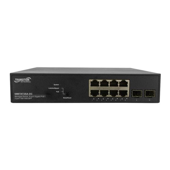
Page 13: Front And Back Panels
Front and Back Panels The SM8TAT2SA-DC front and back panels are shown and described below. Front Panel The SM8TAT2SA-DC front panel provides the switch LEDs, ports, and Mode/Reset pushbutton switch. Back Panel The SM8TAT2SA-DC back panel provides the 48-54VDC power input connection. -
Page 14: Led Descriptions
Transition Networks SM8TAT2SA-DC Install Guide LED Descriptions The LEDs on the front panel provide switch status checking and monitoring. The types of LEDs are as follows: System LED Indicates if the switch is powered up correctly, indicates if there is a system alarm triggered for troubleshooting. - Page 15 Transition Networks SM8TAT2SA-DC Install Guide By pressing the Mode/Reset button for less than 2 seconds to change LED modes (Link/Act/Speed Mode or PoE Mode) you can check the port status by reading the LED behaviors per the table below. Table 3: Port Status LEDs...
-
Page 16: Mode/Reset Button
Transition Networks SM8TAT2SA-DC Install Guide When PoE Mode LED Lit Color State Description Green The port is enabled and supplying power to connected device. An abnormal state, such as overload status, has been detected in the Amber switch. RJ45 Ports The port has no active network cable connected, or it is not connected a PoE PD device. -
Page 17: Installation
Transition Networks SM8TAT2SA-DC Install Guide Installation This section describes switch mounting, grounding, cable connection, configuration, and power connection. Caution: Before proceeding make sure you have read “Safety Warnings and Cautions” on page 2, and “Power Supply Warnings & Cautions !!“on page 23. -
Page 18: Rack Mount Dimensions
Transition Networks SM8TAT2SA-DC Install Guide Rack Mount Dimensions SM8TAT2SA-DC with Rack Mount Brackets Rack Mount Brackets 33814 Rev. A https://www.transition.com Page 18 of 43... -
Page 19: Rack Mounting
Transition Networks SM8TAT2SA-DC Install Guide Rack Mounting 1. Attach the mounting brackets to both sides of the chassis. Insert screws and tighten then with a screwdriver to secure the brackets. 2. Place the switch in the rack. Align the oval holes in the brackets with the mounting holes in the rack posts. -
Page 20: Mounting The Switch On Desk Or Shelf
Transition Networks SM8TAT2SA-DC Install Guide Mounting the Switch on Desk or Shelf Step 1: Verify that the workbench is sturdy and reliably grounded. Step 2: Attach the four adhesive rubber feet to the bottom of the switch. Attaching the Rubber Feet Grounding The back panel provides a ground screw. - Page 21 Neither DC input polarity may be earth grounded. If DC power distribution bus has one side tied to earth ground, then the use of an isolated DC-DC power Supply between the DC power distribution bus and SM8TAT2SA-DC is required to ensure that the PoE ports are isolated from earth ground as required by IEEE802.3af/at/bt specification.
-
Page 22: Safety: Equipment Using -48V Dc Power Supplies
Transition Networks SM8TAT2SA-DC Install Guide SAFETY: Equipment Using -48V DC Power Supplies Systems using -48V DC Power Supplies are intended for restricted access locations (dedicated equipment rooms, equipment closets, or similar) in accordance with Articles 110-5 (conductors), 110-6 (conductor sizes), 110-11... -
Page 23: Ethernet Interface Connecting (Rj45 Ethernet)
To connect to a PC, use a straight-through or a cross-over Ethernet cable. • To connect the SM8TAT2SA-DC to an Ethernet device, use UTP (Unshielded Twisted Pair) or STP (Shielded Twisted Pair) Ethernet cables. The RJ-45 connector pin assignments are shown below. -
Page 24: Poe Deployment Environments A And B
Environment B applications, i.e. building to building, copper to copper endpoint connections: 1) use an Ethernet network isolator module (PoE disabled), or 2) use mid-span injector(s) such as Transition Networks’ MIL-L100i or L1000i-at, between this switch’s PSE port and link partner PD port. -
Page 25: Ethernet Interface Connecting (Fiber, Sfp)
Transition Networks SM8TAT2SA-DC Install Guide Ethernet Interface Connecting (Fiber, SFP) For a 100 Mbps fiber port available, please prepare the LC connectors or SC connectors (with the use of an optional SC-to-LC adapter). For the available 1000 Mbps fiber ports, use mini-GBIC SFPs. These accept plug-in fiber transceivers that typically have an LC style connector. -
Page 26: Console Connection
Transition Networks SM8TAT2SA-DC Install Guide Console Connection A Console port is for local management by using a terminal emulator or a computer with terminal emulation software using these settings: • DB9 connector connect to computer COM port • Baud rate: 115200bps •... -
Page 27: Power Supply Warnings & Cautions
Optional Power Supplies The SM8TAT2SA-DC can be powered by either of two optional power supplies. Both the 25105 and 25104 power supplies are optional accessories that you must order separately. Power Connection Warning: Connect the power supply to the switch first while powered off, and then connect the power supply to power. -
Page 28: 25105 Industrial Din Rail Mounted Power Supply
Transition Networks SM8TAT2SA-DC Install Guide 25105 Industrial DIN Rail Mounted Power Supply For more information see the 25105 Product page. Features 91% High Efficiency 150% Peak Load Protected against Short Circuit, Overload, Over Voltage, and Overheating Convection air cooling DIN rail mountable... -
Page 29: 25104 Industrial Din Rail Mounted Power Supply
Transition Networks SM8TAT2SA-DC Install Guide 25104 Industrial DIN Rail Mounted Power Supply For more information see the 25104 Product page. Description: Industrial DIN Rail Mounted Power Supply; Input: 85-264 VAC, 124- 370 VDC; Output: 48~55 VDC, 5.0A, 240 Watts. Features... -
Page 30: Power Supply Mounting Instructions
Transition Networks SM8TAT2SA-DC Install Guide Power Supply Mounting Instructions Mount as shown in figure only, with input terminals down, or else sufficient cooling will not be possible. Admissible DIN Rail: TS35/7.5 or TS35/15. For DIN Rail fastening: 1. Tilt the unit slightly rearwards. -
Page 31: Power Supply Installation
Transition Networks SM8TAT2SA-DC Install Guide Power Supply Installation Each power supply is a DIN rail power supply with a 150% peak load capability (3 seconds) and high efficiency of up to 94%. They can be mounted on a TS35 Standard DIN rail. -
Page 32: Connecting Power
Or if the PD device is not isolated, then the chassis or earth voltage potential between the PD and SM8TAT2SA-DC must be maintained at the same voltage to eliminate the possibility of a voltage breakdown in the PD device or the SM8TAT2SA-DC. - Page 33 Transition Networks SM8TAT2SA-DC Install Guide port number will be fed PoE power. Priority is set in the Web UI at PoE Management > PoE Configuration. See the Web User Guide for details. IEEE Detection pulses are either 4-point or 2-point method. As with classification, a camera responding to either method might ignore one or the other.
-
Page 34: Initial Switch Configuration
Transition Networks SM8TAT2SA-DC Install Guide Initial Switch Configuration Initial Switch Configuration via Web Browser When you power up the switch the first time, a First Time Wizard is presented. On subsequent power ups, you can perform the initial switch configuration using a web browser. See the Quick Start Guide for First Time Wizard information. - Page 35 6. Enter the factory default username and password in login page. 7. Click “Login” to log into the switch. Note: The factory default Username and Password of the switch are both admin. See the SM8TAT2SA-DC Web User Guide for more information. 33814 Rev. A https://www.transition.com...
-
Page 36: Connect The Switch To Your Windows 10 Pc
13. Enter the default User name (admin) and Password (admin) all lower case. Initial Switch Configuration via CLI The CLI (Command Line Interface) can be accessed via telnet or SSH. See the SM8TAT2SA-DC CLI Reference for more information. 33814 Rev. A https://www.transition.com... -
Page 37: Troubleshooting
If the switch fails, isolate and correct the fault by determining the answers to the following questions and then taking the indicated action. First isolate the problem to the SM8TAT2SA-DC by troubleshooting other network gear (e.g., other switches, IP cameras, WAPs, midspan injectors, etc.) to isolate the problem to the SM8TAT2SA- 1. -
Page 38: Troubleshooting Poe Problems
WAPs. The actual power requirement can be advertised by the powered device, and the unused class power is returned to the switch power budget. Typical PD Power Requirements 1.8 Watts: Transition Networks’ M/GE-ISW-SFP-01-PD (Class 1 Powered Device (0.44 Watts - 3.84 □ Watts). -
Page 39: Box Label And Device Label
Describe any action(s) already taken to resolve the problem (e.g., changing mode, resetting, etc.): ___________________________________________________________________________________________ ___________________________________________________________________________________________ The model # and serial # of all other Transition Networks products in the network: ________________________ ___________________________________________________________________________________________ Describe your network environment (layout, cable type, cable distance, etc.): ____________________________ ___________________________________________________________________________________________ 33814 Rev. -
Page 40: Contact Us
Transition Networks SM8TAT2SA-DC Install Guide Any previous Return Material Authorization (RMA) numbers: __________________________________________ ___________________________________________________________________________________________ List third party equipment in the network (e.g., PCs, servers, switches, routers, IP cameras, WAPs, SFPs, etc.): ___________________________________________________________________________________________ __________________________________________________________________________________________ __________________________________________________________________________________________ Contact Us Technical Support: Technical support is available 24-hours a day... -
Page 41: Declaration Of Conformity
Declaration of Conformity Warranty To return a defective product for warranty coverage, contact Transition Networks’ technical support department for a return authorization number. Transition Network's technical support department can be reached 24‐hours a day by any of the following means: US and Canada: 1‐800‐260‐1312... -
Page 42: Limited Lifetime Warranty
The customer must pay for the non‐compliant product(s) return transportation costs to Transition Networks for evaluation of said product(s) for repair or replacement. Transition Networks will pay for the shipping of the repaired or replaced in‐warranty product(s) back to the customer (any and all customs charges, tariffs, or/and taxes are the customer’s responsibility). - Page 43 Minnetonka, MN 55343, U.S.A. tel: +1.952.941.7600 | toll free: 1.800.526.9267 | fax: 952.941.2322 sales@transition.com techsupport@transition.com customerservice@transition.com Copyright© 2020 Transition Networks. All rights reserved. Printed in the U.S.A. SM8TAT2SA-DC Install Guide, 33814 Rev. A 33814 Rev. A https://www.transition.com Page 43 of 43...
Need help?
Do you have a question about the SM8TAT2SA-DC and is the answer not in the manual?
Questions and answers