Advertisement
Transition Networks
SMxxTAT2SA Quick Start Guide
SMxxTAT2SA Quick Start Guide
The SMxxTAT2SA Smart Managed GbE PoE+ switch is the next‐generation Ethernet switch offering powerful L2
See the SMxxTAT2SA Install Guide for important Cautions
features with better functionality and usability.
and Warnings, as well as Features, Specifications, Front & Back Panel, LEDs, Mode/Reset button,
Installation, Package Contents, and Troubleshooting, Warranty, Support & Compliance information.
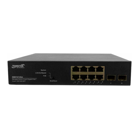
Front and Back Panels
The SM8TAT2SA front and back panels are shown below.
Mode/Reset Button
By pressing the Mode/Reset button for certain period of time, you can:
Change Port Status LED Mode: to read port status correctly in two modes (Link/Act/Speed mode or PoE mode).
Reset the Switch to reboot and get the switch back to the previously saved configuration settings.
Restore the Switch to Factory Defaults: press and hold the Reset button until all port LEDs light. This sets the
unit back to its factory default IP address; log back in to display the First Time Wizard.
LED Descriptions
The LEDs on the front panel provide switch status checking and monitoring. The three types of LEDs are:
System LED: Indicates if the switch is powered up correctly, indicates if there is a system alarm triggered for
troubleshooting.
Mode LEDs: Indicates the mode of all ports on the switch. You can press the
Mode/Reset button sequentially to switch among the two different modes
(Link/Activity/Speed mode and PoE mode).
Port Status LEDs: Indicates the current status of each port. Users can check these
LEDs to understand the port status in different modes, after changing the mode
by pressing Mode/Reset button.
Switch Installation
Desk, Shelf, or Rack Mount: See the Install Guide. Caution: The switch is an indoor device. If used with outdoor
devices, using a surge protector / suppressor is recommended. 802.3at compliant in Environment A when using
an isolated power supply. For 802.3at Environment B applications, see the Install Guide.
Install SFP Modules: You can install or remove SFP modules without having to power off the switch. 1. Insert the
module into the SFP port. 2. Press firmly so the SFP module seats into the connector. See the Install Guide.
Connect the AC Power Cord: 1. Connect the AC power cord to the switch AC power receptacle. 2. Connect the
other end of the AC power cord to an AC power outlet. 3. If the SYS LED is ON, power connection is correct.
33715 Rev. D
https://www.transition.com
Page 1 of 2
Advertisement
Table of Contents

Related Manuals for Transition Networks SM TAT2SA Series


Summary of Contents for Transition Networks SM TAT2SA Series
- Page 1 Transition Networks SMxxTAT2SA Quick Start Guide SMxxTAT2SA Quick Start Guide The SMxxTAT2SA Smart Managed GbE PoE+ switch is the next‐generation Ethernet switch offering powerful L2 See the SMxxTAT2SA Install Guide for important Cautions features with better functionality and usability. and Warnings, as well as Features, Specifications, Front & Back Panel, LEDs, Mode/Reset button, Installation, Package Contents, and Troubleshooting, Warranty, Support & Compliance information. Front and Back Panels The SM8TAT2SA front and back panels are shown below. Mode/Reset Button By pressing the Mode/Reset button for certain period of time, you can: Change Port Status LED Mode: to read port status correctly in two modes (Link/Act/Speed mode or PoE mode). Reset the Switch to reboot and get the switch back to the previously saved configuration settings. Restore the Switch to Factory Defaults: press and hold the Reset button until all port LEDs light. This sets the unit back to its factory default IP address; log back in to display the First Time Wizard. LED Descriptions The LEDs on the front panel provide switch status checking and monitoring. The three types of LEDs are: System LED: Indicates if the switch is powered up correctly, indicates if there is a system alarm triggered for troubleshooting. Mode LEDs: Indicates the mode of all ports on the switch. You can press the Mode/Reset button sequentially to switch among the two different modes (Link/Activity/Speed mode and PoE mode). Port Status LEDs: Indicates the current status of each port. Users can check these LEDs to understand the port status in different modes, after changing the mode by pressing Mode/Reset button. ...
- Page 2 Transition Networks SMxxTAT2SA Quick Start Guide First Time Wizard Configuration The first time you use the switch you can configure some basic settings, such as password, IP address, date and time, and system information. To use the First Time Wizard procedure: Step 1: Change default password; enter a new password and then enter it again, and click the Next button. Step 2: Set IP address; select “Obtain IP address via DHCP” or “Set IP address manually” to set the IP address, and click the Next button. Step 3: Set date and time; enable “Automatic data and time” or select manually to set date and time, and click the Next button. Step 4: Set system information; here you can set some system information to this device, such as “System contact”, “System name”, etc. When done click Next. Note: The First Time Wizard is used the first time you use the switch and after pressing the Reset button. Note: The factory default IP address = 192.168.1.77, the default Subnet Mask = 255.255.255.0, Default Gateway = 192.168.1.254, default Username = admin, and default Password = admin. Web UI Configuration The left‐hand menu contains two main tabs (Switch and DMS) each with several sub‐tabs for configuring and monitoring the switch’s major functions. The major Switch tab functions include Port, PoE, and VLAN Management, QoS, Spanning Tree, Diagnostics, and Maintenance. The DMS (Device Management System) tab functions are DMS Mode, Graphical Monitoring, Management, and Maintenance. CLI Configuration The command‐line interface (CLI) is a text‐based interface that you can access with either a direct serial connection to the device or a Telnet session. An RJ‐45 cable is used for connecting a terminal or terminal emulator to the SMxxTAT2SA RJ‐45 port to access the command‐line interface. Attach the RJ‐45 serial port on the switch front panel to the cable for Telnet/CLI configuration. Attach the other end of the DB‐9 cable to a PC running Telnet. Note that the CLI can only be accessed through telnet or SSH. Related Information: For Drivers, Firmware, Manuals, etc. go to the Product Support webpage (logon required). For Brochures, Data Sheets, etc. go to the Support Library (no logon required). Related manuals include SMxxTAT2SA Install Guide 33716, Web User Guide 33717, and CLI Reference 33718. ...
Need help?
Do you have a question about the SM TAT2SA Series and is the answer not in the manual?
Questions and answers