
Subscribe to Our Youtube Channel
Related Manuals for Transition Networks SM24DP4XA


Summary of Contents for Transition Networks SM24DP4XA
- Page 1 Transition Networks SM24DP4XA Install Guide SM24DP4XA Managed Fiber Switch 24-port 100/1000Base-X SFP + (4) 1G/10G SFP+ Install Guide 33769 Rev. A 33769 Rev. A https://www.transition.com Page 1 of 42...
-
Page 2: Safety Warnings And Cautions
Anyone using this product in such an application without express written consent of an officer of Transition Networks does so at their own risk and agrees to fully indemnify Transition Networks for any damages that may result from such use or sale. -
Page 3: Table Of Contents
Transition Networks SM24DP4XA Install Guide Contents Safety Warnings and Cautions ......................... 2 Chapter 1 - Overview ............................5 Key Features ................................5 Benefits ..................................5 Ordering Information ............................... 6 Specifications ................................6 Software Features ..............................7 Front Panel ................................16 LEDs ..................................17 RST (Reset) button ..............................19... - Page 4 SM24DP4XA Install Guide Chapter 5 - Regulatory and Safety Information ....................35 Certifications ................................35 Compliance and Safety Statements ........................35 SM24DP4XA EMC and EMI Report .........................36 CE EMC Test ................................36 FCC EMI Test ................................36 Declaration of Conformity .............................37 Class I, Division 2 / classe I, division 2 ........................37 High Risk Activities Disclaimer ..........................38...
-
Page 5: Chapter 1 - Overview
Chapter 1 - Overview The SM24DP4XA is a next generation Layer 2 managed switch with 128Gbps switching capacity. It provides up to (24) dual speed fiber slots and (4) 10Gig aggregation ports, it’s an ideal switch for fiber aggregation applications. -
Page 6: Ordering Information
Transition Networks SM24DP4XA Install Guide Ordering Information Description Managed fiber switch, (20) 100/1000BASE-X + (4) 100/1000 SFP/RJ-45 Combo + (4) SM24DP4XA 1G/10G SFP+ with 19” Rack Mount ears included 25131 Industrial DIN rail mounted power supply, 48VDC, 76.8Watts (option; order separately) 25079 Industrial DIN Rail Mounted Power Supply (option;... -
Page 7: Software Features
Transition Networks SM24DP4XA Install Guide Voltage and Frequency Input Voltage and Frequency AC Voltage 100-240 VAC AC Frequency 50-60 Hz DC Voltage Dual +24/+48 VDC or -24V/-48V VDC Industry Standards IEEE 802.3™, IEEE 802.3u, IEEE 802.3z, IEEE802.3ae, IEEE 802.3x, IEEE 802.3ad, IEEE 802.1D, Standard IEEE 802.1w, IEEE802.1s IEEE 802.1Q, IEEE 802.1p, IEEE 802.1ad,IEEE 1588v2, IEEE802.3ah,... - Page 8 Transition Networks SM24DP4XA Install Guide Used to support a Layer 2 multicast domain of snooping switches in the absence of a IGMP Querier multicast router IGMP snooping with proxy reporting or report suppression actively filters IGMP IGMP Proxy packets in order to reduce load on the multicast router...
- Page 9 Transition Networks SM24DP4XA Install Guide Quality of Service (QoS) Supports 8 hardware queues Hardware Queue • Strict priority and weighted round-robin (WRR) Scheduling • Queue assignment based on DSCP and class of service • Port based • 802.1p VLAN priority based Classification •...
- Page 10 Transition Networks SM24DP4XA Install Guide Ethernet OAM IEEE 802.3ah Link Supports IEEE 802.3ah Ethernet OAM (Operations, Administration & Management) IEEE 802.1ag & ITU-T Supports IEEE 802.1ag Ethernet CFM (Connectivity Fault Management) Y.1731 Flow OAM Supports ITU-T Y.1731 Performance Monitoring Loop Protection ITU-T G.8031...
- Page 11 Transition Networks SM24DP4XA Install Guide DC Input: 48V DC Current DC Power Status Operation Interface DC Voltage (V) Consumption (A) Consumption (W) Non-loading None 0.37 17.76 20-Port 1G SFP Full-load 4-Port 1G RJ45 0.82 39.36 5 minutes 4-Port 10G SFP...
- Page 12 Transition Networks SM24DP4XA Install Guide AC Power Consumption * Measure the AC power consumption after 30 minutes under full loading with wire speed forwarding. 1. AC 100V Input AC Current AC Voltage Power Apparent Real Power Status Test Status Consumption...
- Page 13 Transition Networks SM24DP4XA Install Guide 2. AC 110V Input AC Current AC Voltage Power Apparent Real Power Status Test Status Consumption Factor Power (VA) No Loading None 0.34 0.53 37.40 19.82 20-Port 1G SFP Full-load 5 minutes 4-Port 1G RJ45 0.63...
- Page 14 Transition Networks SM24DP4XA Install Guide 3. AC 220V Input AC Current AC Voltage Power Apparent Real Power Status Test Status Consumption Factor Power (VA) No Loading None 0.20 0.45 44.00 19.80 20-Port 1G SFP Full-load 5 minutes 4-Port 1G RJ45 0.37...
- Page 15 Transition Networks SM24DP4XA Install Guide 4. AC 240V Input AC Current AC Voltage Power Apparent Real Power Status Test Status Consumption Factor Power (VA) No Loading None 0.19 0.44 45.60 20.06 20-Port 1G SFP Full-load 5 minutes 4-Port 1G RJ45 0.36...
-
Page 16: Front Panel
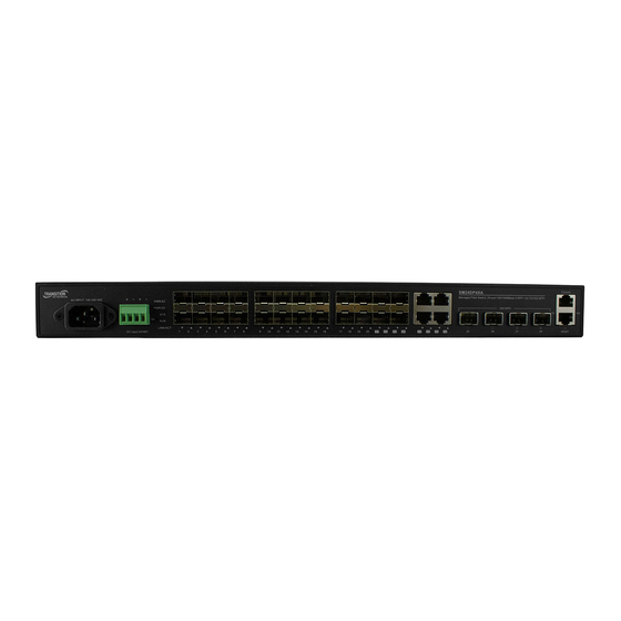
SM24DP4XA Install Guide Front Panel The SM24DP4XA front panel provides the ports, LEDs, buttons, and power inputs as shown and described below. Connectors: Provides 1 Console Port, 1 Management port, 20 100/1000 SFP slots, 4 100/1000 SFP/RJ-45 Combo, and 4 1G/10G SFP+ slots. -
Page 17: Leds
Transition Networks SM24DP4XA Install Guide LEDs The front panel LEDs provide with switch status checking and monitoring as shown and described below. AC/DC Power LED: Indicates if the switch is powered up correctly. SYS (System) Status LED : Indicates if the system is ready. - Page 18 Transition Networks SM24DP4XA Install Guide Table 4: Port Status LEDs Color State Description The port is enabled and established a link to connected device, and the Green connection speed is 1000Mbps. The port is transmitting/receiving packets, and connection speed is...
-
Page 19: Rst (Reset) Button
Back Panel The SM24DP4XA back panel provides the Ground Screw as shown below. Side Panel The SM24DP4XA left side panel has two fans. Make sure that the left side panel fan vents are not blocked after installation. 33769 Rev. A https://www.transition.com... -
Page 20: Manual Overview
Use a Web browser or the Command Line to initially configure the switch, and • Troubleshoot the switch. Note that this manual provides links to third party web sites for which Transition Networks is not responsible. For More Information A printed Quick Start Guide is shipped with each device. -
Page 21: Chapter 2 - Installing The Switch
5. Reliable Earthing: maintain reliable earthing of rack-mounted equipment; pay particular attention to supply connections other than direct connections to the branch circuit (e.g., use of power strips). Note: The SM24DP4XA left side panel has two fans. Do not block the left side panel fan vents during installation. 33769 Rev. A https://www.transition.com... -
Page 22: Mounting The Switch In A 19-Inch Rack
Transition Networks SM24DP4XA Install Guide Mounting the Switch in a 19-inch Rack 1. Attach the mounting brackets to both sides of the chassis. Insert screws and tighten with a screwdriver to secure the brackets. 2. Place the switch on a rack shelf in the rack. Push it in until the oval holes in the brackets align with the mounting holes in the rack posts. -
Page 23: Grounding The Switch
Transition Networks SM24DP4XA Install Guide Grounding the Switch The SM24DP4XA back panel provides the Ground Screw as shown below. ATTENTION: This case must be earth grounded. No DC input may be earth grounded. Use Isolated Power Supply. Installing SFP Modules You can install or remove a mini-GBIC SFP/SFP+ module from an SFP/SFP+ port without having to power off the switch. -
Page 24: Ac/Dc/Dc Redundant Power
Transition Networks SM24DP4XA Install Guide AC/DC/DC Redundant Power The three power inputs (AC/DC/DC) are redundant but in active/standby mode. There is failover between the three inputs but selecting primary and secondary is not supported. To select the primary and secondary inputs: 1. -
Page 25: Connecting To Dc Power
SM24DP4XA Install Guide Connecting to DC Power The SM24DP4XA supports dual 24/48 VDC or -24/-48 VDC inputs. The power source must be powered off when connecting and disconnecting this product. 1. Insert the negative or positive voltage DC power source wires into the DC INPUT terminals, respectively as shown below: 2. -
Page 26: Connecting Network Devices
Transition Networks SM24DP4XA Install Guide 3. Insert the terminal block connector prongs into the terminal block receptor. 4. Check the SYS LED. If it is ON, the power connection is correct. Connecting DC Power Input Connecting Network Devices The switch is designed to be connected to 10, 100 or 1000Mbps network cards in PCs and servers, as well as to other switches and hubs. -
Page 27: Connecting To Pcs, Servers, Hubs, And Switches
Transition Networks SM24DP4XA Install Guide Connecting to PCs, Servers, Hubs, and Switches 1. Attach one end of a twisted‐pair cable segment to the device’s RJ‐45 connector. 2. If the device is a network card and the switch is in the wiring closet, attach the other end of the cable segment to a modular wall outlet that is connected to the wiring closet. -
Page 28: Network Wiring Connections
Transition Networks SM24DP4XA Install Guide Network Wiring Connections The punch-down block is an integral part of many of the newer equipment racks. It is a part of the patch panel. Instructions for making connections in the wiring closet with this type of equipment follows. -
Page 29: Power Supply Specifications
Transition Networks SM24DP4XA Install Guide Power Supply Specifications Two DC Power Supply options are available which must be ordered separately. 25131 for 48VDC 25131 Industrial DIN rail mounted power supply, 48VDC, 76.8 Watts https://www.transition.com/products/accessory/25131a/ Features • Auto-Negotiation • Variable AC input range •... -
Page 30: Chapter 3 - Initial Switch Configuration
Transition Networks SM24DP4XA Install Guide Chapter 3 - Initial Switch Configuration Initial Switch Configuration via Web Browser After powering up the switch for the first time, you can perform the initial switch configuration using a web Web User Guide browser. For managing other switch features, see the for details. -
Page 31: Initial Switch Configuration Via Cli
Transition Networks SM24DP4XA Install Guide If your PC is configured correctly, the Login page displays as shown below. If you do not see the above login page, try these steps: Refresh the web page. Check to see if there is an IP address conflict issue. -
Page 32: Chapter 4 - Troubleshooting
Transition Networks SM24DP4XA Install Guide Chapter 4 - Troubleshooting Basic Troubleshooting 1. Make sure your switch model supports the feature or function attempted; see Key Features on page check the Release Notes for your particular firmware version. 2. Verify the install process; see Chapter 2 –... -
Page 33: Led Troubleshooting
Transition Networks SM24DP4XA Install Guide LED Troubleshooting Type Color Function Global PWR AC Green Lights when AC power is on. Global PWR DC Green Lights when DC power is on. Blinking when system is booting; Global Green Lit when system is coming up. -
Page 34: Record Device And System Information
After performing the troubleshooting steps, and before calling or emailing Technical Support, please record as much information as possible in order to help the Transition Networks Tech Support Specialist. 1. From the Web UI, select the Monitor > System > Information menu path. From the CLI, use the show commands needed to gather the information below or as requested by the TN Support Specialist. -
Page 35: Chapter 5 - Regulatory And Safety Information
Transition Networks SM24DP4XA Install Guide Chapter 5 - Regulatory and Safety Information Certifications Electromagnetic Emissions (EMC) CE, FCC Part 15 Class A Safety: UL 62368 Compliance and Safety Statements FCC, Class A: This product has been tested and found to comply with the limits for a Class A digital device pursuant to Part 15 of the FCC Rules. -
Page 36: Sm24Dp4Xa Emc And Emi Report
Transition Networks SM24DP4XA Install Guide SM24DP4XA EMC and EMI Report CE EMC Test Standard: EN 55032:2012/AC:2013 Class A EN61000‐3‐2:2014 EN61000‐3‐3:2013 AS/NZS CISPR 32:2013 Class A EN 55024:2010/A1:2015 Test Standards Test Item Test Standard and Procedure Radiated and Conducted European Standard EN 55032 Class A. Australian Standard AS/NZS CISPR 32 Class... -
Page 37: Declaration Of Conformity
Transition Networks SM24DP4XA Install Guide Declaration of Conformity Class I, Division 2 / classe I, division 2 Warning and Caution - Proper Installation and Operation (English) These devices are open-type devices that are to be installed in an enclosure only accessible with the use of a tool, suitable for the environment. -
Page 38: High Risk Activities Disclaimer
Nuclear Facilities, Aircraft Navigation or Aircraft Communication Systems, Air Traffic Control, Life Support, or Weapons Systems ("High Risk Activities"). Transition Networks and its supplier(s) specifically disclaim any expressed or implied warranty of fitness for such High Risk Activities. -
Page 39: Electrical Safety Warnings
Transition Networks SM24DP4XA Install Guide General Laser Safety Guidelines: When working around ports that support optical transceivers, observe the following safety guidelines to prevent eye injury: • Do not look into unterminated ports or at fibers that connect to unknown sources. -
Page 40: Chapter 6 - Service, Warranty & Tech Support
In no event shall Transition Networks be liable for incidental or consequential damages, costs, or expenses arising out of or in connection with the performance of the product delivered hereunder. Transition Networks will in no case cover damages arising out of the product being used in a negligent fashion or manner. -
Page 41: Contact Us
Transition Networks reserves the right to charge a $50 fee for all testing and shipping incurred, if after testing, a return is classified as “No Problem Found.”... - Page 42 Transition Networks 10900 Red Circle Drive Minnetonka, MN 55343 USA tel: +1.952.941.7600 | toll free: 1.800.526.9267 | fax: 952.941.2322 Copyright© 2020 Transition Networks. All rights reserved. Printed in the U.S.A. SM24DP4XA Install Guide, 33769 Rev. A 33769 Rev. A https://www.transition.com...
Need help?
Do you have a question about the SM24DP4XA and is the answer not in the manual?
Questions and answers