Kessel Staufix Instructions For Installation, Operation And Maintenance
Backwater valve
Hide thumbs
Also See for Staufix:
Table of Contents
Advertisement
Available languages
Available languages
Quick Links
ANLEITUNG FÜR EINBAU, BETRIEB UND WARTUNG
Rückstauverschluss Staufix / Staufix Control*
* mit Control Einheit zur Warnung und Statusmeldung per Funksignal
Installation
der Anlage wurde durchgeführt von Ihrem Fachbetrieb:
Name/Unterschrift
Stand 2019/11
Inbetriebnahme
Einweisung
Datum
Für fäkalienfreies
Abwasser
Zum Einbau in durch-
gehende Rohrleitungen
Freier Rohrquerschnitt
Stufenlose Anpassung
durch höhenverstell- und
neigbares Aufsatzstück
* Optische und akustische
Warnung bei Störungen.
Anbindung an enocean
Systeme
Ort
Stempel Fachbetrieb
D
GB
Page 31
F
Page 61
I
Pagina 91
NL Pagina 121
PL Strona 151
Produktvorteile
Sach-Nr. 016-023
Seite 1
®
Advertisement
Chapters
Table of Contents

Related Manuals for Kessel Staufix


Summary of Contents for Kessel Staufix
- Page 1 ANLEITUNG FÜR EINBAU, BETRIEB UND WARTUNG Seite 1 Rückstauverschluss Staufix / Staufix Control* Page 31 * mit Control Einheit zur Warnung und Statusmeldung per Funksignal Page 61 Pagina 91 NL Pagina 121 PL Strona 151 Produktvorteile Für fäkalienfreies Abwasser Zum Einbau in durch-...
-
Page 2: Table Of Contents
Inhaltsverzeichnis Allgemeine Hinweise zu dieser Anleitung Produktbeschreibung Sicherheit Montage Erstinbetriebnahme / Konfiguration Betrieb Wartung Fehlersuche Technische Daten 2 / 180 016-023... -
Page 3: Allgemeine Hinweise Zu Dieser Anleitung
Allgemeine Hinweise zu dieser Anleitung Liebe Kundin, lieber Kunde, als Premiumhersteller von innovativen Produkten für die Entwässerungstechnik bietet KESSEL ganzheitliche Systemlösungen und kundenorientierten Service. Dabei stellen wir höchste Qualitätsstandards und setzen konsequent auf Nachhaltigkeit. Nicht nur bei der Herstellung unserer Produkte, sondern auch im Hinblick auf den langfristigen Betrieb setzen wir uns dafür ein, dass Sie... - Page 4 Allgemeine Hinweise zu dieser Anleitung Produktbeschreibung, allgemein Abb. [1] Die Produkte Rückstauverschlüsse Staufix (im folgenden Rückstauverschluss benannt) sind für verschiedene Anwendungen vorgesehen: Anwendung / Funktion ↓ Variante Typ nach EN 13564.. Notverschluss Control Einheit Rückstauverschluss Staufix Control ..Typ2* Rückstauverschluss Staufix ..Typ2*...
- Page 5 Allgemeine Hinweise zu dieser Anleitung Funktionsprinzip Einbau in die Bodenplatte Abb. [2] Freiliegend, in der Abwasserleitung Abb. [3] 016-023 5 / 180...
-
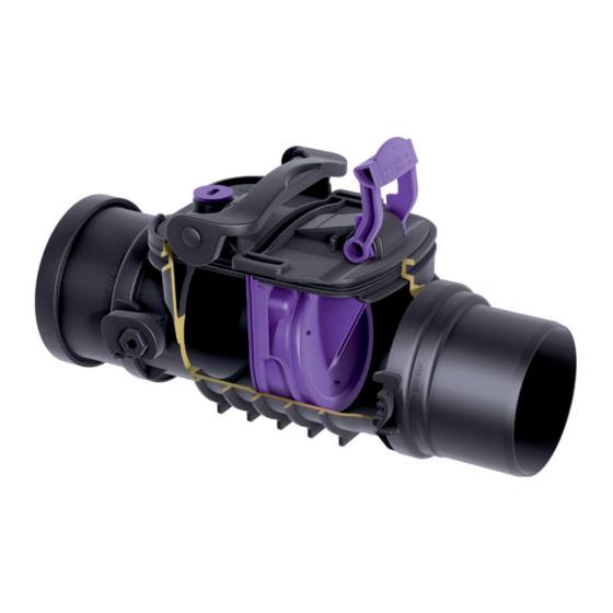
Page 6: Produktbeschreibung
Produktbeschreibung Produktbeschreibung Baugruppen und Funktionsmerkmale, Lieferumfang Montage in einer freiligenden Abwasserleitung Abb. [4] Grundkörper, mit (optional*): Rückstauklappe mit Notverschluss** Rückstauklappe* Notverschlusshebel Control Einheit Dokumente (EBA, Konformitätserklärung, Betriebsanleitungen der Zubehörteile) Verschlussschraube (Funktionskontrolle Notverschluss) Spitzende* Muffe* * vormontiert ** verschiedene Ausführungen 6 / 180 016-023... - Page 7 Produktbeschreibung Einbau in die Bodenplatte Hinweis: Bei Produktvariante Staufix Control wird ein Fernsignalempfänger empfohlen, da durch die Abdeckung des Aufsatzstückes<9> das optische und akustische Alarmsignal beeinträchtigt werden kann. Abb. [5] Grundkörper, mit (optional*, siehe Abb. [4]): Rückstauklappe ** 2. Rückstauklappe Notverschlusshebel Control Einheit Aufnahme für Aufsatzstück bzw.
-
Page 8: Sicherheit
Sicherheit Sicherheit Bestimmungsgemäße Verwendung Der Rückstauverschluss ist ausschließlich für die Montage in Rohrleitungen für fäkalienfreies Abwasser vorgesehen. Ein Einsatz der Control Einheit in explosionsgefährdeter Umgebung ist nicht zulässig. Alle nicht durch eine ausdrückliche und schriftliche Freigabe des Herstellers erfolgten • Um- oder Anbauten •... - Page 9 Sicherheit Allgemeine Sicherheitshinweise Gefahr durch besondere Örtlichkeit / Umgebungsbedingungen Gefahr durch giftige und gesundheitsgefährdende Dämpfe, Gase und Stoffe (z. B. Bakterien, Viren). Befindet sich der Rückstauverschluss in einem Schacht, sind darin notwendige Arbeiten ausschließlich durch Fachpersonal (siehe 3.2) durchzuführen. Gefahr für die Gesundheit Der Rückstauverschluss ist für fäkalienfreies Abwasser, welches gesundheitsgefährdende Stoffe enthalten kann, ausgelegt.
-
Page 10: Montage
Montage Montage Allgemeine Hinweise für die Montage – Die Beschreibung der einzelnen Montageschritte ist - sofern nicht anders beschrieben - an der Einbauvariante "Einbau in die Bodenplatte" ausgerichtet. Für die Montage in einer freiliegenden Leitung gelten dafür sinngemäß die gleichen Montageschritte. –... - Page 11 Bodenplatte 1 Verlängerungsstück für den vertieften Einbau mit Flansch, Art. 830070 2 Verlängerungsstück mit Flansch für den Einbau in WU-Beton, Art. 830075 3 Grundkörper bzw. Rückstauverschluss Staufix Typ 2 für Einbau in die Bodenplatte Abb. [7] 016-023 11 / 180...
- Page 12 Estrich c Dämmung d Betonplatte e Abdichtung f Schutzbeton 3 Verlängerungsstück für vertieften Einbau mit Flansch und Gegenflansch aus Edelstahl Art. 830073 4 Grundkörper bzw. Rückstauverschluss Staufix Typ 2 für Einbau in die Bodenplatte Abb. [8] 12 / 180 016-023...
- Page 13 Montage 4.3.1 Verlängerungsstück / Aufsatzstück montieren Nur so viele Verlängerungsstücke montieren, dass der Rückstauverschluss zu Wartungszwecken erreichbar ist. Maximale Einbautiefe 65 cm. Abb. [9] Abbildung zeigt Montage von Aufsatzstück mit Abdeckung <5> mit einem optionalen Verlängerungsstück <1>. Bei der Montage beachten: – Dichtungen <2> und <4> auf korrekten Sitz prüfen und Dichtlippen einfetten* –...
-
Page 14: Erstinbetriebnahme / Konfiguration
Erstinbetriebnahme / Konfiguration Erstinbetriebnahme / Konfiguration Im Betrieb muss der Notverschluss (1.3 Abb. 4) geöffnet (obere Position) sein. Control Einheit einschalten, Hinweis: Im Auslieferungszustand ist die Control Einheit deaktiviert. Ertönt beim Drücken der Taste Glocke ein Signalton und die grüne LED <1> blinkt einmal, ist die Control Einheit bereits eingeschaltet. - Page 15 Anwendungen, akzeptiert der gekoppelte Fernsignalgeber keine zusätzlichen Kopplungen mit einer neuen Control Einheit. Um bestehende Kopplungen am Fernsignalgeber aufzulösen, wenden Sie sich bitte an den KESSEL-Kundendienst. • Fernsignalgeber in die Steckdose einstecken, er ist 2 Minuten kopplungsbereit Abb. [12] • Taste Einlernen <2> der Control Einheit 5 Sekunden gedrückt halten.
- Page 16 Erstinbetriebnahme / Konfiguration Funkempfänger als Schaltsteckdose • Funkempfänger in die Steckdose einstecken • Kopplungstaste <1> 2 Sekunden gedrückt halten die LED <2> blinkt rot Abb. [13] • Taste Einlernen <2> der Control Einheit 5 Sekunden gedrückt halten. Die erfolgreiche Kopplung wird wie folgt quittiert: –...
- Page 17 Erstinbetriebnahme / Konfiguration Funktionskontrolle Sicherheitshinweise im Kapitel 3 beachten. 5.3.1 Dichtheitsprüfung nach EN 13564 Nur bei Rückstauverschluss Typ 2 (zwei Rückstauklappen). • Notverschluss <3> schließen (siehe 5.6) • Verschlussschraube <1> herausschrauben und Trichter <2> einschrauben • Wasser bis zur Prüfdruckhöhe von 10 cm in den Trichter (Zubehör: Art.
- Page 18 Erstinbetriebnahme / Konfiguration 5.3.2 Alarmfunktion überprüfen (Option, wenn Control Einheit <1> vorhanden) Akustischer Alarm und Alarm-LED • Verriegelungsdeckel <2> ausbauen, dazu Einhandverschluss <3>* öffnen und Verriegelungsdeckel <2> nach oben abheben * Grundkörper ab DN 150 haben zwei Einhandverschlüsse. Abb. [16] • Prüfschlauch <1>* wie abgebildet an der Unterseite des Verriegelungsdeckels <3>...
- Page 19 Erstinbetriebnahme / Konfiguration Verriegelungsdeckel <1> so auf einem mit Wasser gefüllten Gefäß <2> platzieren, dass der Prüfschlauch <3> mindestens 6 cm in das Wasser hineinragt Wird dadurch Rückstaualarm ausgelöst (siehe 6.2), ist die Funktion erfolgreich überprüft Sicherstellen, dass der Rückstaualarm durch Anheben des Verriegelungsdeckels (bis der Schlauch nicht mehr im Wasser ist) ausgeschaltet wird Abb.
- Page 20 Erstinbetriebnahme / Konfiguration Betriebsbereitschaft erklären Die Betriebsbereitschaft ist hergestellt, wenn: – alle unter 5.3 beschriebenen Punkte einwandfrei funktionieren. – Notverschluss geöffnet, siehe 5.6 – Einhandverschluss des Verriegelungsdeckel geschlossen, siehe Abb. [16] 20 / 180 016-023...
- Page 21 Erstinbetriebnahme / Konfiguration Abdeckung montieren Sicherstellen, dass Lock & Lift geöffnet ist. • Dichtung <4> auf Abdeckung <1> montieren. • Dichtung außen einfetten. • Abdeckung inkl. Dichtung schräg auf Aufsatzstück <2> einsetzen. • Schlüssel einführen und im Uhrzeigersinn bis zum Anschlag drehen. Schlüssel kann nun leicht entnommen werden.
- Page 22 Erstinbetriebnahme / Konfiguration Notverschluss Notverschluss öffnen • Notverschlusshebel <1> bis zum Anschlag in Pfeilrichtung <B> bewegen, der Notverschluss ist geöffnet (Betriebszustand). Notverschluss schließen • Notverschlusshebel <1> bis zum Anschlag in Pfeilrichtung <B> bewegen, der Notverschluss ist geschlossen. Es kann kein Wasser durch den Rückstauverschluss hindurchlaufen Abb.
-
Page 23: Betrieb
Betrieb Betrieb Bedienoptionen Selbstdiagnose, Vorgang Einschalten Ausschalten Koppeln Entkoppeln Alarm quittieren Handlung 5 Sec <2 Sec 2 Sec 10 Sec 10 Sec Blinkmuster: Signalton Signalton Reaktion der Rot (2x), 4x Signalton Blinkmuster: Blinkmuster: siehe 6.2 Control Einheit Rot + Grün Grün (3x) Grün (5x) Kapitel... - Page 24 Betrieb Rückmeldungen nach Tastendruck Signalton Bedeutung Grün, 1x blinken Nach Betätigen Taste Glocke = Betriebsbereit, nicht gekoppelt Grün, 2x blinken Nach Betätigen Taste Glocke = Betriebsbereit und gekoppelt ** alle 120 Sekunden Kann mit Taste Glocke ausgeschaltet werden alle 20 Sekunden Control Einheit einschalten Die Control Einheit ist dafür vorgesehen, dauerhaft eingeschaltet zu sein.
- Page 25 Betrieb Alarm quittieren Tritt ein Rückstauereignis auf, wird das an der Control Einheit angezeigt (siehe 6.2, C), ein Signalton ertönt. Signalton abschalten • Taste Glocke betätigen, der Signalton wir ausgeschaltet, die LEDs blinken weiterhin, bis der Rückstaualarm nicht mehr besteht Abb.
-
Page 26: Wartung
Wartung Wartung Sicherheitshinweise für die Wartung Gefahr durch giftige und gesundheitsgefährdende Dämpfe, Gase und Stoffe (z. B. Bakterien, Viren). Befindet sich der Rückstauverschluss in einem Schacht, sind darin notwendige Arbeiten ausschließlich durch Fachpersonal (siehe 3.2) durchzuführen. Gefahr des Ertrinkens im Anlagenschacht. Ein Anlagenschacht kann z.B. bei Überschwemmungen innerhalb kurzer Zeit voll Wasser laufen. - Page 27 Wartung Wartungstätigkeiten 7.4.1 Batterie der Control Einheit tauschen Hinweis: Die Daten für die gekoppelten Funkempfänger bleiben beim Batteriewechsel erhalten. • Sicherstellen, dass kein Rückstau anliegt • Ggf. Notverschlusshebel <4> in Position offen bringen • Einhandverschluss <3> in Position geöffnet (oben) bringen* • Control Einheit <1> ausbauen, dazu Schrauben<2> herausdrehen und die Control Einheit nach oben aus dem Verriegelungsdeckel <3>...
- Page 28 Wartung 7.4.2 Rückstauverschluss reinigen • Sicherstellen, dass kein Rückstau anliegt • Ggf. Notverschlusshebel in Position offen bringen • Verriegelungsdeckel <2> ausbauen, dazu • Einhandverschluss <6> auf Verschlussschraubenseite <1>* öffnen. Eine Betätigung von mehr als 90° hebt den Deckel zur leichteren Entnahme heraus. •...
-
Page 29: Fehlersuche
Rot blinken, 2x * Feuchtigkeit im Gehäuse der Control Einheit / Control Einheit ausbauen, ist der Fehler damit beseitigt, erneut einbauen und Funktionskontrolle (5.3) durchführen. Wenn Fehler weiterhin besteht: KESSEL Werkskundendienst informieren oder Verriegelungsdeckel mit Control Einheit erneuern * alle 20 Sekunden 016-023... -
Page 30: Technische Daten
Technische Daten Technische Daten Technische Daten Rückstauverschluss (inkl. Grundkörper) Parameter Wert Belastungsklasse (EN 124) A 15 (max. 1,5 t) bei Einbau in Bodenplatte Zulässige Abwassertemperatur 0-60 °C Technische Daten Control Einheit Parameter Wert Zulässige Umgebungstemperatur 0-40 °C Spannungsversorgung Lithium-Batterie CR 123 Spannung DC 3V Schutzklasse... - Page 31 INSTRUCTIONS FOR INSTALLATION, OPERATION AND MAINTENANCE Backwater valve Staufix / Staufix Control* * with control unit for warnings and status message by radio signal Product advantages For wastewater without sewage For installation in through pipes Fully open pipe passage Continuous adjustment...
- Page 32 Table of contents General information about these instructions Product description Safety Installation Initial operation / configuration Operation Maintenance Troubleshooting Technical data 32 / 180 016-023...
-
Page 33: General Information About These Instructions
General information about these instructions Dear customer, As a premium manufacturer of innovative products for draining technology, KESSEL offers integrated system solutions and customer-oriented service. We hereby aspire to the highest quality standards and focus firmly on sustainability - not just when it comes to manufacturing our products, but also with respect to their long-term operation, so that you and your property are protected long term. - Page 34 General information about these instructions Product description, general Ill. [1] The backwater valves Staufix (referred to as backwater valve below) have been designed for various applications: Application / function ↓ Variant Type in accordance Emergency closure Control unit with EN 13564 Backwater valve Staufix Control ..type 2*...
- Page 35 General information about these instructions How it works Installation in the concrete slab Ill. [2] Exposed, in the drainage pipe Ill. [3] 016-023 35 / 180...
-
Page 36: Product Description
Product description Product description Assemblies and functional characteristics, scope of delivery Installation in an exposed drainage pipe Ill. [4] Drain body, with (optional*): Backwater flap with emergency closure** Backwater flap* Emergency closure lever Control unit Documents (installation instructions, Declaration of Conformity, operating instructions for the accessory parts) Screwed sealing plug (functional check emergency closure) Spigot*... - Page 37 Product description Installation in the concrete slab Note: With the product variant Staufix Control a remote signal generator is recommended, since the optical and visual alarm signal can be impaired by the cover on the upper section <9>. Ill. [5] Drain body, with (optional*, see Ill. [4]): Backwater flap ** 2.
-
Page 38: Safety
Safety Safety Intended use The backwater valve is designed exclusively for installation in pipes for wastewater without sewage. The control unit must not be used in a potentially explosive environment. • modifications or attachments • use of non-genuine spare parts •... - Page 39 Safety General safety notes Hazard due by particular location / ambient conditions Hazard due to toxic and harmful fumes, gases and substances (e. g. bacteria, viruses). If the backwater valve is located in an inspection chamber, any necessary work must always be carried out by skilled personnel 3.2.2).
-
Page 40: Installation
Installation Installation General installation information – Unless specified otherwise, the individual installation steps described are for the installation type "Installation in a concrete slab". The same installation steps apply analogously for installation in an exposed pipe. – Make sure there is a sufficient gap to the wall or objects for maintenance work to be carried out. - Page 41 1 Extension section for deeper installation with flange, art. 830070 2 Extension section with flange for installation in waterproof concrete, art. 830075 3 Drain body or backwater valve Staufix type 2 for installation in a concrete slab Ill. [7] 016-023...
- Page 42 Protective concrete 3 Extension section for deeper installation with flange and counterflange made of stainless steel art. 830073 4 Drain body or backwater valve Staufix type 2 for installation in a concrete slab Ill. [8] 42 / 180 016-023...
- Page 43 Installation 4.3.1 Installation of the extension section / upper section Only install as many extension sections as are necessary for the backwater valve to be reached for maintenance purposes. Maximum installation depth 65 cm Ill. [9] Illustration shows the installation of the upper section with cover <5>...
-
Page 44: Initial Operation / Configuration
Initial operation / configuration Initial operation / configuration In operation, the emergency closure (1.3 Fig. 4) must be opened (upper position). Switch the control unit on Note: The control unit is disabled when the equipment is delivered. If an acoustic signal is sounded and the green LED <1>... - Page 45 To cancel existing couplings on the audible alarm unit, please contact KESSEL Customer Services. • Insert the audible alarm unit into the socket, it is ready for coupling for 2 minutes Ill.
- Page 46 Initial operation / configuration Radio receiver as switched socket • Insert the radio receiver in the socket • Press the coupling key <1> for 2 seconds , the LED <2> flashes red Ill. [13] • Press the teach key <2> on the control unit for 5 seconds. Successful coupling is acknowledged as follows: –...
- Page 47 Initial operation / configuration Functional check Follow the safety instructions 3 chapter 3. 5.3.1 Watertightness test in accordance with EN 13564 Only for backwater valve type 2 (two backwater flaps). • Close the emergency closure <3> (se5.6) • Screw the screwed sealing plug out <1> and the funnel <2>...
- Page 48 Initial operation / configuration 5.3.2 Checking the alarm function (Option, if control unit <1> is available) Acoustic alarm and alarm LED • Remove the lockable cover <2>, to do this, open the one-handed closure <3>* and lift the lockable cover <2> up and off * Drain bodies from DN 150 have two one-handed closures.
- Page 49 Initial operation / configuration Place the lockable cover <1> onto a vessel filled with water <2> in such a way that the test hose <3> projects at least 6 cm into the water If this triggers a backwater alarm (see 6.2) the function has been tested successfully Make sure that the backwater alarm is switched off by lifting the lockable cover (until the hose is no longer in the water)
- Page 50 Initial operation / configuration Declare ready for operation The system is ready for operation if: – all the points described under 5.3 work perfectly. – the emergency closure is opened 5.6 – the one-handed closure of the lockable cover is closed, see Ill. [16] 50 / 180 016-023...
- Page 51 Initial operation / configuration Install cover Make sure that "lock & lift" is opened. • Affix sealing gasket <4> to the cover <1>. • Lubricate seal on outer side. • Tilt cover with affixed sealing gasket and insert onto upper section <2>. •...
- Page 52 Initial operation / configuration Emergency closure Open the emergency closure • Move the emergency closure lever <1> as far as it will go in the direction of the arrow <B>, the emergency closure is opened (operating state). Close the emergency closure • Move the emergency closure lever <1> as far as it will go in the direction of the arrow <A>, the emergency closure is closed.
-
Page 53: Operation
Operation Operation Operating options Self-diagnostics, Procedure Switch on Switch off Couple Decouple acknowledge alarm Action 5 Sec 2 Sec 10 Sec 10 Sec <2 Sec Acoustic Flashing Acoustic signal signal Reaction by pattern: red 4x acoustic Flashing Flashing see 6.2 the control unit (2x), signal... - Page 54 Operation Feedback after pressing keys Acoustic Meaning signal Green, flashing When bell key has been pressed = ready for operation, not coupled Green, flashing When bell key has been pressed = ready for operation and coupled ** every 120 seconds can be switched off with the bell key every 20 seconds Switch the control unit on...
- Page 55 Operation Acknowledge the alarm If a backwater event occurs, this is indicated on the control unit (see 6.2, C), an acoustic signal is sounded. Switching the acoustic signal off • Press the bell key, the acoustic signal is switched off, the LEDs continue to flash until the backwater alarm is no longer pending Ill.
-
Page 56: Maintenance
Maintenance Maintenance Maintenance safety instructions Hazard due to toxic and harmful fumes, gases and substances (e. g. bacteria, viruses). If the backwater valve is located in an inspection chamber, any necessary work must always be carried out by skilled personnel 3.2.2). Drowning hazard in the system chamber. - Page 57 Maintenance Maintenance tasks 7.4.1 Replacing the control unit battery Note: The data for the coupled radio receivers is retained when the battery is replaced. • Make sure there is no backwater • If necessary, move the emergency closure lever <4> to the open position •...
- Page 58 Maintenance 7.4.2 Cleaning the backwater valve • Make sure there is no backwater • If necessary, move the emergency closure lever to the open position • Remove lockable cover* <2>, for this • Lift the one-hand lever <6> on screw-plug side <1>*.
-
Page 59: Troubleshooting
Humidity in the control unit housing / remove control unit, if this eliminates the fault, install again and carry out a functional check (5.3). If the fault persists: inform KESSEL Factory Customer Service or replace the lockable cover with control unit... -
Page 60: Technical Data
Technical data Technical data Technical data backwater valve (incl. drain body) Parameter Value Load class (EN 124) A 15 (max. 1.5 t) for installation in concrete slab Permissible wastewater temperature 0-60 °C Technical data control unit Parameter Value Permissible ambient temperature 0-40 °C Voltage supply Lithium battery CR 123... - Page 61 INSTRUCTIONS DE POSE, D‘UTILISATION ET DE MAINTENANCE Clapet anti-retour Staufix / Staufix Control* * avec unité de contrôle d’alarme et de message d’état par signal radio Avantages du produit Pour eaux usées sans matières fécales Pose dans des canalisa- tions sans joints Ouverture libre Adaptation à...
- Page 62 Sommaire Conseils d'ordre général concernant les présentes instructions Description du produit Sécurité Montage Première mise en service / configuration Fonctionnement Maintenance Aide au diagnostic Caractéristiques techniques 62 / 180 016-023...
-
Page 63: Conseils D'ordre Général Concernant Les Présentes Instructions
Chère cliente, cher client, En qualité de producteur de pointe de produits novateurs dans le domaine de la technique d’assainissement, KESSEL propose des réponses systématiques globales et un service orienté aux besoins de la clientèle. Nous misons simultanément sur les normes de qualité... - Page 64 Conseils d'ordre général concernant les présentes instructions Description générale du produit Fig. [1] Les clapets anti-retours de la gamme Staufix (ci-après nommés « clapet anti-retour ») sont prévus pour différentes applications : Application / fonction ↓ Variante Type suivant Verrouillage Unité de contrôle EN 13564..
- Page 65 Conseils d'ordre général concernant les présentes instructions Principe de fonctionnement Pose dans la dalle de fondation Fig. [2] Hors sol, dans la conduite d’eau usée Fig. [3] 016-023 65 / 180...
-
Page 66: Description Du Produit
Description du produit Description du produit Sous-groupes et éléments fonctionnels, détail de livraison Montage dans une conduite d'eau usée hors sol Fig. [4] Corps de base, avec (en option*) : Clapet anti-retour avec verrouillage d'urgence** Clapet anti-retour* Levier de verrouillage d'urgence Unité... - Page 67 Pose dans la dalle de fondation Nota Bene : nous recommandons l’emploi d’un récepteur de signaux à distance pour la variante Staufix Control, étant donné que le tampon de la rehausse <9> risque d’entraver le signal d'alarme optique et acoustique. Fig. [5] Corps de base, avec (en option*, voir Fig.
-
Page 68: Sécurité
Sécurité Sécurité Utilisation conforme à l'usage prévu Le clapet anti-retour est exclusivement prévu pour le montage dans des canalisations destinées aux eaux usées sans matières fécales. L'utilisation de l’unité de contrôle dans des zones à risque d'explosion est interdite. Il faut savoir, à défaut d'une autorisation expresse et écrite du fabricant, que toutes les •... - Page 69 Sécurité Consignes de sécurité générales Risque lié à des lieux particuliers / aux conditions ambiantes Risque lié aux vapeurs, gaz et substances toxiques ou nuisible à la santé (p. ex. les bactéries, virus). Les travaux à effectuer sur un clapet anti-retour logé dans un regard demeurent réservés au domaine de compétence exclusif de personnes (voir 3.2).
-
Page 70: Montage
Montage Montage Conseils de montage d'ordre général – Sauf description dérogatoire, les différentes étapes de montage sont décrites en prenant la variante d'installation d’une « pose dans la dalle de fondation » pour exemple. Les mêmes étapes de montage s’appliquent par analogie au montage dans une conduite hors sol. –... - Page 71 1 Pièce de rallonge pour installation à encastrer avec bordure, Réf. n° 830070 2 Pièce de prolongation avec bride pour la pose dans du béton étanche, Réf. n° 830075 3 Corps de base ou clapet anti-retour Staufix Type 2 pour la pose dans la dalle de fondation Fig. [7]...
- Page 72 3 Pièce de rallonge pour installation à encastrer avec bordure et contre-bride en acier inoxydable, Réf. n° 830073 4 Corps de base ou clapet anti-retour Staufix Type 2 pour la pose dans la dalle de fondation Fig. [8] 72 / 180...
- Page 73 Montage 4.3.1 Montage de la pièce de rallonge / de la rehausse Monter uniquement le nombre de pièces de rallonge nécessaire pour assurer l’accessibilité du clapet anti-retour à des fins de maintenance. Profondeur d'installation maximale de 65 cm Fig. [9] La figure montre le montage d’une rehausse avec tampon <5>...
-
Page 74: Première Mise En Service / Configuration
Le verrouillage d'urgence (voir 1.3 Fig. 4) doit demeurer ouvert en fonctionnement (position en haut). Activation de l’unité de contrôle (Staufix Control) Nota Bene : l’unité de contrôle est désactivée en l’état de livraison. Si lorsque vous appuyez sur le bouton cloche, un signal sonore retentit et la diode verte <1>... - Page 75 à distance commuté n'accepte aucune commutation supplémentaire à une autre unité de contrôle. Veuillez contacter le service après-vente KESSEL si vous devez supprimer des commutations existantes sur l’émetteur de signaux à distance. Fig. [12] •...
- Page 76 Première mise en service / configuration • Appuyer sur le bouton d’apprentissage <2> de l’unité de contrôle pendant 5 secondes. Un signal acoustique retentit et la diode <1> passe au clignotement vert, 3 fois, lors d’une commutation réussie Récepteur radio comme prise de commutation •...
- Page 77 Première mise en service / configuration Contrôle fonctionnel Observer les consignes de sécurité du chapitre 3. 5.3.1 Essai d'étanchéité suivant EN 13564 Uniquement en cas de clapet anti-retour de type 2 (deux clapets anti-retour). • Fermer le verrouillage d'urgence <3> (voir 5.6) •...
- Page 78 Première mise en service / configuration 5.3.2 Contrôle de la fonction d'alarme (Option, si l’unité de contrôle <1> est montée) Alarme acoustique et diode d'alarme • Dévisser le couvercle verrouillable <2> en ouvrant la fermeture rapide à une main <3>* et soulever le couvercle verrouillable <2>...
- Page 79 Première mise en service / configuration Placer le couvercle verrouillable <1> sur un récipient rempli d’eau <2> de sorte que le tuyau d’essai <3> soit immergé d’au moins 6 cm Le déclenchement d’une alarme de reflux (voir 6.2) est signe d’un contrôle réussi de la fonction d'alarme S'assurer de la désactivation de l’alarme de reflux en soulevant le couvercle verrouillable (jusqu’à...
- Page 80 Première mise en service / configuration Établissement de la disponibilité au fonctionnement La disponibilité au fonctionnement est établie si : – tous les points suivant 5.3 fonctionnent parfaitement. – le verrouillage d'urgence est ouvert, voir 5.6. – la fermeture rapide à une main du couvercle verrouillable est fermée, voir Fig. [16] 80 / 180 016-023...
- Page 81 Première mise en service / configuration Montage du tampon S'assurer que le Lock & Lift est ouvert • Joint <4> monté sur le couvercle <1>. • Joint d'étanchéité extérieur. • Couvercle incl. joint dans l'angle de section supérieure <2>. • insertion de la clé et la rotation dans le sens des aiguilles jusqu'à...
- Page 82 Première mise en service / configuration Verrouillage d'urgence Ouverture du verrouillage d'urgence • Déplacer le levier du verrouillage d'urgence <1> jusqu’à la butée dans le sens de la flèche <B> ; le verrouillage d'urgence est ouvert (état de fonctionnement). Fermeture du verrouillage d'urgence •...
-
Page 83: Fonctionnement
Fonctionnement Fonctionnement Options de commande Autodiagnostic, Opération Activation Désactivation Commuter Décommuter acquittement d’alarme Action <2 Sec 5 Sec 2 Sec 10 Sec 10 Sec Signal Signal Réaction de Clignotement : Signal acoustique acoustique l’unité de rouge (2 fois), acoustique voir 6.2 Clignotement : Clignotement : contrôle rouge + vert... - Page 84 Fonctionnement Rétrosignaux après l’actionnement du bouton Diode Signal Signification acoustique Clignotement vert Après l'actionnement du bouton avec la cloche = en 1 fois ordre de marche, non commuté Clignotement vert Après l'actionnement du bouton avec la cloche = en 2 fois ordre de marche et commuté ** toutes les 120 secondes Désactivation possible via le bouton avec la cloche toutes les 20 secondes...
- Page 85 Fonctionnement Acquittement d’une alarme Lorsqu’un événement de reflux est affiché sur l’unité de contrôle (voir 6.2, C), un signal acoustique retentit. Déconnexion du signal acoustique • Appuyer sur le bouton cloche, le signal sonore est désactivé, les diodes continuent de clignoter jusqu’à ce que l’alarme de reflux soit désactivée Fig.
-
Page 86: Maintenance
Maintenance Maintenance Consignes de sécurité spécifiques à la maintenance Risque lié aux vapeurs, gaz et substances toxiques ou nuisible à la santé (p. ex. les bactéries, virus). Les travaux à effectuer sur un clapet anti-retour logé dans un regard sont réservés aux personnes qualifiées (voir 3.2). - Page 87 Maintenance Interventions de maintenance 7.4.1 Remplacement de la batterie de l’unité de contrôle Nota Bene : le remplacement de la batterie n’a aucun effet sur les données des récepteurs radio commutés. • S'assurer qu’il n’y a pas de reflux dans le système •...
- Page 88 Maintenance 7.4.2 Nettoyage du clapet anti-retour • S'assurer qu’il n’y a pas de reflux dans le système • Au besoin, amener le levier du verrouillage d'urgence à la position ouverte • Démonter le couvercle de verrouillage* (2), puis • D’une main, ouvrir la fermeture (6) du côté du bouchon (1).
-
Page 89: Aide Au Diagnostic
(5.3) si cette mesure a permis de remédier à l’erreur. Si l’erreur persiste : informer le service après-vente KESSEL ou remplacer le couvercle verrouillable avec l’unité de contrôle * toutes les 20 secondes... -
Page 90: Caractéristiques Techniques
Caractéristiques techniques Caractéristiques techniques Caractéristiques techniques du clapet anti-retour (y compris le corps de base) Paramètre Valeur Classe de charge (EN 124) A 15 (maximum 1,5 t) si pose dans la dalle de fondation Température admissible des eaux 0 à 60 °C usées Caractéristiques techniques de l’unité de contrôle Paramètre Valeur Température ambiante admissible... - Page 91 ISTRUZIONI PER L‘INSTALLAZIONE, IL FUNZIONAMENTO E LA MANUTENZIONE Valvola antiriflusso Staufix / Staufix Control* * con unità di controllo per l‘avvertimento e la segnalazione di stato tramite segnale radio Vantaggi del prodotto Per le acque di scarico non contenenti sostanze fecali Per l’installazione nelle...
- Page 92 Indice Avvertenze generali in merito alle presenti istruzioni Descrizione del prodotto Sicurezza Montaggio Prima messa in funzione / Configurazione Funzionamento Manutenzione Ricerca di errori Dati tecnici 92 / 180 016-023...
- Page 93 Avvertenze generali in merito alle presenti istruzioni Cara cliente, caro cliente, in qualità di produttore premium di prodotti innovativi per la tecnica di drenaggio, KESSEL offre soluzioni di sistema integrate e un servizio orientato al cliente. Puntiamo sui massimi standard qualitativi e ci impegniamo coerentemente per la sostenibilità – non ci impegniamo solo nella produzione dei nostri prodotti, ma anche rispetto al funzionamento a lungo termine, in modo che la vostra proprietà...
- Page 94 Avvertenze generali in merito alle presenti istruzioni Descrizione del prodotto, in generale Ill. [1] I prodotti relativi ai valvole antiriflusso Staufix (indicati di seguito come valvola antiriflusso) sono pensati per diverse applicazioni: Applicazione / Funzione ↓ Variante Tipo a norma EN Chiusura di Unità...
- Page 95 Avvertenze generali in merito alle presenti istruzioni Principio di funzionamento Installazione nel pavimento Ill. [2] Non interrato, nel condotto delle acque di scarico Ill. [3] 016-023 95 / 180...
- Page 96 Descrizione del prodotto Descrizione del prodotto Gruppi costruttivi e caratteristiche funzionali, dotazione Montaggio in un condotto delle acque di scarico non interrato Ill. [4] Corpo base, con (opzionale*): Clapet antiriflusso con chiusura di emergenza** Clapet antiriflusso* Leva della chiusura di emergenza Unità...
- Page 97 Descrizione del prodotto Installazione nel pavimento Avvertenza: per la variante di prodotto Staufix Control si raccomanda un ricevitore di segnali a distanza, in quanto la copertura del rialzo <9> può ostacolare il segnale d'allarme ottico e acustico. Ill. [5] Corpo base, con (opzionale*, vedere Ill. [4]): Clapet antiriflusso** 2°...
- Page 98 Sicurezza Sicurezza Uso conforme alla destinazione Il valvola antiriflusso è pensato esclusivamente per il montaggio nelle tubazioni per le acque di scarico non contenenti sostanze fecali. Un impiego dell'unità di controllo negli ambienti a rischio di esplosione non è ammesso. In assenza di un’autorizzazione espressa e in forma scritta da parte del produttore, •...
- Page 99 Sicurezza Avvertenze di sicurezza generali Pericoli causati da particolari condizioni locali / ambientali Pericolo a causa di vapori, gas o sostanze velenose o nocive (ad esempio batteri o virus). Qualora la valvola antiriflusso si trovi in un pozzetto, i lavori necessari all’interno di quest’ultimo dovranno essere eseguiti esclusivamente da personale specializzato (vedere 3.2).
- Page 100 Montaggio Montaggio Avvertenze generali per il montaggio – La descrizione dei singoli passi di montaggio – ove non descritto diversamente – si riferisce alla variante della posa “Installazione nel pavimento”. Per il montaggio in un condotto non interrato valgono conformemente al senso gli stessi passi di montaggio. –...
- Page 101 1 Pezzo di prolunga per l’installazione più profonda con flangia, articolo 830070 2 Pezzo di prolunga con flangia per l'installazione nel calcestruzzo impermeabile, articolo 830075 3 Corpo base ovvero valvola di non ritorno Staufix tipo 2 per l’installazione nel pavimento Ill. [7] 016-023...
- Page 102 Calcestruzzo protettivo 3 Pezzo di prolunga per l’installazione più profonda con flangia e contro-flangia in acciaio inossidabile, articolo 830073 4 Corpo base ovvero valvola di non ritorno Staufix tipo 2 per l’installazione nel pavimento Ill. [8] 102 / 180...
- Page 103 Montaggio 4.3.1 Montaggio del pezzo di prolunga / rialzo Montare solo un numero di pezzi di prolunga che consenta di raggiungere la valvola antiriflusso a scopo di manutenzione. Profondità di posa massima di 65 cm Ill. [9] L'immagine mostra il montaggio del rialzo con la copertura <5>...
- Page 104 Prima messa in funzione / Configurazione Prima messa in funzione / Configurazione Durante il funzionamento, la chiusura di emergenza (1.3, figura 4) deve essere aperta (posizione superiore). Accensione dell’unità di controllo Indicazione: l’unità di controllo è disattivata al momento della consegna.
- Page 105 Per annullare gli accoppiamenti presenti sul segnalatore a distanza, rivolgersi al servizio clienti KESSEL. • Innestare il segnalatore a distanza nella presa; entro 2 minuti sarà pronto all’accoppiamento • Tenere premuto il tasto di accoppiamento <2>...
- Page 106 Prima messa in funzione / Configurazione Ricevitore radio quale presa di commutazione • Innestare il ricevitore radio nella presa • Tenere premuto il tasto di accoppiamento <1> per 2 secondi , il LED <2> lampeggia in rosso Ill. [13] • Tenere premuto il tasto di accoppiamento <2> dell’unità...
- Page 107 Prima messa in funzione / Configurazione Controllo di funzionamento Rispettare le avvertenze di sicurezza nel capitolo 3. 5.3.1 Prova di ermeticità a norma EN 13564 Solo con valvola antiriflusso di tipo 2 (due clapet antiriflusso). • Chiudere la chiusura di emergenza <3> (vedere 5.6) •...
- Page 108 Prima messa in funzione / Configurazione 5.3.2 Verificare la funzione di allarme (Opzionale, se è disponibile l’unità di controllo <1>) Allarme acustico e LED d’allarme • Smontare il coperchio di chiusura <2>; a tale fine, aprire la chiusura mono - manuale <3>* e togliere il coperchio di chiusura <2>...
- Page 109 Prima messa in funzione / Configurazione Collocare il coperchio di chiusura <1> su un recipiente pieno d'acqua <2> in modo tale che il tubo flessibile di prova <3> sia immerso per almeno 6 cm in acqua Se questo attiva l'allarme di ristagno (vedere 6.2), il funzionamento è...
- Page 110 Prima messa in funzione / Configurazione Dichiarazione della condizione di prontezza per il funzionamento La condizione di prontezza per il funzionamento è realizzata se: – Tutti i punti descritti al capitolo 5.3 funzionano senza problemi. – La chiusura di emergenza è aperta, vedere 5.6 –...
- Page 111 Prima messa in funzione / Configurazione Chiusura di emergenza Apertura della chiusura di emergenza • Spostare la leva della chiusura di emergenza <1> fino all'arresto in direzione della freccia <B>; la chiusura di emergenza è aperta (stato di funzionamento). Chiusura della chiusura di emergenza •...
- Page 112 Funzionamento Funzionamento Opzioni di comando Auto- Disaccop- diagnostica, Procedimento Accensione Spegnimento Accoppiamento piamento conferma dell’allarme Azione <2 Sec 5 Sec 2 Sec 10 Sec 10 Sec Schema di Segnale acustico Segnale acustico Reazione lampeggio: 4 segnali Schema di Schema di dell’unità...
- Page 113 Funzionamento Reazioni dopo la pressione dei tasti Segnale Significato acustico Verde, 1 sì Dopo l’azionamento del tasto con il simbolo della lampeggio campana = pronto al funzionamento, non accoppiato Verde, 2 Dopo l’azionamento del tasto con il simbolo della sì lampeggi campana = pronto al funzionamento e accoppiato** ogni 120 secondi...
- Page 114 Funzionamento Conferma dell’allarme La presenza di un evento di ristagno verrà segnalata dall’unità di controllo (vedere 6.2, C); verrà emesso un segnale acustico. Spegnimento del segnale acustico • Azionare il tasto con il simbolo della campana; il segnale acustico viene spento, i LED continuano a lampeggiare fino alla scomparsa dell’allarme di ristagno Ill.
- Page 115 Funzionamento Disaccoppiamento del ricevitore radio • Tenere premuti contemporaneamente per 5 secondi il tasto con il simbolo della campana e il tasto di accoppiamento; verrà emesso 1 segnale acustico e il LED <1> lampeggerà 5 volte in verde. Tutti gli accoppiamenti sono annullati. In presenza di un allarme di ristagno non verrà...
- Page 116 Manutenzione Manutenzione Avvertenze di sicurezza per la manutenzione Pericolo a causa di vapori, gas o sostanze velenose o nocive (ad esempio batteri o virus). Qualora la valvola antiriflusso si trovi in un pozzetto, i lavori necessari all’interno di quest’ultimo dovranno essere eseguiti esclusivamente da personale specializzato (vedere 3.2).
- Page 117 Manutenzione Mansioni di manutenzione 7.4.1 Sostituzione della batteria dell’unità di controllo Indicazione: i dati per i ricevitori radio accoppiati si conservano anche in caso di sostituzione della batteria. • Accertare che non sia presente nessun ristagno • Eventualmente portare la leva della chiusura di emergenza <4>...
- Page 118 Manutenzione 7.4.2 Pulizia della valvola antiriflusso • Accertare che non sia presente nessun ristagno • Eventualmente portare la leva della chiusura di emergenza in posizione aperta • Smontare il coperchio di chiusura*<2>; a tale fine, • aprire la chiusura mono - manuale <6> sul lato del tappo di controllo <1>*.
- Page 119 (5.3). Se l’errore persiste: informare il centro di assistenza dell'azienda KESSEL o sostituire il coperchio di chiusura con l’unità di controllo * ogni 20 secondi 016-023...
- Page 120 Dati tecnici Dati tecnici Dati tecnici della valvola antiriflusso (corpo base compreso) Parametro Valore Classe di carico (EN 124) A 15 (max. 1,5 t) in caso di installazione nel pavimento Temperatura ammessa delle acque di 0-60 °C scarico Dati tecnici dell’unità di controllo Parametro Valore Temperatura ambiente ammessa...
- Page 121 HANDLEIDING VOOR DE INBOUW, HET GEBRUIK EN HET ONDERHOUD Terugstuwbeveiliging Staufix / Staufix Control* * met Control eenheid voor waarschuwing en statusmelding via draadloos signaal Productvoordelen Voor fecaliënvrij afvalwater Voor inbouw in doorlopen- de buisleidingen Vrije leidingdoorsnede Traploze aanpassing door in...
- Page 122 Inhoudsopgave Algemene instructies bij deze handleiding Productomschrijving Veiligheid Montage Eerste inbedrijfstelling / configuratie Bedrijf Onderhoud Opsporen van storingen Technische gegevens 122 / 180 016-052 2019/11...
- Page 123 Algemene instructies bij deze handleiding Beste klant, Als premium fabrikant van innovatieve producten voor de afwateringstechniek biedt KESSEL op de totaliteit gerichte systeemoplossingen en op de klant georiënteerde service. Wij stellen hierbij maximale kwaliteitsnormen en zetten consequent in op duurzaamheid - niet alleen bij de productie van onze producten, maar ook met het oog op hun langdurige gebruik.
- Page 124 Algemene instructies bij deze handleiding Productomschrijving, algemeen Afb. [1] De producten terugstuwbeveiligingkleppen Staufix (hierna terugstuwbeveiligingklep genoemd) zijn beoogd voor verschillende toepassingen: Toepassing / functie ↓ Variant Type conform EN Noodvergrendeling Control eenheid 13564.. Terugstuwbeveiliging Staufix Control ..type 2* Terugstuwbeveiliging Staufix ..type 2*...
- Page 125 Algemene instructies bij deze handleiding Functieprincipe Inbouw in de vloerplaat Afb. [2] Vrijliggend, in de afvalwaterleiding Afb. [3] 016-023 125 / 180...
- Page 126 Productomschrijving Productomschrijving Modules en functiekenmerken, leveringsomvang Montage in een vrijliggende afvalwaterleiding Afb. [4] Basiselement, met (optioneel*): Terugstuwklep met noodvergrendeling** Terugstuwklep* Noodvergrendelingshendel Control eenheid Documenten (EBA, conformiteitsverklaring, bedieningshandleidingen van de hulpstukken) Vergrendelingsschroef (functiecontrole noodvergrendeling) Spie* Mof* * vooraf gemonteerd ** verschillende uitvoeringen 126 / 180 016-023...
- Page 127 Productomschrijving Inbouw in de vloerplaat Aanwijzing: Bij productvariant Staufix Control wordt een ontvanger voor externe signalen geadviseerd, omdat door de afdekking van het opzetstuk <9> het optische en akoestische alarmsignaal kan worden geschaad. Afb. [5] Basiselement, met (optioneel*, zie Afb. [4]): Terugstuwklep ** 2.
- Page 128 Veiligheid Veiligheid Reglementair gebruik De terugstuwbeveiligingklep is uitsluitend beoogd voor montage in buisleidingen voor fecaliënvrij afvalwater. Het is niet toegestaan de Control eenheid in een omgeving met explosiegevaar te gebruiken. Alle niet door een expliciete en schriftelijke vrijgave van de fabrikant uitgevoerde •...
- Page 129 Veiligheid Algemene veiligheidsinstructies Gevaar door speciale plaats / omgevingsfactoren Gevaar door giftige en voor de gezondheid gevaarlijke dampen, gassen en stoffen (bij vb. bacteriën, virussen). Als de terugstuwbeveiligingklep in een schacht zit, mogen de vereiste werkzaamheden daarin uitsluitend door geschoold personeel (zie 3.2) worden uitgevoerd. Gevaar voor de gezondheid De terugstuwbeveiligingklep is ontworpen voor fecaliënvrij afvalwater, dat voor de gezondheid gevaarlijke stoffen kan bevatten.
- Page 130 Montage Montage Algemene instructies voor de montage – De omschrijving van de afzonderlijke montagestappen is - voor zover niet anders omschreven - afgestemd op de inbouwvariant "Inbouw in de vloerplaat". Voor de montage in een vrijliggende leiding gelden daarom op logische wijze dezelfde montagestappen. –...
- Page 131 Vloerplaat 1 Verlengstuk voor de verdiepte inbouw met flens, art. 830070 2 Verlengstuk met flens voor inbouw in waterdicht beton, art. 830075 3 Basiselement c.q. terugstuwbeveiliging Staufix type 2 voor inbouw in de vloerplaat Afb. [7] 016-023 131 / 180...
- Page 132 Afwerkvloer c Isolatie d Betonplaat e Afdichting f Beschermingsbeton 3 Verlengstuk voor verdiepte inbouw met flens en contraflens van rvs art. 830073 4 Basiselement c.q. terugstuwbeveiliging Staufix type 2 voor inbouw in de vloerplaat Afb. [8] 132 / 180 016-023...
- Page 133 Montage 4.3.1 Verlengstuk / opzetstuk monteren Uitsluitend zoveel verlengstukken monteren dat de terugstuwbeveiligingklep voor onderhoudsdoelen bereikbaar is. Maximale inbouwdiepte 65 cm Afb. [9] De afbeelding laat de montage van opzetstuk met afdekking <5> zien met een optioneel verlengstuk <1>. Bij de montage in acht nemen: –...
- Page 134 Eerste inbedrijfstelling / configuratie Eerste inbedrijfstelling / configuratie Tijdens bedrijf moet de noodvergrendeling (1.3 afb. 4) geopend (bovenste positie) zijn. Control eenheid inschakelen Aanwijzing: In de leveringstoestand is de Control eenheid gedeactiveerd. Als bij het indrukken van de beltoets een akoestisch signaal klinkt en de groene LED <1>...
- Page 135 Control eenheid. Neem a.u.b. contact op met de KESSEL klantenservice om bestaande koppelingen bij het externe alarm op te heffen. • Extern alarm in het stopcontact steken, het is Afb.
- Page 136 Eerste inbedrijfstelling / configuratie koppeling klinkt een akoestisch signaal en knippert de LED <1> 3 x groen Draadloze ontvanger als schakelstopcontact • Draadloze ontvanger in het stopcontact steken • Koppelingstoets <1> 2 seconden ingedrukt houden de LED <2> knippert rood Afb. [13] • Toets Aanleren <2> van de Control eenheid 5 seconden ingedrukt houden.
- Page 137 Eerste inbedrijfstelling / configuratie schakelstopcontacten worden gekoppeld (zie 6.6). Functiecontrole De veiligheidsinstructies in hoofdstuk 3 in acht nemen. 5.3.1 Dichtheidstest conform EN 13564 Uitsluitend bij terugstuwbeveiligingklep type 2 (twee terugstuwkleppen). • Noodvergrendeling <3> sluiten (zie 5.6) • Vergrendelingsschroef <1> eruit schroeven en trechter <2>...
- Page 138 Eerste inbedrijfstelling / configuratie 5.3.2 Alarmfunctie controleren (Optie, als Control eenheid <1> aanwezig is) Akoestisch alarm en alarm-LED • Vergrendelingsdeksel <2> demonteren, daartoe enkelhands vergrendeling <3>* openen en vergrendelingsdeksel <2> naar boven toe wegtillen * Basiselementen vanaf DN 150 hebben twee enkelhands vergrendelingen.
- Page 139 Eerste inbedrijfstelling / configuratie Vergrendelingsdeksel <1> zodanig op een met water gevuld reservoir <2> plaatsen dat de testslang <3> minimaal 6 cm in het water steekt Als daardoor het terugstuwalarm wordt geactiveerd (zie 6.2), is de functie met succes getest Waarborgen dat het terugstuwalarm wordt uitgeschakeld door het optillen van het vergrendelingsdeksel (tot de slang niet meer in het water zit)
- Page 140 Eerste inbedrijfstelling / configuratie Gereedheid voor bedrijf toelichten De installatie is bedrijfsklaar gemaakt als: – Als alle bij 5.3 beschreven punten perfect functioneren. – Noodvergrendeling geopend, zie 5.6 – Enkelhands vergrendeling van het vergrendelingsdeksel gesloten, zie Afb. [15] 140 / 180 016-023...
- Page 141 Eerste inbedrijfstelling / configuratie Afdekking monteren • Dichting <4> op afdekking <1> monteren. • Dichting invetten. • Afdekking incl. dichting schuin op opzetstuk <2> plaatsen. • Sleutel invoeren en met klok mee tot aanslag draaien. Sleutel kan nu eenvoudig worden uitgenomen. Aanwijzing: Max.
- Page 142 Eerste inbedrijfstelling / configuratie Noodvergrendeling Noodvergrendeling openen • Noodvergrendelingshendel <1> tot de aanslag in pijlrichting <B> bewegen, de noodvergrendeling is geopend (bedrijfstoestand). Noodvergrendeling sluiten • Noodvergrendelingshendel <1> tot de aanslag in pijlrichting <A> bewegen, de noodvergrendeling is gesloten. Er kan geen water door de terugstuwbeveiligingklep lopen.
- Page 143 Bedrijf Bedrijf Bedieningsopties Zelfdiagnose, Bewerking Inschakelen Uitschakelen Koppelen Ontkoppelen alarm resetten Handeling 5 Sec 2 Sec 10 Sec 10 Sec <2 Sec Akoestisch Akoestisch Reactie van Knipperpatroon: 4X akoestisch signaal signaal de Control rood (2x), rood + zie 6.2 signaal Knipperpatroon: Knipperpatroon: eenheid...
- Page 144 Bedrijf Meldingen na indrukken van toets Akoestisch Betekenis signaal Groen, 1x Na gebruik beltoets = bedrijfsklaar, niet gekoppeld knipperen Groen, 2x Na gebruik beltoets = bedrijfsklaar en gekoppeld knipperen om de 120 seconden Kan met beltoets worden uitgeschakeld om de 20 seconden Control eenheid inschakelen Er is beoogd dat de Control eenheid permanent is ingeschakeld.
- Page 145 Bedrijf Alarm resetten Als een gebeurtenis met terugstuwing optreedt, wordt dat bij de Control eenheid aangegeven (zie 6.2, C), er klinkt een akoestisch signaal. Akoestisch signaal uitschakelen • Beltoets gebruiken, het akoestisch signaal wordt uitgeschakeld, de LED's blijven knipperen, tot het terugstuwalarm niet meer bestaat Afb.
- Page 146 Onderhoud Onderhoud Veiligheidsinstructies voor het onderhoud Gevaar door giftige en voor de gezondheid gevaarlijke dampen, gassen en stoffen (bij (vb. bacteriën, virussen). Als de terugstuwbeveiligingklep in een schacht zit, mogen de vereiste werkzaamheden daarin uitsluitend door geschoold personeel (zie 3.2) worden uitgevoerd. Gevaar voor verdrinking in de schacht van de installatie.
- Page 147 Onderhoud Onderhoudsactiviteiten 7.4.1 Batterij van de Control eenheid vervangen Aanwijzing: De gegevens voor de gekoppelde draadloze ontvangers blijven bij de batterijvervanging behouden. • Waarborgen dat er geen opstuwing is • Eventueel noodvergrendelingshendel <4> op positie open zetten • Enkelhands vergrendeling <3> op positie geopend (boven) zetten* •...
- Page 148 Onderhoud 7.4.2 Terugstuwbeveiligingklep reinigen • Waarborgen dat er geen opstuwing is • Eventueel noodvergrendelingshendel op positie open zetten • Vergrendeldeksel *<2> demonteren, hiervoor • Eenhandssluiting <6> aan testdopzijde<1>* openen. Zorg voor een lichte uitname voor een beweging van meer dan 90°. •...
- Page 149 Vocht in de behuizing van de Control eenheid / Control 2x * eenheid demonteren, als de storing daardoor opgeheven is, opnieuw inbouwen en functiecontrole (5.3) uitvoeren. Als storing nog steeds bestaat: KESSEL servicedienst informeren of vergrendelingsdeksel met Control eenheid vervangen * om de 20 seconden 016-023...
- Page 150 Technische gegevens Technische gegevens Technische gegevens terugstuwbeveiligingklep (incl. basiselement) Parameter Waarde Belastingsklasse (EN 124) A 15 (max. 1,5 t) Bij inbouw in vloerplaat Toegestane afvalwatertemperatuur 0-60 °C Technische gegevens Control eenheid Parameter Waarde Toegestane omgevingstemperatuur 0-40 °C Voedingsspanning Lithium batterij CR 123 Voltage DC 3V Beveiligingsklasse...
- Page 151 INSTRUKCJA MONTAŻU, OBSŁUGI I KONSERWACJI Zawór zwrotny Staufix / Staufix Control* * z jednostką Control służącą do wydawania ostrzeżenia oraz komunikowania stanu za pomocą sygnału radiowego Zalety produktu Dla ścieków bez fekaliów Do wbudowania w ruro- ciągi zespolone Dowolna średnica rury Płynna regulacja dzięki...
- Page 152 Spis treści Wskazówki dotyczące tej instrukcji Opis produktu Bezpieczeństwo Montaż Pierwsze uruchomienie / konfiguracja Eksploatacja Konserwacja Wyszukiwanie błędów Dane techniczne 152 / 180 016-023...
- Page 153 Szanowna Klientko, szanowny Kliencie! Jako producent najwyższej klasy innowacyjnych produktów z zakresu techniki odwadniania firma KESSEL oferuje kompleksowe rozwiązania systemowe i serwis odpowiadający potrzebom klientów. Stawiamy przy tym na najwyższe standardy jakości i konsekwentnie dążymy do zrównoważonego rozwoju, nie tylko w produkcji naszych produktów, ale również...
- Page 154 Wskazówki dotyczące tej instrukcji Ogólny opis produktu Rys. [1] Zawory zwrotne Staufix (w dalszej części zwane zaworami zwrotnymi) są przeznaczone do różnych zastosowań: Zastosowanie/ funkcja ↓ Wariant Typ według normy EN Zamknięcie Jednostka Control 13564 awaryjne Zawór zwrotny Staufix Control ..Typ 2*...
- Page 155 Wskazówki dotyczące tej instrukcji Zasada działania Zabudowa w płycie podłogowej Rys. [2] Swobodnie, w kanalizacji ściekowej Rys. [3] 016-023 155 / 180...
- Page 156 Opis produktu Opis produktu Podzespoły i funkcje, zakres dostawy Montaż w swobodnej kanalizacji ściekowej Rys. [4] Korpus, z (opcja*): Klapa zwrotna z zamknięciem awaryjnym** Klapa zwrotna* Dźwignia zamknięcia awaryjnego Jednostka Control Dokumenty (EBA, deklaracja zgodności, instrukcja obsługi dla osprzętu) Śruba zamykająca (kontrola działania zamknięcia awaryjnego) Ostrze* Złączka* * wstępnie zmontowane ** różne warianty...
- Page 157 Opis produktu Zabudowa w płycie podłogowej Wskazówka: w wariancie produktu Staufix Control zaleca się odbiornik radiowy, ponieważ istnieje możliwość osłabienia sygnału optycznego i akustycznego przez pokrywę nakładki <9>. Rys. [5] Korpus, z (opcja*, patrz Rys. [4]): Klapa zwrotna** 2. Klapa zwrotna Dźwignia zamknięcia awaryjnego...
- Page 158 Bezpieczeństwo Bezpieczeństwo Zastosowanie zgodnie z przeznaczeniem Zawór zwrotny można montować jedynie w kanalizacji odprowadzającej ścieki bez fekaliów. Nie wolno używać jednostki Control w środowisku zagrożonym wybuchami. Wszelkie bez wyraźnej i pisemnej zgody producenta • przebudowy lub dobudowy • użycie nieoryginalnych części zamiennych •...
- Page 159 Bezpieczeństwo Ogólne wskazówki bezpieczeństwa Zagrożenie wynikające ze specyfiki lokalizacji / warunków otoczenia Zagrożenie wskutek trujących i zagrażających zdrowiu oparów, gazów i substancji (np. bakterie, wirusy). Jeżeli zawór zwrotny znajduje się w studzience, niezbędne prace mogą wykonywać wyłącznie fachowcy (patrz 3.2). Zagrożenie dla zdrowia Zawór zwrotny przeznaczony jest do ścieków nie zawierających fekaliów, które mogą...
- Page 160 Montaż Montaż Ogólne wskazówki do montażu – Opis poszczególnych etapów montażu został przygotowany - o ile nie podano inaczej - pod kątem wariantu zabudowy "Zabudowa w płycie podłogowej". W przypadku montażu na odkrytych rurach ściekowych należy wykonać odpowiednio te same etapy montażu. –...
- Page 161 1 wydłużka do zagłębionego montażu z kołnierzem, Art. 830070 2 przedłużka do zabudowy w betonie wodoszczelnym, Art. 830075 3 korpus lub zawór zwrotny Staufix Typ 2 do montażu w płycie podłogowej Rys. [7] 016-023 161 / 180...
- Page 162 3 przedłużka do głębszej zabudowy z kołnierzem i kołnierzem współpracującym, stal szlachetna art. 830073 4 korpus lub zawór zwrotny Staufix Typ 2 do montażu w płycie podłogowej Rys. [8] 162 / 180 016-023...
- Page 163 Montaż 4.3.1 zamontować przedłużkę / nasadkę Należy montować tylko tyle elementów przedłużających, by istniał dostęp do zaworu zwrotnego w celach konserwacyjnych. Maksymalna głębokość zabudowy 65 cm Rys. [9] Rysunek pokazuje montaż nasadki z pokrywą <5> z opcjonalną przedłużką <1>. Podczas montażu należy pamiętać: –...
- Page 164 Pierwsze uruchomienie / konfiguracja Pierwsze uruchomienie / konfiguracja Podczas pracy zamknięcie awaryjne (1.3 rys. 4) musi być otwarte (pozycja górna). Włączyć jednostkę Control Wskazówka: dostarczana jednostka Control nie jest aktywna. Po wciśnięciu przycisku dzwonka rozlegnie się sygnał i raz mrugnie zielona dioda <1>, tym samym jednostka Control została włączona.
- Page 165 Control. Aby zrezygnować z istniejących połączeń z nadajnikiem, prosimy o kontakt z obsługą klienta firmy KESSEL. • Włożyć sygnalizator do wtyczki, po dwóch minutach jest gotowy do połączenia. Rys. [12] •...
- Page 166 Pierwsze uruchomienie / konfiguracja Odbiornik radiowy służący za gniazdo łączeniowe • Włożyć odbiornik do gniazda • Wcisnąć przycisk łączenia <1> przytrzymać go przez 2 sekund , dioda zamruga <2> na czerwono Rys. [13] • Wcisnąć przycisk pamięci <2> na jednostce Control i przytrzymać...
- Page 167 Pierwsze uruchomienie / konfiguracja Kontrola działania Należy przestrzegać wskazówek bezpieczeństwa opisanych w rozdziale 3. 5.3.1 Kontrola działania według normy EN 13564 Tylko w zaworach zwrotnych typu 2 (dwie klapy zwrotne). • Zamknąć zamknięcie awaryjne <3> (patrz 5.6) • Odkręcić śrubę zamykającą <1> i wkręcić lejek <2> •...
- Page 168 Pierwsze uruchomienie / konfiguracja 5.3.2 Sprawdzić funkcję alarmu (opcja w przypadku zakupu jednostki Control <1>) Alarm akustyczny i dioda alarmowa • Zdjąć pokrywę ryglującą <2>, w tym celu otworzyć zamknięcie <3>* i podnieść pokrywę <2> do góry * Korpusy od DN 150 posiadają dwa zamknięcia. Rys.
- Page 169 Pierwsze uruchomienie / konfiguracja Umieści pokrywę ryglującą <1> w taki sposób na zbiorniku <2> wypełnionym wodą, aby przynajmniej 6 cm węża kontrolnego <3> znajdowało się w wodzie. Jeśli w wyniku tego działania odebrany zostanie alarm cofki (patrz 6.2), funkcja została prawidłowo sprawdzona Należy się...
- Page 170 Pierwsze uruchomienie / konfiguracja Gotowość urządzenia do działania Urządzenie jest gotowe do działania, gdy: – wszystkie punkty opisane w 5.3 działają bez zarzutu, – zamknięcie awaryjne jest otwarte, patrz 5.6 – zamknięcie pokrywy ryglującej jest zamknięte, patrz Rys. [15] 170 / 180 016-023...
- Page 171 Pierwsze uruchomienie / konfiguracja Montaż pokrywy Upewnić się, że Lock & Lift jest otwarty • Przymocuj uszczelkę <4> do pokrywy <1>. • Nasmaruj uszczelnienie po zewnętrznej stronie. • Pokrywą z przymocowaną uszczelką nachylić i włożyć w nasadę <2>. • Włożyć kluczyk i obrócić zgodnie z ruchem wskazówek zegara tak daleko, jak to tylko możliwe.
- Page 172 Pierwsze uruchomienie / konfiguracja Zamknięcie awaryjne Otwieranie zamknięcia awaryjnego • Przesunąć dźwignię otwierania awaryjnego <1> do końca w kierunku strzałki <B>, otwarcie awaryjne jest otwarte (stan działania). Zamykanie zamknięcia awaryjnego • Przesunąć dźwignię otwierania awaryjnego <1> do końca w kierunku strzałki <A>, otwarcie awaryjne jest zamknięte.
- Page 173 Eksploatacja Eksploatacja Opcje obsługi Samodiagnoza, Proces Włączanie Wyłączanie Łączenie Odłączanie kasowanie alarmu Czynność 5 Sec <2 Sec 2 Sec 10 Sec 10 Sec Sposób Sygnał Sygnał Reakcja mrugania: dźwiękowy dźwiękowy 4x sygnał jednostki czerwony (2x), Sposób Sposób patrz6.2 dźwiękowy Control Czerwony + mrugania: mrugania:...
- Page 174 Eksploatacja Informacje uzyskiwane po wciśnięciu przycisku Dioda LED Sygnał Znaczenie dźwiękowy Zielony, mruga 1x Po wciśnięciu przycisku dzwonka = gotowy do działania, nie połączony Zielony, mruga 2x Po wciśnięciu przycisku dzwonka = gotowy do działania, połączony** co 120 sekund można wyłączyć przyciskiem dzwonka. co 20 sekund Włączanie jednostki Control Jednostka Control powinna być...
- Page 175 Eksploatacja Kasowanie alarmu Jeśli pojawi się cofka, jednostka Control i tym informuje (patrz6.2, C), rozbrzmiewa sygnał. Wyłączanie sygnału • Wcisnąć przycisk dzwonka, sygnał zostanie wyłączony, diody LED nadal mrugają do momentu usunięcia alarmu cofki. Rys. [22] Odłączanie odbiornika radiowego • Jednocześnie wcisnąć przyciski dzwonka i zapisania jednostki Control i przytrzymać...
- Page 176 Konserwacja Konserwacja Wskazówki bezpieczeństwa dotyczące konserwacji Zagrożenie wskutek trujących i zagrażających zdrowiu oparów, gazów i substancji (np. bakterie, wirusy). Jeżeli zawór zwrotny znajduje się w studzience, niezbędne prace mogą wykonywać wyłącznie fachowcy (patrz 3.2). Zagrożenie wskutek utonięcia w studzience. Studzienka urządzenia może np. podczas powodzi, w bardzo krótkim czasie wypełnić...
- Page 177 Konserwacja Prace konserwacyjne 7.4.1 Wymiana baterii jednostki Control Wskazówka: podczas wymiany baterii zachowane zostają dane z połączonych odbiorników radiowych. • Upewnić się, że nie ma cofki. • W razie potrzeby przełożyć dźwignię zamknięcia awaryjnego <4> w pozycję otwartą. • Przełożyć zamknięcie <3> w pozycję otwartą (na górze)* •...
- Page 178 Konserwacja 7.4.2 Czyszczenie zaworu • Upewnić się, że nie ma cofki. • W razie potrzeby przełożyć dźwignię zamknięcia awaryjnego w pozycję otwartą. • Zdejmowanie pokrywy zamykanej *<2> • Podnieś jednoręczną dźwignię <6> po stronie śrub blokujących <1> *. Obrócenie jej o więcej niż...
- Page 179 Wilgoć w obudowie jednostki kontrolnej / wymontować czerwono, 2x* jednostkę kontrolną, jeśli błąd został usunięty, zamontować ponownie i przeprowadzić kontrolę działania (5.3). Jeśli błąd nadal istnieje: poinformować dział obsługi klienta KESSEL albo wymienić pokrywę blokującą z jednostką kontrolną * co 20 sekund 016-023...
- Page 180 Dane techniczne Dane techniczne Dane techniczne zawór zwrotny (z korpusem) Parametr Wartość Klasa obciążenia (EN 124) A 15 (maks. 1,5 t przy montażu w płycie podłogowej Dopuszczalna temperatura ścieków 0-60 °C Dane techniczne jednostki Control Parametr Wartość Dopuszczalna temperatura otoczenia 0-40 °C Napięcie Bateria litowa CR 123...
Need help?
Do you have a question about the Staufix and is the answer not in the manual?
Questions and answers