Kessel SonicControl Installation And Operating Instructions Manual
Hide thumbs
Also See for SonicControl:
- Installation, operation and maintenance instructions (216 pages) ,
- Assembly instructions manual (57 pages) ,
- Installation and operating instructions manual (52 pages)
Table of Contents
Advertisement
Available languages
Available languages
Quick Links
230 V
230 V
Einbau- und Betriebsanleitung
Einbau- und Betriebsanleitung
DE
DE
Einbau- und Betriebsanleitung....................................................................... 2
Einbau- und Betriebsanleitung....................................................................... 2
EN
EN
Installation and operating instructions.......................................................... 19
Installation and operating instructions.......................................................... 19
FR
FR
Instructions de pose et d'utilisation.............................................................. 37
Instructions de pose et d'utilisation.............................................................. 37
IT
IT
Istruzioni per l'installazione e l'uso...............................................................56
Istruzioni per l'installazione e l'uso...............................................................56
NL
NL
Inbouw- en bedieningshandleiding............................................................... 75
Inbouw- en bedieningshandleiding............................................................... 75
PL
PL
Instrukcja zabudowy i obsługi.......................................................................93
Instrukcja zabudowy i obsługi.......................................................................93
2024-05
Vers.: 04
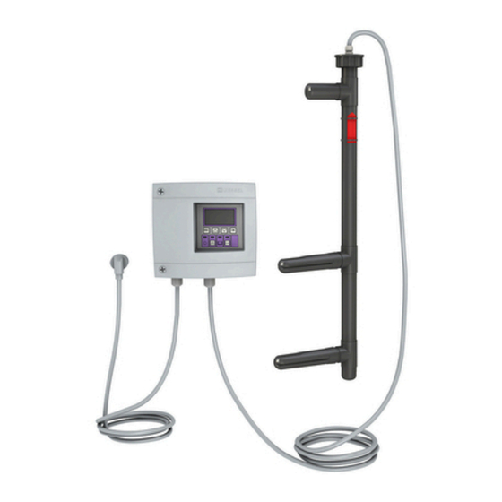
Schaltgerät
Schaltgerät
Fettschichtdicken-
Fettschichtdicken-
messgerät
messgerät
SonicControl
SonicControl
016-283
Advertisement
Chapters
Table of Contents

Subscribe to Our Youtube Channel
Related Manuals for Kessel SonicControl


Summary of Contents for Kessel SonicControl
- Page 1 Schaltgerät Schaltgerät Fettschichtdicken- Fettschichtdicken- messgerät messgerät SonicControl SonicControl 230 V 230 V Einbau- und Betriebsanleitung Einbau- und Betriebsanleitung Einbau- und Betriebsanleitung............... 2 Einbau- und Betriebsanleitung............... 2 Installation and operating instructions............19 Installation and operating instructions............19 Instructions de pose et d’utilisation.............. 37 Instructions de pose et d’utilisation..............
-
Page 2: Table Of Contents
Einbau- und Betriebsanleitung Liebe Kundin, lieber Kunde, als Premiumhersteller von innovativen Produkten für die Entwässerungstechnik bietet KESSEL ganzheitliche Systemlösun- gen und kundenorientierten Service. Dabei stellen wir höchste Qualitätsstandards und setzen konsequent auf Nachhaltig- keit - nicht nur bei der Herstellung unserer Produkte, sondern auch im Hinblick auf deren langfristigen Betrieb setzen wir uns dafür ein, dass Sie und Ihr Eigentum dauerhaft geschützt sind. -
Page 3: Hinweise Zu Dieser Anleitung
Hinweise zu dieser Anleitung Bei diesem Dokument handelt es sich um die Originalbetriebsanleitung. Die Sprache der Originalbetriebsanleitung ist Deutsch. Alle weiteren Sprachen dieser Anleitung sind eine Übersetzung der Originalbetriebsanleitung. Folgende Darstellungskonventionen erleichtern die Orientierung: Darstellung Erläuterung siehe Abbildung 1 Positionsnummer 5 von nebenstehender Abbildung Handlungsschritt in Abbildung Prüfen, ob Handbetrieb aktiviert wurde. -
Page 4: Sicherheit
Die Tätigkeiten am Schaltgerät sind auf: den Tausch der Batterien, das Anschließen nach Einbauanleitung und Anschlussplan beschränkt. Alle darüber hinausgehenden Arbeiten dürfen lediglich durch den KESSEL-Kundendienst oder einen Servicepartner der KESSEL SE + Co. KG durchgeführt werden. WARNUNG Spannungsführende Teile Bei Tätigkeiten an elektrischen Leitungen und Anschlüssen Folgendes beachten. -
Page 5: Technische Daten
Produktbeschreibung Das Schaltgerät überwacht zentimetergenau die Höhe der Fettschicht in KESSEL-Fettabscheidern EasyClean. PosNr. Baugruppe/Funktionselement Power-LED Alarmtaste und Alarm-LED ESC, Pfeiltasten, OK, Display LED Niveauüberschreitung Taste Handbetrieb (ohne Funktion) und LED Handbetrieb (1) Ruhewasser- Unterkante Auslauf ist das Niveau spiegel des Ruhewasserspiegels. -
Page 6: Montage
(0,75 mm ) bis max. 60 m verlängert werden. Sensorleitung Das Sensorkabel ist bauseits auf bis zu 60 m verlängerbar. Die Kabelverlängerung ist als IP67 auszuführen. KESSEL bietet hierfür passende Verlängerungssets an (Art.-Nr. 917871, 917872, 917873) Anschlüsse an Schaltgeräteunterseite ausführen Sensorkabel dürfen nicht in Kabel- oder Leiterbündeln... - Page 7 Weitere Anschlussmöglichkeiten Technische Hinweise Die LoRa-Platine (Art.-Nr. 72999) ermöglicht den drahtlosen Datentransfer zwischen dem SonicControl-Schaltgerät (ab 09/2021) und einer lokalen Gebäudeleittechnik oder einem zentral gehosteten Portal bzw. einer Cloudapplikation. Voraus- setzung ist ein Wide Area Network (WAN) mit der LoRa (long range) Architektur.
-
Page 8: Inbetriebnahme
Inbetriebnahme PosNr. Baugruppe/Funktionselement Power-LED Alarmtaste und Alarm-LED ESC, Pfeiltasten, OK, Display LED Niveauüberschreitung Taste Handbetrieb (ohne Funktion) und LED Handbetrieb Bei der Initialisierung werden folgende Eingaben erwartet: |Sprache| |Datum / Uhrzeit| |Produkttyp | |Nenngröße| |Kalibrierung| Sprache ► Landessprache mit den Pfeiltasten auswählen und mit OK bestätigen. - Page 9 3.1.2 Voralarm Schichtdicke Nach Einbau des Fettabscheiders diesen vollständig mit Wasser befüllen, Einbauhöhe überprüfen und ggf. korrigieren. Schaltgerät muss bei völlständig mit Wasser gefüllten Abscheider im Handbetrieb SonicControl „0cm“ anzeigen. 3.1 Parameter 3.1.7 Niveauabgleich Sollte keine mechanische Korrektur möglich sein, Änderung in durch- führen.
- Page 10 EasyClean Free (Freie Aufstellung) Artikelnummer 3.1.1 3.1.2 93002.01 /.02 /.11 /.12 /.21 /.22 /.31 /.32 93003.01 /.02 /.11 /.12 /.21 /.22 /.31 /.32 93004.01 /.02 /.11 /.12 /.21 /.22 /.31 /.32 93007.01 /.02 /.11 /.12 /.21 /.22 /.31 /.32 93010.01 /.02 /.11 /.12 /.21 /.22 /.31 /.32 93015-01-L/ 93015-01-R/ 93015-06 Standard 93020-01-L/ 93020-01-R/ 93020-06...
- Page 11 EasyClean Free (Freie Aufstellung) Artikelnummer 3.1.1 3.1.2 93002.01/DS, .02/DS, .31/DS, .32/DS 93003.01/DS, .02/DS, .31/DS, .32/DS 93004.01/DS, .02/DS, .31/DS, .32/DS 93007.01/DS, .02/DS, .31/DS, .32/DS 93010.01/DS, .02/DS, .31/DS, .32/DS 93015-01-DS-L/ 93015-01-DS-R/ 93015-06-DS 93020-01-DS-L/ 93020-01-DS-R/ 93020-06-DS 93025-06-DS 93030-06-DS 93035.01/DS 93040.01/DS 93050.01/DS 93002.01/DSP, .02/DSP 93003.01/DSP, .02/DSP 93004.01/DSP, .02/DSP 93007.01/DSP, .02/DSP...
- Page 12 EasyClean Free (Freie Aufstellung) Artikelnummer 3.1.1 3.1.2 93002.01/PVS, .02/PVS 93003.01/PVS, .02/PVS 93004.01/PVS, .02/PVS 93007.01/PVS, .02/PVS 93010.01/PVS, .02/PVS 93015-01-PVS-L/93015-01-PVS-R/ 93015-06-PVS Auto Mix & Pump 93020-01-PVS-L/93020-01-PVS-R/ 93020-06-PVS 93025-06-PVS 93030-06-PVS 93035.01/PVS 93040.01/PVS 93050.01/PVS Abstand Oberkante unterer Finger zu Unterkante Auslauf (Wasserlinie) = 50 cm EasyClean ground (Erdeinbau) Artikelnummer 3.1.1...
- Page 13 EasyClean ground (Erdeinbau) Artikelnummer 3.1.1 3.1.2 93002/120 B und D -PVS-TS 50 cm 93002/170 B und D -PVS-TS 93004/120 B und D -PVS-TS 50 cm 93004/170 B und D -PVS-TS Auto Mix & Pump 93007/120 B und D -PVS-TS 50 cm 93007/170 B und D -PVS-TS 93010/120 B und D -PVS-TS 50 cm...
-
Page 14: Betrieb
Betrieb Betriebsarten Das vorliegende KESSEL-Schaltgerät verfügt, sobald es initialisiert ist, über die folgenden Betriebszustände. Automatikbetrieb (Normalbetrieb) Das Schaltgerät überwacht und steuert die angeschlossenen elektronischen Kom- ponenten ohne Einschränkung. Handbetrieb Das Schaltgerät sendet einen zusätzlichen Scan-Impuls und ermittelt die aktuelle Schichtdicke und vermerkt sie im Logbuch. - Page 15 2 Wartung - Wartungsrelevante Tätigkeiten (z. B. Wartungs- termin) Ordnungszahl 3 Einstellungen - Parameter wie Alarmschichtdicke, Datum/ Uhrzeit, Norm, Nenngröße), Systemsprache ändern, potenti- alfreier Kontakt 4 Kommunikation - Konfiguration des Kommunikationstyps (SMS, LoRaWAN) Menütexte SonicControl Systeminfo Datenübertragung 0.1.1 Software-Update 0.1.1.1 Software-Update (SG) 0.1.1.2 Modul-Update (EWP) 0.1.1.3...
- Page 16 Schichtdicke 2.1.3 Potentialfreier Kontakt 2.1.4 Externer Signalgeber Wartungsintervall Wartungstermin Passwort: 2.3.1 Letzte Wartung dd.mm.yy 1000 hh:mm:ss 2.3.2 Nächste Wartung Wartung durchgeführt Kalibrierung SonicControl Sensordiagnose Einstellungen Parameter 3.1.1 Alarm Schichtdicke Passwort: 1000 3.1.2 Voralarm Schichtdicke 3.1.3 Alarm-Temperatur 3.1.4 Messbereichsanfang 3.1.5 Messbereichsende 3.1.6...
-
Page 17: Wartung
Bei jeder Entsorgung ist die Sensors mit warmen/heißem Wasser reinigen. Bei Fettabscheideranlagen KESSEL EasyClean Auto Mix, Mix & Pump- und Auto Mix & Pump kann auf die Reinigung des Sensors bis zur nächsten Wartung verzichtet werden, wenn der Abscheider mit warmem Wasser gereinigt wird. -
Page 18: Hilfe Bei Störungen
Hilfe bei Störungen Fehler/Meldungen im Display Fehler und Alarme werden über den potentialfreien Kontakt weitergeleitet. Anzeige Ursache Abhilfemaßnahme |Keine Ruhe- Sensor falsch verbaut Einbausituation prüfen phase erkannt| Messintervall während Betriebsphase Messintervall anpassen Schlamm überdeckt Sensor Abscheider bei erhöhter Schlammschicht entsorgen Schwebstoffe/Grobstoffe Grobfang vorschalten Sensor konnte die letzten 3 Tage keinen gül-... - Page 19 Installation and operating instructions Dear Customer, As a premium manufacturer of innovative products for draining technology, KESSEL offers integrated system solutions and customer-oriented service. In doing so, we set the highest quality standards and focus firmly on sustainability - not only with the manufacturing of our products, but also with regard to their long-term operation and we strive to ensure that you and your property are protected over the long term.
-
Page 20: Notes On This Manual
Notes on this manual This document is a translation of the original operating instructions. The original operating instructions are written in German. All other language versions of these instructions are a translation of the original operating instructions. The following conventions make it easier to navigate the manual: Symbol Explanation See Figure 1... -
Page 21: Safety
Work on the control unit is restricted to: replacing the batteries, Connection in accordance with the installation instructions and wiring diagram. All work extending beyond this may only be carried out by KESSEL customer service or a KESSEL SE + Co. KG service partner. WARNING Live parts Heed the following points when working on electrical cables and connections. -
Page 22: Technical Data
Product description The control unit monitors the depth of the grease layer in KESSEL EasyClean grease separators to the nearest cen- timetre. Item Assembly/functional element Power LED Alarm button and alarm LED ESC, Arrow buttons, OK, Display Level exceedance LED... - Page 23 General technical data Connection type Schuko earthed safety plug Installation and operating instructions 23 / 112...
-
Page 24: Installation
(0.75 mm Sensor cable The sensor cable can be extended up to 60 m on site. The cable extension must have an IP67 rating. KESSEL has suitable extension sets for this (art. no. 917871, 917872, 917873) Make the connections to the underside of the control units Sensor cables may not be laid together with other electric circuits in cable or conductor bundles. - Page 25 Technical notes The LoRa printed circuit board (art. no. 72999) enables wireless data transfer between the SonicControl control unit (from 09/2021) and a local building control system a centrally hosted portal or a cloud application. This requires a wide area network (WAN) with the LoRa (long range) architecture.
-
Page 26: Commissioning
Commissioning Item Assembly/functional element Power LED Alarm button and alarm LED ESC, Arrow buttons, OK, Display Level exceedance LED Manual Operation button (no function) and Man- ual Operation LED During initialisation, the following input is expected: |Language| |Date / time| |Product type | |Nominal size | |Calibration|... - Page 27 3.1.2 Pre-alarm layer thickness After installing the grease separator, fill it completely with water, check the installation height and correct if necessary. When the separator is completely filled with water, the control unit must display „0cm“ when the SonicControl is in manual operation.
- Page 28 EasyClean Free (free-standing installation) Article number 3.1.1 3.1.2 93002.01 /.02 /.11 /.12 /.21 /.22 /.31 /.32 93003.01 /.02 /.11 /.12 /.21 /.22 /.31 /.32 93004.01 /.02 /.11 /.12 /.21 /.22 /.31 /.32 93007.01 /.02 /.11 /.12 /.21 /.22 /.31 /.32 93010.01 /.02 /.11 /.12 /.21 /.22 /.31 /.32 93015-01-L/ 93015-01-R/ 93015-06 Standard...
- Page 29 EasyClean Free (free-standing installation) Article number 3.1.1 3.1.2 93002.01/DS, .02/DS, .31/DS, .32/DS 93003.01/DS, .02/DS, .31/DS, .32/DS 93004.01/DS, .02/DS, .31/DS, .32/DS 93007.01/DS, .02/DS, .31/DS, .32/DS 93010.01/DS, .02/DS, .31/DS, .32/DS 93015-01-DS-L/ 93015-01-DS-R/ 93015-06-DS 93020-01-DS-L/ 93020-01-DS-R/ 93020-06-DS 93025-06-DS 93030-06-DS 93035.01/DS 93040.01/DS 93050.01/DS 93002.01/DSP, .02/DSP 93003.01/DSP, .02/DSP 93004.01/DSP, .02/DSP 93007.01/DSP, .02/DSP...
- Page 30 EasyClean Free (free-standing installation) Article number 3.1.1 3.1.2 93002.01/PVS, .02/PVS 93003.01/PVS, .02/PVS 93004.01/PVS, .02/PVS 93007.01/PVS, .02/PVS 93010.01/PVS, .02/PVS 93015-01-PVS-L/93015-01-PVS-R/ 93015-06-PVS Auto Mix & Pump 93020-01-PVS-L/93020-01-PVS-R/ 93020-06-PVS 93025-06-PVS 93030-06-PVS 93035.01/PVS 93040.01/PVS 93050.01/PVS Distance between the upper edge of the lower finger and the lower edge of the outlet (water line) = 50 cm EasyClean ground (underground installation) Article number 3.1.1...
- Page 31 EasyClean ground (underground installation) Article number 3.1.1 3.1.2 93002/120 B and D -PVS-TS 50 cm 93002/170 B and D -PVS-TS 93004/120 B and D -PVS-TS 50 cm 93004/170 B and D -PVS-TS Auto Mix & Pump 93007/120 B and D -PVS-TS 50 cm 93007/170 B and D -PVS-TS 93010/120 B and D -PVS-TS...
-
Page 32: Operation
Operation Operating modes As soon as it is initialised, this KESSEL control unit has the following operating states. Automatic operation (normal opera- The control unit monitors and controls the connected electronic components with- tion) out limitation. Manual operation The control unit sends an additional scan pulse and determines the current layer thickness, and then notes it in the log book. - Page 33 3 Settings - parameters such as alarm layer thickness, date/time, standard, nominal size), change system lan- guage, potential-free contact 4 Communication - configuration of the type of communica- tion (SMS, LoRaWAN) SonicControl menu texts System info Data exchange 0.1.1 Software update 0.1.1.1...
- Page 34 Ext. audible alarm Maintenance interval Maintenance date, password: 2.3.1 Last maintenance dd.mm.yy 1000 hh:mm:ss 2.3.2 Next maintenance Maintenance done Calibration of SonicControl Sensor diagnosis Settings Parameters 3.1.1 Alarm layer thickness Password: 1000 3.1.2 Pre-alarm layer thickness 3.1.3 Alarm temperature 3.1.4 Start of measuring range 3.1.5...
-
Page 35: Maintenance
The sensor must be cleaned with warm/hot water with each disposal. In the case of the KESSEL EasyClean Auto Mix, Mix & Pump- and Auto Mix & Pump grease separators, the clean- ing of the sensor can be omitted until the next maintenance if the separator is cleaned with warm water. If necessary (heavy soiling of the sensor due to highly hardening grease), carry out cleaning at each disposal Check the connection cables and sensor for damage. -
Page 36: Troubleshooting
Troubleshooting Errors/messages in the display Errors and alarms are forwarded via the potential-free contact. Display Cause Remedial measure |No rest phase Sensor installed incorrectly Check the installation situation detected| Measurement interval during the operating Adjust the measurement interval phase Dispose of separator contents in case of Sludge covers sensor increased sludge layer Suspended materials/coarse materials... - Page 37 Instructions de pose et d’utilisation Chère cliente, cher client, En qualité de producteur de pointe de produits novateurs dans le domaine de la technique d’assainissement, KESSEL pro- pose des réponses systématiques globales et un service orienté aux besoins de la clientèle. Nous misons simultanément sur les normes de qualité...
-
Page 38: Informations Spécifiques Aux Présentes Instructions
Informations spécifiques aux présentes instructions Ce document est la traduction de l'original du mode d’emploi. L’original a été rédigé en allemand. Toutes les autres versions linguistiques de ce mode d’emploi sont des traductions de l’original. Les conventions de représentation suivantes facilitent l’orientation : Représentation Explication voir figure 1... -
Page 39: Sécurité
Tous les travaux dépassant ce cadre sont réservés au domaine de compétence du service après-vente KESSEL ou d'un partenaire du service après-vente de KESSEL SE + Co. KG. -
Page 40: Caractéristiques Techniques
Description du produit Le gestionnaire surveille la hauteur de la couche de graisse dans le séparateur à graisses KESSEL EasyClean au centi- mètre près. N° Sous-ensemble/élément fonctionnel pos. Diode de puissance Touche d'alarme et diode d'alarme ESC, Flèches, OK, Écran Diode de dépassement du niveau... - Page 41 Caractéristiques techniques générales Dimensions (LxlxH), mm 208x194x70 Type de raccord Fiche à contact de protection Instructions de pose et d’utilisation 41 / 112...
-
Page 42: Montage
Le câble du capteur peut être rallongé jusqu'à 60 m par le client. La rallonge de câble doit présenter un niveau de protection IP67. KESSEL propose à cet effet des kits de rallonge adaptés (réf. 917871, 917872, 917873) Effectuer les raccordements sur la face inférieure du gestionnaire Il est interdit de poser les câbles des capteurs ensemble... - Page 43 Note technique La carte LoRa (réf. 72999) permet le transfert de données sans fil entre le gestionnaire du SonicControl (à partir de 09/2021) et un système de gestion technique du bâtiment, un portail centralisé ou une application dématérialisée (cloud). Cela néces- site un réseau étendu (WAN) avec l'architecture LoRa (longue portée).
-
Page 44: Mise En Service
Mise en service N° Sous-ensemble/élément fonctionnel pos. Diode de puissance Touche d'alarme et diode d'alarme ESC, Flèches, OK, Écran Diode de dépassement du niveau Touche Mode manuel (sans fonction) et diode mode manuel L'initialisation impose de procéder aux saisies suivantes : |Langue| |Date / Heure| |Type de produit |... - Page 45 Paramètres EasyClean free A Paramètres Spé- 12,5 cial Alarme d'épais- seur de couche (cm) Préalarme d'épaisseur de couche (cm) Température d'alarme (°C) Début de la plage de mesure (cm) Fin de la plage de mesure (cm) Intervalle de mesure heure de début Intervalle de mesure heure de...
- Page 46 Après la pose, remplir complètement le séparateur à graisses d'eau, contrôler la profondeur de pose et la corriger au besoin. Lorsque le séparateur est entièrement rempli d'eau, le gestionnaire doit afficher Sonic Control « 0 cm » en mode manuel. 3.1 Paramètres Si aucune correction mécanique n'est possible, procéder à...
- Page 47 EasyClean Free (pose hors-sol à l'abri du gel) N° de référence 3.1.1 3.1.2 93002.01/DS, .02/DS, .31/DS, .32/DS 93003.01/DS, .02/DS, .31/DS, .32/DS 93004.01/DS, .02/DS, .31/DS, .32/DS 93007.01/DS, .02/DS, .31/DS, .32/DS 93010.01/DS, .02/DS, .31/DS, .32/DS 93015-01-DS-L/ 93015-01-DS-R/ 93015-06-DS 93020-01-DS-L/ 93020-01-DS-R/ 93020-06-DS 93025-06-DS 93030-06-DS 93035.01/DS 93040.01/DS...
- Page 48 EasyClean Free (pose hors-sol à l'abri du gel) N° de référence 3.1.1 3.1.2 93002.01/PVS, .02/PVS 93003.01/PVS, .02/PVS 93004.01/PVS, .02/PVS 93007.01/PVS, .02/PVS 93010.01/PVS, .02/PVS 93015-01-PVS-L/93015-01-PVS-R/ 93015-06-PVS Auto Mix & Pump 93020-01-PVS-L/93020-01-PVS-R/ 93020-06-PVS 93025-06-PVS 93030-06-PVS 93035.01/PVS 93040.01/PVS 93050.01/PVS Distance entre le bord supérieur du doigt inférieur du capteur et le bord inférieur de la sortie (niveau de l’eau) = 50 cm EasyClean ground (pose enterrée) N°...
- Page 49 EasyClean ground (pose enterrée) N° de référence 3.1.1 3.1.2 93002/120 B et D -PVS-TS 50 cm 93002/170 B et D -PVS-TS 93004/120 B et D -PVS-TS 50 cm 93004/170 B et D -PVS-TS Auto Mix & Pump 93007/120 B et D -PVS-TS 50 cm 93007/170 B et D -PVS-TS 93010/120 B et D -PVS-TS...
-
Page 50: Fonctionnement
Fonctionnement Modes de fonctionnement Une fois initialisé, ce gestionnaire KESSEL présente les états de fonctionnement suivants. Mode automatique (fonctionnement Le gestionnaire surveille et contrôle sans limitation les composants électroniques normal) raccordés. Mode manuel Le gestionnaire envoie une impulsion de balayage supplémentaire et détermine l'épaisseur actuelle de la couche et l'enregistre dans le journal d'exploitation. - Page 51 3 Configurations - Paramètres, comme Épaisseur de la couche d'alarme, Date/heure, Norme, Taille nominale), Changer la langue du système, Contact sec 4 Communication - Configuration du type de communica- tion (Texto, LoRaWAN) Textes de menu SonicControl Info système Transmission des données 0.1.1 Mise à jour du logiciel 0.1.1.1...
- Page 52 Date de maintenance mot de 2.3.1 Maintenance précédente jj.mm.aa passe : 1000 hh:mm:ss 2.3.2 Maintenance suivante Maintenance effectuée Calibrage du SonicControl Diagnostic capteur Configurations Paramètres 3.1.1 Alarme d'épaisseur de couche Mot de passe : 1000 3.1.2 Préalarme d'épaisseur de couche 3.1.3...
-
Page 53: Maintenance
Vous pouvez renoncer au nettoyage du capteur jusqu'à la prochaine intervention de maintenance des séparateurs à graisses KESSEL EasyClean Auto Mix, Mix & Pump- et Auto Mix & Pump, étant donné que ces types de séparateur sont nettoyés à l'eau chaude. Au besoin (fort encrassement du capteur par des graisses durcies), effectuer un net- toyage à... -
Page 54: Aide En Cas De Panne
Aide en cas de panne Erreurs/messages à l’écran Les erreurs et alarmes sont transmises par le contact sec. Afficher Cause Remède |Pas de phase Capteur mal installé Vérifier la situation de montage de repos iden- Intervalle de mesure pendant la phase de Adapter l’intervalle de mesure tifiée| fonctionnement... - Page 55 Défaut Cause Remède Échec de l’envoi du texto Réception insuffisante Vérifier l’intensité des signaux en général Si aucune réception n'est possible avec le signal existant, changer de modem Instructions de pose et d’utilisation 55 / 112...
- Page 56 Cara cliente, caro cliente, in qualità di produttore premium di prodotti innovativi per la tecnica di drenaggio, KESSEL offre soluzioni di sistema integrate e un servizio orientato al cliente. Puntiamo sui massimi standard qualitativi e ci impegniamo coerentemente per la sosteni- bilità...
-
Page 57: Indicazioni Sulle Presenti Istruzioni
Indicazioni sulle presenti istruzioni Il presente documento costituisce le istruzioni per l’uso originali. La lingua delle istruzioni per l’uso originali è il tedesco. Tutte le versioni in altre lingue di queste istruzioni costituiscono delle traduzioni. Le seguenti convenzioni illustrative semplificano l’orientamento: Simbolo Spiegazione vedere figura 1... -
Page 58: Sicurezza
Tutti i lavori diversi da quelli elencati devono essere eseguiti esclusivamente dal servizio clienti KESSEL o da un partner di assistenza della KESSEL SE + Co. KG. -
Page 59: Dati Tecnici
Descrizione del prodotto La centralina monitora con precisione al centimetro l’altezza dello strato di grasso nei separatori di grassi KESSEL Easy- Clean. Pos. n Gruppo costruttivo/elemento funzionale ° LED di alimentazione Tasto di allarme e LED d’allarme ESC, tasti-freccia, OK,... - Page 60 Dati tecnici generali Dimensioni (Lu x La x Pr), mm 208x194x70 Tipo di collegamento Presa tipo Schuko 60 / 112 Istruzioni per l’installazione e l’uso...
-
Page 61: Montaggio
Il cavo del sensore può essere prolungato in loco fino a 60 m. Il prolungamento del cavo deve essere realizzato nel rispetto della classe IP67. KESSEL offre gli appositi set di prolunga (codice articolo 917871, 917872, 917873) Realizzazione dei collegamenti sulla parte inferiore della centralina I cavi del sensore non devono essere posati in fasci di cavi o di conduttori unitamente ad altri circuiti elettrici. - Page 62 Altre possibilità di collegamento Note tecniche La scheda LoRA (cod. art. 72999) consente il trasferimento dati via wireless tra la centralina SonicControl (dal 09/2021) e un sistema di controllo dell’edificio locale, un portale ospitato centralmente oppure un’applicazione cloud. Ciò richiede una rete WAN (Wide Area Network) con architettura LoRA (long range).
-
Page 63: Messa In Funzione
Messa in funzione Pos. n Gruppo costruttivo/elemento funzionale ° LED di alimentazione Tasto di allarme e LED d’allarme ESC, tasti-freccia, OK, Display LED superamento del livello Tasto di funzionamento manuale (senza fun- zione) e LED di funzionamento manuale Al momento dell’inizializzazione vengono richieste le seguenti immissioni: |Lingua| |Data / Ora|... - Page 64 Dopo l’installazione del separatore di grassi, riempirlo completamente di acqua, controllare l’altezza di installazione e cor- reggere se necessario. La centralina - con l’impianto di separazione completamente pieno d’acqua in funzionamento manuale - deve indicare SonicControl “0cm”. 3.1 Parametri Qualora non dovesse essere possibile alcuna correzione meccanica, eseguire una modifica alla voce 3.1.7 Calibrazione livello...
- Page 65 EasyClean Free (installazione in appoggio) Codice articolo 3.1.1 3.1.2 93002.01/.02/.11/.12/.21/.22/.31/.32 93003.01/.02/.11/.12/.21/.22/.31/.32 93004.01/.02/.11/.12/.21/.22/.31/.32 93007.01/.02/.11/.12/.21/.22/.31/.32 93010.01/.02/.11/.12/.21/.22/.31/.32 93015-01-L/93015-01-R/93015-06 Standard 93020-01-L/93020-01-R/93020-06 93025-06 93030-06 93035.01 93040.01 93050.01 93002-R 93002.00/D1-R Modular Stan- dard / Modu- 93003-R lar Direct 93003.00/D1-R (in 2 parti) 93004-R 93004.00/D1-R 93002.01 D/.02 D/.11 D/.12 D/.21 D/.22 D/.31 D/.32 D 93003.01 D/.02 D/.11 D/.12 D/.21 D/.22 D/.31 D/.32 D 93004.01 D/.02 D/.11 D/.12 D/.21 D/.22 D/.31 D/.32 D 93007.01 D/.02 D/.11 D/.12 D/.21 D/.22 D/.31 D/.32 D...
- Page 66 EasyClean Free (installazione in appoggio) Codice articolo 3.1.1 3.1.2 93002.01/DS, .02/DS, .31/DS, .32/DS 93003.01/DS, .02/DS, .31/DS, .32/DS 93004.01/DS, .02/DS, .31/DS, .32/DS 93007.01/DS, .02/DS, .31/DS, .32/DS 93010.01/DS, .02/DS, .31/DS, .32/DS 93015-01-DS-L/93015-01-DS-R/93015-06-DS 93020-01-DS-L/93020-01-DS-R/93020-06-DS 93025-06-DS 93030-06-DS 93035.01/DS 93040.01/DS 93050.01/DS 93002.01/DSP, .02/DSP 93003.01/DSP, .02/DSP 93004.01/DSP, .02/DSP 93007.01/DSP, .02/DSP 93010.01/DSP, .02/DSP...
- Page 67 EasyClean Free (installazione in appoggio) Codice articolo 3.1.1 3.1.2 93002.01/PVS, .02/PVS 93003.01/PVS, .02/PVS 93004.01/PVS, .02/PVS 93007.01/PVS, .02/PVS 93010.01/PVS, .02/PVS 93015-01-PVS-L/93015-01-PVS-R/93015-06-PVS Auto Mix & Pump 93020-01-PVS-L/93020-01-PVS-R/93020-06-PVS 93025-06-PVS 93030-06-PVS 93035.01/PVS 93040.01/PVS 93050.01/PVS Distanza tra il bordo superiore dello stelo inferiore al bordo inferiore dell’uscita (linea dell’acqua) = 50 cm EasyClean ground (installazione interrata) Codice articolo 3.1.1...
- Page 68 EasyClean ground (installazione interrata) Codice articolo 3.1.1 3.1.2 93002/120 B e D -PVS-TS 50 cm 93002/170 B e D -PVS-TS 93004/120 B e D -PVS-TS 50 cm 93004/170 B e D -PVS-TS Auto Mix & Pump 93007/120 B e D -PVS-TS 50 cm 93007/170 B e D -PVS-TS 93010/120 B e D -PVS-TS...
-
Page 69: Funzionamento
Funzionamento Tipi di funzionamento La presente centralina KESSEL dispone degli stati di funzionamento seguenti immediatamente dopo l’inizializzazione. Funzionamento automatico (funziona- La centralina monitora e comanda i componenti elettronici collegati senza mento normale) limitazione. Funzionamento manuale La centralina invia un impulso di scansione supplementare e determina lo spes- sore dello strato attuale e lo registra nel diario d’esercizio. - Page 70 3 Impostazioni – parametri come spessore dello strato d’al- larme, data/ora, norma, dimensioni nominali), modifica della lingua di sistema, contatto a potenziale zero 4 Comunicazione – configurazione del tipo di comunica- zione (SMS, LoRaWAN) Testi del menu SonicControl Informazioni di sistema Trasferimento dati 0.1.1 Aggiornamento software 0.1.1.1...
- Page 71 Intervallo di manutenzione Password impostazione della 2.3.1 Ultima manutenzione gg.mm.aa scadenza di manutenzione: hh:mm:ss 1000 2.3.2 Prossima manutenzione Manutenzione eseguita Calibrazione SonicControl Diagnosi sensore Impostazioni Parametri 3.1.1 Allarme dello spessore dello strato Password: 1000 3.1.2 Preallarme dello spessore dello strato 3.1.3 Temperatura di allarme 3.1.4...
-
Page 72: Manutenzione
In presenza di danni riconoscibili, il sensore deve essere messo immediatamente fuori servizio ed essere fatto sosti- tuire da un elettricista specializzato. Dopo lo svuotamento, riempire l’impianto di separazione con acqua pulita. |2.6 Calibrazione SonicControl| Eseguire nuovamente la calibrazione ( ) se il sensore è stato ruotato o spo- stato. -
Page 73: Aiuto In Caso Di Disturbi
Aiuto in caso di disturbi Errori / messaggi sul display Errori e allarmi vengono inoltrati tramite il contatto a potenziale zero. Visualizzazione Causa Rimedio |Nessuna fase Sensore montato in modo errato Controllare la situazione di posa statica ricono- Intervallo di misurazione durante la fase di Adattare l’intervallo di misurazione sciuta| funzionamento... - Page 74 Errore Causa Misura correttiva Invio di SMS fallito Ricezione lacunosa Controllare la potenza del segnale di base Se la ricezione non è possibile ma il segnale è presente, sostituire il modem 74 / 112 Istruzioni per l’installazione e l’uso...
- Page 75 Inbouw- en bedieningshandleiding Beste klant, Als premium fabrikant van innovatieve producten voor de afwateringstechniek biedt KESSEL totale systeemoplossingen en klantgerichte service. Wij stellen hierbij maximale kwaliteitsnormen en zetten consequent in op duurzaamheid, niet alleen bij de productie van onze producten, maar ook met het oog op hun langdurige gebruik zetten wij ons in voor een permanente bescherming van u en uw eigendom.
-
Page 76: Informatie Over Deze Handleiding
Informatie over deze handleiding Dit document bevat de originele bedieningshandleiding. De handleiding is in het Duits geschreven. Alle teksten in andere talen in deze handleiding zijn vertalingen van de oorspronkelijke Duitse tekst. De handleiding wordt verduidelijkt met de volgende visuele conventies: Afbeelding Uitleg zie afbeelding 1... -
Page 77: Veiligheid
De activiteiten bij de besturingskast zijn tot: het vervangen van de batterijen, het aansluiten volgens de inbouwhandleiding en het aansluitschema beperkt. Alle verdergaande werkzaamheden mogen enkel door de KESSEL-klantenservice of een servicepartner van KESSEL SE + Co. KG worden uitgevoerd. WAARSCHUWING Spanningvoerende delen Bij werkzaamheden aan de elektrische bekabeling en aansluitingen het onderstaande in acht nemen. -
Page 78: Technische Gegevens
Productomschrijving De besturingskast bewaakt de dikte van de vetlaag in de KESSEL-vetafscheider EasyClean tot de centimeter nauw- keurig. Num- Module / functioneel element Stroomled Alarmtoets en alarmled ESC, pijltjestoetsen, OK, Scherm Led niveau-overschrijding Toets (zonder functie) en led voor de handbedie-... - Page 79 Algemene technische gegevens Aansluittype Randaardestekker Inbouw- en bedieningshandleiding 79 / 112...
-
Page 80: Monteren
(0,75 mm wordt gebruikt. Sensorkabel De sensorkabel kan op locatie tot 60 m worden verlengd. De kabelverlenging moet voldoen aan IP67-criteria. KESSEL biedt hier bijpassende verlengsets (art.nr. 917871, 917872 en 917873) voor aan. Aansluitingen aan de onderkant van de besturingskast uitvoeren De sensorkabels mogen niet samen met andere stroomcir- cuits in kabel- of leidingbundels worden gelegd. - Page 81 Overige aansluitmogelijkheden Technische aanwijzing De LoRa printplaat (Art.-Nr. 72999) maakt draadloos gegevensoverdracht mogelijk tussen de SonicControl besturingskast (vanaf 09/2021) en een lokaal gebouwbeheerssysteem of een centraal gecontroleerd portaal zoals bijv. een cloudapplicatie. Hiervoor dient een “wide area network” (WAN) aanwezig te zijn met de LoRa (long range) architectuur.
-
Page 82: Inbedrijfstelling
Inbedrijfstelling Num- Module / functioneel element Stroomled Alarmtoets en alarmled ESC, pijltjestoetsen, OK, Scherm Led niveau-overschrijding Toets (zonder functie) en led voor de handbedie- ning Bij de initialisatie wordt de volgende invoer verwacht: |Taal| |Datum/tijd| |Producttype| |Nominale grootte| |Kalibratie| Taal ►... - Page 83 3.1.2 Vooralarm laagdikte Vul de vetafscheider na het inbouwen volledig met water, en controleer en corrigeer eventueel de inbouwdiepte. Als de afscheider in de handmatige bediening volledig met water is gevuld, moet de besturingskast SonicControl “0cm” aangeven. 3.1 Parameters 3.1.7 Niveaucompensatie...
- Page 84 EasyClean free (vrije opstelling) Artikelnummer 3.1.1 3.1.2 93002.01 /.02 /.11 /.12 /.21 /.22 /.31 /.32 93003.01 /.02 /.11 /.12 /.21 /.22 /.31 /.32 93004.01 /.02 /.11 /.12 /.21 /.22 /.31 /.32 93007.01 /.02 /.11 /.12 /.21 /.22 /.31 /.32 93010.01 /.02 /.11 /.12 /.21 /.22 /.31 /.32 93015-01-L/ 93015-01-R/ 93015-06 Standaard 93020-01-L/ 93020-01-R/ 93020-06...
- Page 85 EasyClean free (vrije opstelling) Artikelnummer 3.1.1 3.1.2 93002.01/DS, .02/DS, .31/DS, .32/DS 93003.01/DS, .02/DS, .31/DS, .32/DS 93004.01/DS, .02/DS, .31/DS, .32/DS 93007.01/DS, .02/DS, .31/DS, .32/DS 93010.01/DS, .02/DS, .31/DS, .32/DS 93015-01-DS-L/ 93015-01-DS-R/ 93015-06-DS 93020-01-DS-L/ 93020-01-DS-R/ 93020-06-DS 93025-06-DS 93030-06-DS 93035.01/DS 93040.01/DS 93050.01/DS 93002.01/DSP, .02/DSP 93003.01/DSP, .02/DSP 93004.01/DSP, .02/DSP 93007.01/DSP, .02/DSP...
- Page 86 EasyClean free (vrije opstelling) Artikelnummer 3.1.1 3.1.2 93002.01/PVS, .02/PVS 93003.01/PVS, .02/PVS 93004.01/PVS, .02/PVS 93007.01/PVS, .02/PVS 93010.01/PVS, .02/PVS 93015-01-PVS-L/93015-01-PVS-R/ 93015-06-PVS Auto Mix & Pump 93020-01-PVS-L/93020-01-PVS-R/ 93020-06-PVS 93025-06-PVS 93030-06-PVS 93035.01/PVS 93040.01/PVS 93050.01/PVS Afstand bovenkant onderste vinger tot onderkant uitloop (waterlijn) = 50 cm EasyClean ground (aardinbouw) Artikelnummer 3.1.1...
- Page 87 EasyClean ground (aardinbouw) Artikelnummer 3.1.1 3.1.2 93002/120 B en D -PVS-TS 50 cm 93002/170 B en D -PVS-TS 93004/120 B en D -PVS-TS 50 cm 93004/170 B en D -PVS-TS Auto Mix & Pump 93007/120 B en D -PVS-TS 50 cm 93007/170 B en D -PVS-TS 93010/120 B en D -PVS-TS 50 cm...
-
Page 88: Gebruik
Gebruik Soorten bedrijf Deze KESSEL-besturingskast beschikt na initialisatie over de volgende bedrijfstoestanden. Automatisch bedrijf (normale werking) De besturingskast bewaakt en stuurt de aangesloten elektrische onderdelen zon- der beperking aan. Handbediening De besturingskast verstuurt een aanvullende scanimpuls, bepaalt de huidige laag- dikte en registreert de dikte in het bedrijfslogboek. - Page 89 (bijvoorbeeld de onderhoudsdatum) (Sub)menunummer 3 Instellingen : parameters zoals de alarmlaagdikte, datum/ tijd, standaard, nominale grootte), de systeemtaal wijzigen, potentiaalvrij contact 4 Communicatie : configuratie van het soort communicatie (sms, LoRaWAN) Menuteksten SonicControl Systeeminfo Gegevensoverdracht 0.1.1 Software-update 0.1.1.1 Software-update (BK) 0.1.1.2...
- Page 90 2.1.3 Potentiaalvrij contact 2.1.4 Externe signaalsensor Onderhoudsinterval Wachtwoord onderhoudsda- 2.3.1 Laatste onderhoud dd.mm.yy tum: 1000 hh:mm:ss 2.3.2 Volgende onderhoud Onderhoud uitgevoerd Kalibratie SonicControl Sensordiagnose Instellingen Parameters 3.1.1 Alarm laagdikte Wachtwoord: 1000 3.1.2 Vooralarm laagdikte 3.1.3 Alarmtemperatuur 3.1.4 Begin meetbereik 3.1.5 Einde meetbereik 3.1.6...
-
Page 91: Onderhoud
Bij elke lediging moet de sensor met warm/heet water worden gereinigd. Bij vetafscheiders KESSEL EasyClean Auto Mix, Mix & Pump en Auto Mix & Pump kan het reinigen van de sensor tot het volgende onderhoud worden uitgesteld, mits de afscheider met warm water is gereinigd. Zo nodig (bij sterke ver- ontreiniging van de sensor door sterk uithardende vetten) de reiniging bij elke lediging uitvoeren. -
Page 92: Hulp Bij Storingen
Hulp bij storingen Fouten/meldingen op het scherm Fouten en alarmen worden via het potentiaalvrij contact doorgestuurd. Display Oorzaak Remedie |Geen rustfase Sensor verkeerd ingebouwd Inbouwsituatie controleren herkend| Meetinterval tijdens gebruiksfase Meetinterval aanpassen Sensor met slib bedekt Afscheider bij verdikte sliblaag ledigen Zwevende/grove stoffen Filter voor grove deeltjes voor de afscheider plaatsen... - Page 93 Instrukcja zabudowy i obsługi Szanowna Klientko, Szanowny Kliencie, jako producent najwyższej klasy innowacyjnych produktów z zakresu techniki odwadniania firma KESSEL oferuje komplek- sowe rozwiązania systemowe i serwis odpowiadający potrzebom klientów. Stawiamy sobie najwyższe standardy jakościowe i konsekwentnie stawiamy na trwałość – nie tylko podczas produkcji naszych urządzeń, lecz również w zakresie ich długo- trwałego użytkowania dbamy o to, by stale gwarantowane było bezpieczeństwo użytkownika i jego mienia.
-
Page 94: Wskazówki Dotyczące Niniejszej Instrukcji
Wskazówki dotyczące niniejszej instrukcji Niniejszy dokument jest oryginalną instrukcją obsługi. Oryginalna instrukcja obsługi jest napisana w języku niemieckim. Wszystkie inne wersje językowe tej instrukcji są tłumaczeniem oryginalnej instrukcji obsługi. Poniższe formy oznaczeń ułatwiają orientację: Oznaczenie Objaśnienie patrz rysunek 1 Numer pozycji 5 na rysunku obok Krok postępowania na rysunku Sprawdzić, czy aktywowana została obsługa Warunek postępowania... -
Page 95: Bezpieczeństwo
Prace przy urządzeniu sterującym ograniczają się do: wymiany baterii, podłączenia według instrukcji zabudowy i schematu połączeń. Wszystkie inne, wykraczające poza to prace, wolno wykonywać wyłącznie serwisowi klienta firmy KESSEL lub part- nerowi serwisowemu firmy KESSEL SE + Co. KG. OSTRZEŻENIE Elementy będące pod napięciem... -
Page 96: Dane Techniczne
Opis produktu Urządzenie sterujące monitoruje z dokładnością co do cen- tymetra grubość warstwy tłuszczu w separatorach tłuszczu KESSEL EasyClean. Komponent / element funkcyjny poz. Dioda LED zasilania Przycisk alarmu i dioda LED alarmu ESC, przyciski ze strzałkami, OK Wyświetlacz Dioda LED przekroczenia poziomu Przycisk trybu ręcznego (bez funkcji) i dioda LED... - Page 97 Ogólne dane techniczne 30 mA Ciężar urządzenia sterującego 1,1 kg Wymiary (dł x szer x gł), mm 208 x 194 x 70 Typ przyłącza Wtyczka ze stykiem ochronnym Instrukcja zabudowy i obsługi 97 / 112...
-
Page 98: Montaż
Przewód czujnika Kabel czujnika można przedłużyć w miejscu instalacji do długości 60 m. Przedłużenie kabla musi odpowiadać stopniu ochrony IP67. Firma KESSEL oferuje do tego odpowiednie zestawy przedłużające (nr art. 917871, 917872, 917873). Wykonanie przyłączy od spodu urządzenia sterującego Kabli czujnika nie wolno układać w wiązkach razem z kablami lub przewodami należącymi do innych obwodów... - Page 99 Płytka obwodu drukowanego LoRa (nr art. 72999) umożliwia bezprzewodową transmisję danych pomiędzy sterownikiem SonicControl[1] (od 09/2021), a lokalnym systemem zarządzania budynkiem lub centralnie hostowanym portalem względ- nie aplikacją w chmurze. Wymagana jest rozległa sieć komunikacji danych (WAN - Wide Area Network) z architekturą LoRa (dalekiego zasięgu).
-
Page 100: Uruchomienie
Uruchomienie Komponent / element funkcyjny poz. Dioda LED zasilania Przycisk alarmu i dioda LED alarmu ESC, przyciski ze strzałkami, OK Wyświetlacz Dioda LED przekroczenia poziomu Przycisk trybu ręcznego (bez funkcji) i dioda LED trybu ręcznego Podczas inicjalizacji należy wprowadzić następujące dane: |Język| |Data/godzina| |Typ produktu |... - Page 101 Parametry EasyClean free A Parametry Spe- 12,5 cjane Grubość warstwy alarmowa (cm) Grubość warstwy przedalarmowa (cm) Temperatura alar- mowa (°C) Początek zakresu pomiarowego (cm) Koniec zakresu pomiarowego (cm) Czas rozpoczęcia interwału pomia- rowego (godzina) Czas zakończe- nia interwału pomiarowego (godzina) EasyClean ground Parametry Spe-...
- Page 102 Po montażu separatora tłuszczu napełnić go całkowicie wodą, skontrolować wysokość zabudowy i w razie potrzeby sko- rygować. Podczas pracy wypełnionego całkowicie wodą separatora w trybie ręcznym Sonic Control musi pokazywać wartość „0 cm“. 3.1 Parametry Jeżeli nie jest możliwa korekta mechaniczna, dokonać zmiany w punkcie 3.1.7 Ustawianie poziomu EasyClean Free (zabudowa wolnostojąca) Numer artykułu...
- Page 103 EasyClean Free (zabudowa wolnostojąca) Numer artykułu 3.1.1 3.1.2 93002.01/DS, .02/DS, .31/DS, .32/DS 93003.01/DS, .02/DS, .31/DS, .32/DS 93004.01/DS, .02/DS, .31/DS, .32/DS 93007.01/DS, .02/DS, .31/DS, .32/DS 93010.01/DS, .02/DS, .31/DS, .32/DS 93015-01-DS-L/ 93015-01-DS-R/ 93015-06-DS 93020-01-DS-L/ 93020-01-DS-R/ 93020-06-DS 93025-06-DS 93030-06-DS 93035.01/DS 93040.01/DS 93050.01/DS 93002.01/DSP, .02/DSP 93003.01/DSP, .02/DSP 93004.01/DSP, .02/DSP 93007.01/DSP, .02/DSP...
- Page 104 EasyClean Free (zabudowa wolnostojąca) Numer artykułu 3.1.1 3.1.2 93002.01/PVS, .02/PVS 93003.01/PVS, .02/PVS 93004.01/PVS, .02/PVS 93007.01/PVS, .02/PVS 93010.01/PVS, .02/PVS 93015-01-PVS-L/93015-01-PVS-R/ 93015-06-PVS Auto Mix & Pump 93020-01-PVS-L/93020-01-PVS-R/ 93020-06-PVS 93025-06-PVS 93030-06-PVS 93035.01/PVS 93040.01/PVS 93050.01/PVS Odstęp krawędzi górnej dolnego palca do krawędzi dolnej odpływu (linia wody) = 50 cm EasyClean ground (zabudowa w ziemi) Numer artykułu 3.1.1...
- Page 105 EasyClean ground (zabudowa w ziemi) Numer artykułu 3.1.1 3.1.2 93002/120 B und D -PVS-TS 50 cm 93002/170 B und D -PVS-TS 93004/120 B und D -PVS-TS 50 cm 93004/170 B und D -PVS-TS Auto Mix & Pump 93007/120 B und D -PVS-TS 50 cm 93007/170 B und D -PVS-TS 93010/120 B und D -PVS-TS...
-
Page 106: Eksploatacja
Eksploatacja Rodzaje pracy Urządzenie sterujące KESSEL dysponuje po inicjalizacji następującymi stanami roboczymi. Tryb automatyczny (tryb normalny) Urządzenie sterujące monitoruje i steruje podłączonymi komponentami elektrycz- nymi bez żadnych ograniczeń. Tryb ręczny Urządzenie sterujące wysyła dodatkowy impuls skanowania i wyznacza aktualną grubość warstwy, po czym dokonuje jej zapisu w dzienniku eksploatacji. - Page 107 Liczba porządkowa 3 Ustawienia – parametry (np. alarmowa grubość warstwy, data/godzina, norma, wielkość znamionowa), zmiana języka systemowego, kontakt bezpotencjałowy 4 Komunikacja – konfiguracja typu komunikacji (SMS, LoRaWAN) Teksty menu SonicControl Informacja o systemie Transmisja danych 0.1.1 Aktualizacja oprogramowania 0.1.1.1 Aktualizacja oprogramowania (urządzenie sterujące)
- Page 108 Zewnętrzny podajnik sygnału Częstotliwość konserwacji Hasło terminu konserwacji: 2.3.1 Ostatnia konserwacja dd.mm.rr 1000 hh:mm:ss 2.3.2 Następna konserwacja Konserwacja wykonana Kalibracja SonicControl Diagnoza czujnika Ustawienia Parametry 3.1.1 Alarmowa grubość warstwy Hasło: 1000 3.1.2 Alarm wstępny grubości warstwy 3.1.3 Temperatura alarmowa 3.1.4 Początek zakresu pomiarowego...
-
Page 109: Konserwacja
Przy każdym usunięciu zawartości zbiornika należy czujnik wyczyścić ciepłą lub gorącą wodą. W separatorach tłuszczu KESSEL EasyClean Auto Mix, Mix & Pump i Auto Mix & Pump można zaczekać z czysz- czeniem czujnika do następnej konserwacji, podczas której separator czyszczony jest ciepłą wodą. W razie potrzeby (mocne zabrudzenie czujnika przywierającym, stwardniałym tłuszczem) czyszczenia można dokonywać... -
Page 110: Pomoc W Razie Usterek
Pomoc w razie usterek Błędy/komunikaty na wyświetlaczu Błędy i alarmy przekazywane są dalej poprzez kontakt bezpotencjałowy. Wskazanie Przyczyna Rozwiązanie |Nie rozpoznano Nieprawidłowo zainstalowany czujnik Sprawdzić sposób zabudowy. fazy wolnej od Interwał pomiarowy podczas fazy pracy Dopasować interwał pomiarowy. pracy| Czujnik zasłonięty osadem W przypadku nadmiernej warstwy osadów usunąć... - Page 112 Registrieren Sie Ihr Produkt online, um von einer schnelleren Hilfe zu profitieren. http://www.kessel.de/service/produktregistrierung KESSEL SE + Co. KG, Bahnhofstr. 31, 85101 Lenting, Deutschland...
Need help?
Do you have a question about the SonicControl and is the answer not in the manual?
Questions and answers