Advertisement
Table of Contents
- 1 Table of Contents
- 2 Typical Frequency Response with Correction off
- 3 Typical Frequency Response with Correction off
- 4 Typical Frequency Response with Correction off
- 5 Typical Anisotropicity @ 50 Mhz
- 6 Plastic Housing
- 7 Optical Connectors
- 8 RS232 Connection of EP-600/601/602/603 with FO-EP600/10 Extension
- 9 USB Connection of EP-600/601/602/603 with FO-EP600/10 Extension
- 10 Mounted on Conical Holder
- 11 AC Adapter
- 12 Ep600 Charger
- 13 EP600 CHARGER Components
- 14 EP-600/601/602/603 on EP600 CHARGER
- Download this manual
http://www.narda-sts.it
User's Manual
SERIAL NUMBER OF THE INSTRUMENT
You can find the Serial Number on the fiber optic holder of the instrument.
The Serial Number is in the form: 000XY00000.
The first three digits and the two letters are the Serial Number prefix, the last five
digits are the Serial Number suffix. The prefix is the same for identical instruments,
it changes only when a configuration change is made to the instrument.
The suffix is different for each instrument
Document EP60XEN-01122-3.16 – Copyright © NARDA 2020
Sales & Support:
NARDA
Via Rimini, 22
Safety
20142 - Milano (MI)
Test
Tel.: +39 02 581881
Solutions
Fax: +39 02 58188273
S.r.l. Socio Unico
PMM EP-600
ELECTRIC FIELD PROBE
100 kHz ÷ 9.25 GHz
PMM EP-601
ELECTRIC FIELD PROBE
10 kHz ÷ 9.25 GHz
PMM EP-602
ELECTRIC FIELD PROBE
5 kHz ÷ 9.25 GHz
PMM EP-603
ELECTRIC FIELD PROBE
300 kHz ÷ 18 GHz
PMM EP-604
ELECTRIC FIELD PROBE
300 kHz ÷ 26.5 GHz
Manufacturing Plant:
Via Benessea, 29/B
17035 - Cisano sul Neva (SV)
Tel.: +39 0182 58641
Fax: +39 0182 586400
Advertisement
Table of Contents

Summary of Contents for L3Harris narda PMM EP-600
- Page 1 Sales & Support: Manufacturing Plant: NARDA Via Rimini, 22 Via Benessea, 29/B Safety 20142 - Milano (MI) 17035 - Cisano sul Neva (SV) Test Tel.: +39 0182 58641 Tel.: +39 02 581881 Solutions Fax: +39 0182 586400 Fax: +39 02 58188273 S.r.l.
- Page 2 NOTE: ® Names and Logo are registered trademarks of Narda Safety Test Solutions GmbH and L3 Communications Holdings, Inc. – Trade names are trademarks of the owners. If the instrument is used in any other way than as described in this User’s Manual, it may become unsafe.
- Page 3 Contents Page Safety requirements and instructions…..……..……….….……. VIII EC Declaration of Conformity ……......…………….…….. 1 General Page 1.1 Documentation............….……....1.2 Diode-based isotropic electric field probes.…………………………… 1.3 Introduction……………………………………………………………….. 1.4 Specifications EP-600..………………………………………....1.5 EP-600 Typical frequency response with correction OFF…..……... 1.6 Specifications EP-601...………………………………………....1.7 EP-601 Typical frequency response with correction OFF …..………. 1.8 Specifications EP-602..………………………………………....
- Page 4 4 Battery charger Page 4.1 Foreword……………..…………………………………………………. 4.2 AC Adapter……………………………………………………………… 4.2.1 AC mains plug………………………………………………....4.3 EP600 CHARGER……………………………………………………… 4.3.1 Specifications………………………………………………………… 4.3.2 EP600 CHARGER components…………………….……………… 4.4 Installing PMM EP-600/601/602/603/604 on EP600 CHARGER….. 5 WinEP600 Operating instructions Page 5.1 Foreword…….………............……… 5.2 PC minimum requirements……………..…………....……… 5.3 Installation…………………..………………………………...………...
- Page 5 8 Accessories Page 8.1 Foreword …………………………………………….………….……… 8.2 Inspection ……………………………………….……………………… 8.3 Ambient ……………………………………..…………………..……… 8.4 Return for service ………………………………..…………….……… 8.5 Cleaning ………………………………………………………………… 8.6 8053-OC Optical Serial converter…………………………….……… 8.7 8053-OC-PS Power Supply………....……..………………… 8.8 TR-02A Tripod…………………......….………..……… 8.9 TT-01 Telescopic extension………………..………………….……… 8-11 8.10 SB-10 Switching Control Box..........……… 8-13 Contents...
-
Page 6: Table Of Contents
Figures Figure Page EP-600/601/602/603………..………....……………………….……………. EP-604……………...………..………....……………………….……………. EP-600 Typical frequency response with correction OFF ……..…..……………… EP-601 Typical frequency response with correction OFF ……..…..……………… EP-602 Typical frequency response with correction OFF ……..…..……………… EP-603 Typical frequency response with correction OFF ……..…..……………… 1-10 EP-603 Typical anisotropicity @ 50 MHz …..………...………………….……….…... 1-10 EP-600/601/602/603 Plastic housing………………..……………………..…………. - Page 7 Tables Table Page Specifications of the electric field probe EP-600.…………………………………….. Specifications of the electric field probe EP-601.…………………………………….. Specifications of the electric field probe EP-602.…………………………………….. Specifications of the electric field probe EP-603.…………………………………….. Specifications of the electric field probe EP-604…………………………………….. 1-12 Battery management ……………..….………............1-14 Characteristics and specifications of the battery charger EP600 CHARGER…….
- Page 8 SAFETY RECOMMENDATIONS AND INSTRUCTIONS This product has been designed, produced and tested in Italy, and it left the factory in conditions fully complying with the current safety standards. To maintain it in safe conditions and ensure correct use, these general instructions must be fully understood and applied before the product is used. •...
- Page 9 Dichiarazione di Conformità EC Declaration of Conformity In accordo alla Decisione 768/2008/EC, conforme alle direttive EMC 2014/30/UE, Bassa Tensione 2014/35/UE e RoHS 2011/65/UE, ed anche alle norme ISO/IEC 17050-1 e 17050-2. In accordance with the Decision 768/2008/EC, compliant to the Directives EMC 2014/30/UE, Low Voltage 2014/35/UE and RoHS 2011/65/EU, also compliant to the ISO/IEC standard 17050-1 and 17050-2 Il costruttore narda...
- Page 10 Dichiarazione di Conformità EC Declaration of Conformity In accordo alla Decisione 768/2008/EC, conforme alle direttive EMC 2014/30/UE, Bassa Tensione 2014/35/UE e RoHS 2011/65/UE, ed anche alle norme ISO/IEC 17050-1 e 17050-2. In accordance with the Decision 768/2008/EC, compliant to the Directives EMC 2014/30/UE, Low Voltage 2014/35/UE and RoHS 2011/65/EU, also compliant to the ISO/IEC standard 17050-1 and 17050-2 Il costruttore narda...
- Page 11 Dichiarazione di Conformità EC Declaration of Conformity In accordo alla Decisione 768/2008/EC, conforme alle direttive EMC 2014/30/UE, Bassa Tensione 2014/35/UE e RoHS 2011/65/UE, ed anche alle norme ISO/IEC 17050-1 e 17050-2. In accordance with the Decision 768/2008/EC, compliant to the Directives EMC 2014/30/UE, Low Voltage 2014/35/UE and RoHS 2011/65/EU, also compliant to the ISO/IEC standard 17050-1 and 17050-2 Il costruttore narda...
- Page 12 Dichiarazione di Conformità EC Declaration of Conformity In accordo alla Decisione 768/2008/EC, conforme alle direttive EMC 2014/30/UE, Bassa Tensione 2014/35/UE e RoHS 2011/65/UE, ed anche alle norme ISO/IEC 17050-1 e 17050-2. In accordance with the Decision 768/2008/EC, compliant to the Directives EMC 2014/30/UE, Low Voltage 2014/35/UE and RoHS 2011/65/EU, also compliant to the ISO/IEC standard 17050-1 and 17050-2 Il costruttore narda...
- Page 13 Dichiarazione di Conformità EC Declaration of Conformity In accordo alla Decisione 768/2008/EC, conforme alle direttive EMC 2014/30/UE, Bassa Tensione 2014/35/UE e RoHS 2011/65/UE, ed anche alle norme ISO/IEC 17050-1 e 17050-2. In accordance with the Decision 768/2008/EC, compliant to the Directives EMC 2014/30/UE, Low Voltage 2014/35/UE and RoHS 2011/65/EU, also compliant to the ISO/IEC standard 17050-1 and 17050-2 Il costruttore narda...
- Page 14 This page has been left blank intentionally Safety Consideration...
- Page 15 1 – General 1.1 Documentation This Manual includes: • Questionnaire to resend together with the instrument to service. • Check list of supplied accessories. This type of probes are made by small antennas terminated on multiple 1.2 Diode-based diodes. To ensure optimal isotropy, the antenna elements are configured isotropic electric orthogonally in order to add all of the electromagnetic wave components.
- Page 16 The EP-600/601/602/603/604 is a diode-type, three-axis technology-edge 1.3 Introduction isotropic sensor of electric fields: from 0.14 to 140 V/m in the frequency range 100 kHz - 9.25 GHz (EP-600), from 0.5 to 500 V/m in the frequency range 10 kHz - 9.25 GHz (EP-601), from 1.5 to 1500 V/m in the frequency range 5 kHz - 9.25 GHz (EP-602), from 0.17 to 170 V/m in the frequency range 300 kHz - 18 GHz (EP-603) and from 0.4 to 800 V/m in the frequency range 300 kHz –...
- Page 17 1.4 Specifications EP-600 This condition applies to all specifications: • The operating ambient temperature range must be -10° to 50 °C. TABLE 1-1 Specifications of the electric field probe PMM EP-600 Frequency range 100 kHz – 9.25 GHz Level range 0.14 –...
-
Page 18: Typical Frequency Response With Correction Off
1.5 Typical frequency response with correction OFF EP-600 EP-600 typical frequency response with correction OFF [dB] 1000 10000 [MHz] Fig. 1-3 EP-600 typical frequency response with correction OFF General Information... - Page 19 1.6 Specifications EP-601 This condition applies to all specifications: • The operating ambient temperature range must be -10° to 50 °C. TABLE 1-2 Specifications of the electric field probe PMM EP-601 Frequency range 10 kHz – 9.25 GHz Level range 0.5 –...
- Page 20 1.7 Typical frequency response with correction OFF EP-601 EP-601 typical frequency response with correction OFF [dB] 0.01 1000 10000 [MHz] Fig. 1-4 EP-601 typical frequency response with correction OFF General Information...
- Page 21 1.8 Specifications EP-602 This condition applies to all specifications: • The operating ambient temperature range must be -10° to 50 °C. TABLE 1-3 Specifications of the electric field probe PMM EP-602 Frequency range 5 kHz – 9.25 GHz Level range 1.5 –...
-
Page 22: Typical Frequency Response With Correction Off
1.9 Typical frequency response with correction OFF EP-602 EP-602 typical frequency response with correction OFF [dB] [dB] 0.001 0.01 1000 10000 [MHz] Fig. 1-5 EP-602 typical frequency response with correction OFF General Information... - Page 23 1.10 Specifications EP-603 This condition applies to all specifications: • The operating ambient temperature range must be -10° to 50 °C. TABLE 1-4 Specifications of the electric field probe PMM EP-603 Frequency range 300 kHz – 18 GHz Level range 0.17 –...
-
Page 24: Typical Frequency Response With Correction Off
1.11 Typical frequency response with correction OFF EP-603 EP-603 typical frequency response with correction OFF [dB] -2.0 -4.0 -6.0 -8.0 10.0 1000 10000 100000 [MHz] Fig. 1-6 EP-603 typical frequency response with correction OFF 1.12 Typical anisotropicity @ 50 MHz EP-603 EP-603 Typical anisotropicity @ 50 MHz 0°... -
Page 25: Plastic Housing
1.13 Housing and connectors EP-600/601/602/603 1. ON-OFF Led 2. ON-OFF pushbutton 3. Battery compartment and closure 4. Charger connector receptacle 5. Fiber optic holder and ID label Fig. 1-8 EP-600/601/602/603 Plastic housing BLUE = Transmitter GREY = Receiver Fig. 1-9 EP-600/601/602/603 Optical connectors General Information 1-11... - Page 26 1.14 Specifications EP-604 This condition applies to all specifications: • The operating ambient temperature range must be -10° to 50 °C. TABLE 1-5 Specifications of the electric field probe PMM EP-604 Frequency range 300 kHz – 26.5 GHz Level range 0.4 –...
- Page 27 1.15 Typical frequency response with correction OFF EP-604 Fig. 1-10 EP-604 typical frequency response with correction OFF 1.16 Housing, connectors and axes EP-604 1. ON-OFF Led 2. ON-OFF pushbutton 3. Battery compartment and closure 4. Charger connector receptacle 5. Fiber optic holder and ID label 6.
- Page 28 PMM EP-600/601/602/603/604 has an internal Li-Mn rechargeable 1.17 Battery management battery. To charge it use the provided EP600 CHARGER (see chapter 4). The EP600 CHARGER manages the battery charging taking it to full charge automatically. Nevertheless this type of battery allows partial charge without damages expect for the ageing due to the number of cycles.
- Page 29 2 - Operation Once received the instrument, check: 2.1 Inspection packing integrity instrument and accessories integrity contents, according to the check list attached to this manual If anything is found damaged or missed, immediately contact your Dealer. Store instrument and accessories in clean, dry environment free of dust 2.2 Ambient and acid vapours.
- Page 30 The conical holder and the extension fiber optic FO-EP600/10 are essential 2.5 Probe support for proper operation. The optional tripod PMM TR-02 is highly recommended for positioning the EP-600/601/602/603/604 at the required height and distance. To clean the equipment use only dust-free, non-abrasive dry cloths. Use fiber optics and optical converters supplied by PMM-Narda for this specific device and indicated in this user’s manual.
- Page 31 2.9 Connecting EP-600/ 601/602/603/604 Requirements to connect the probe PMM EP-600/601/602/603/604 to PC 2.9.1 RS232 Connection RS232 port: Some PC models may not provide enough power through the DB9 connector to supply the optical/RS232 adapter 8053-OC. In such cases install the separate power adapter model 8053-OC-PS between the optical/RS232 adapter 8053-OC and the PC (see chapter “Accessories”).
-
Page 32: Rs232 Connection Of Ep-600/601/602/603 With Fo-Ep600/10 Extension
- at one extremity the extension optic cable FO-EP600/10 or FO-EO600/20 is terminated with a shaped connector. Respect the connection sense when connecting the same into the shaped receptacle OPTIC LINK of the 8053- OC adapter. In case of 40m Fiber Optic Optional Cable FO-EP600/40, differently from what available for the 10m and 20m fiber, the “white plug”... - Page 33 Requirements to connect the probe PMM EP-600/601/602/603/604 to PC 2.9.2 USB Connection USB: In some cases the 8053-OC connected with an USB HUB or USB extension might not work properly. Connect the 8053-OC to an USB port of PC directly. Install the supplied driver software before connecting the USB-RS232 adapter;...
-
Page 34: Usb Connection Of Ep-600/601/602/603 With Fo-Ep600/10 Extension
- at one extremity the extension optic cable FO-EP600/10 is terminated with a shaped connector. Respect the connection sense when connecting the same into the shaped receptacle OPTIC LINK of the 8053-OC adapter. In case of 40m Fiber Optic Optional Cable FO-EP600/40, differently from what available for the 10m and 20m fiber, the “white plug”... - Page 35 Unexpected variations of the probe position may vary the field 2.10 EP-600/601/602 measurements. Make sure the probe is steadily installed by using the /603/604 installation recommended standard or optional accessories. Using the conical holder supplied with the PMM EP-600/601/602/603/604 2.10.1 EP-600/601/ as support for the same is essential for correct measurements.
-
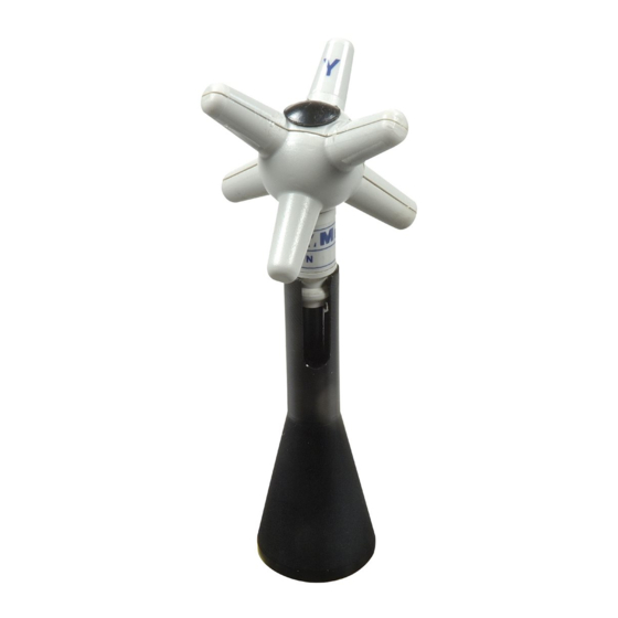
Page 36: Mounted On Conical Holder
- Pull the probe gently downwards until the probe plug is locked in the conical holder top. - The installation is now completed. Fig. 2-3 EP-600/601/602/603 Fig. 2-4 EP-604 mounted on mounted on conical holder conical holder As a general rule, when measuring the field from a transmitting antenna it is advisable to position the probe supporting devices perpendicular to the antenna polarization, particularly for frequencies in the range of megahertz. - Page 37 To remove the PMM EP-600/601/602/603/604 correctly from the conical 2.10.1.1 EP-600/601/602 holder: 603/604 removal - Hold the probe and conical holder in vertical position from the - Hold the probe as shown in the picture. Handle the probe with care. conical holder - With the conical holder in vertical position, gently rotate the probe of 45°...
- Page 38 It is recommended to make use of the optional tripod PMM TR-02 to 2.10.2 EP-600/601/ position the PMM EP-600/601/602/603/604 as required by the reference 602/603/604 standards. Maintaining the same hardware configuration contributes to installation improve the measurement repeatability (see chapter “Accessories”). on tripod Fix the EP-600/601/602/603/604 conical holder to the tripod TR-02A by PMM TR-02...
- Page 39 3 – Measurements The following procedures and measurement methods apply to 3.1 Foreword electromagnetic field sources present in industrial, medical, research, residential and telecommunication applications.. 3.2 Preliminary Before starting measuring electromagnetic fields (EMF) potentially dangerous, it’s advisable to determine the known characteristics of the sources and their possible propagation characteristics.
- Page 40 3.3 General requirements The basic components of a field measuring equipment are: - field probe (field sensor and transducer) - connecting cables - metering and data processing equipment 3.3.1 Probes As a general rule the field probes must respect the following conditions: •...
- Page 41 To prevent influencing the field measurements the operator, vehicles etc. 3.6 Preventing should stay away of 5 meters from the field sensor; the same should not be measurement errors located near metallic or conductive surfaces and objects. From the definition of difference of potential between two points: −...
- Page 42 The EP-600/601/602/603/604 field probe is allocated in a spherical plastic 3.7 PMM EP-600/601/ housing with 6 orthogonal monopoles that allow for immediate identification 602/603/604 operation of the electric field vectors (axis). The PMM EP-600/601/602/603/604 is supplied from an internal battery that can be recharged by the charge EP600 CHARGER supplied with.
- Page 43 The PMM EP-600/601/602/603/604 can be connected to the PC via fiber optic either when ON or OFF. When making measurements with PMM EP-600/601/602/603/604 the power supply must be ALWAYS removed. The min. battery voltage allowed for proper operation is of 2,05 V; it is displayed by the PC software WinEP600.
- Page 44 The PMM EP-600/601/602/603/604 field probe is connected to the user’s 3.8 Applications PC via fiber optic and the optic to serial converter (see chapter Operation). The wide frequency range and small size allow for using the PMM EP- 3.8.1 EMC 600/601/602/603/604 in EMC applications for monitoring the field strength during radiated immunity tests in open site, TEM/GTEM and anechoic chamber.
- Page 45 Fig. 3-3 PMM EP-600/601/602/603/604 in Anechoic Chamber Measurements...
- Page 46 The EP-600/601/602/603/604 can be connected and operated by the meter 3.9 Operating PMM 8053B. PMM EP-600/601/ 602/603/604 with 8053B (Option) Fig. 3-4 EP-600/601/602/603 with 8053B Fig. 3-5 EP-604 with 8053B - Display of field strength in ABS/%, MIN-MAX/AVG, MIN-MAX/RMS modes. - Graph of field strength in PLOT mode.
- Page 47 - Field strength data recording in Data Logger mode. For further information on configuration and operation with PMM 8053B, please refer to the operation manual supplied with it. The optional accessory PMM SB10 allows for controlling up to 10 field 3.10 Operating EP-600/ probes at the same time.
- Page 48 The PC software supplied with the PMM SB10 allows for simultaneous displaying of the field strength measured by each single field probe. 3-10 Measurements...
- Page 49 4 – Battery charger EP600 CHARGER The probe EP-600/601/602/603/604 internal circuitry is supplied by a 4.1 Foreword rechargeable Li-Mn internal battery to recharge by means of the battery charger EP600 CHARGER connected to the mains by means of the supplied adapter. The EP600 CHARGER is intended for this application only;...
-
Page 50: Ac Adapter
Fig. 4-3 EP600 CHARGER Always connect the AC adapter to the PMM EP600 CHARGER prior to plug 4.2 AC adapter to the mains by the supplied power cable. Output: DC, 10 - 15 V, ~ 500 mA Connector polarity: 4.3 EP600 CHARGER The following conditions apply to all specifications: •... -
Page 51: Ep600 Charger Components
4.3.2 EP600 CHARGER Description: components 1 – Knob and Spring 2 – Charging connector 3A – Charging status Led 3B – DC Supply connector Fig. 4-4 EP600 CHARGER components Attempting to charging batteries of different types or dry cells may cause explosion of the same and is strictly forbidden. -
Page 52: Ep-600/601/602/603 On Ep600 Charger
A first complete charging cycle is recommended to achieve the max 4.4 Installing EP-600/601 autonomy. /EP602/603/604 on To install the probe EP-600/601/602/603/604 on the battery charger EP600 EP600 CHARGER CHARGER: - place the EP600 CHARGER on a flat, stable surface - hold and lift up the knob as shown in figure - Insert the EP-600/601/602/603/604 on the EP600 CHARGER in correspondence of the threaded contact pin. - Page 53 - Plug the power cable to the AC adapter - Plug the power cable to the mains - Check the Led status as the table below: Fig. 4-6 EP-604 Fig. 4-5 EP-600/601/602/603 on the EP600 CHARGER on the EP600 CHARGER EP600 CHARGER...
- Page 54 Table 4-2 EP600 CHARGER Led status - Start up phase The EP600 CHARGER is supplied but without load (battery not Green present or disconnected or completely full) *. Orange Charge ended after 10 minutes of no load (led fix green) *** The charging circuit is overloaded (the output is OFF for 30 seconds before attempting a new charging cycle).
- Page 55 5 – WinEP600 and SetAddEP600 Operating instructions This section provides the information necessary to install and use the 5.1 Foreword WinEP600 software and SetAddEP600 utility with the PMM EP- 600/601/602/603/604 field probe. The SetAddEP600 is a utility that integrates the PMM SB10 Switching Control Box and the PMM EP-600/601/602/603/604.
- Page 56 To install the WinEP600 and the SetAddEP600 on PC from the supplied Software 5.3 Installation Media as follows: Do not connect the PMM EP-600/601/602/603/604 to the PC until the installation is completed. Browse the Software Media in Computer Resources and double click on the WinEP600.exe file to start the installation The User must have administrator privileges to install the WinEP600 and the SetAddEP600 in Windows 7, 8 etc.;...
- Page 57 In Windows Vista most programs are blocked for computer protection. To start the installation correctly it might be necessary to authorize the operation. The installation folder must be specified. Click Next to confirm the default folder or Change to modify. WinEP600 and SetAddEP600 operating instructions...
- Page 58 Click Next to proceed installing. The installing status is displayed then: WinEP600 and SetAddEP600 operating instructions...
- Page 59 Click Finish to complete and exit the installer. The folder WinEP600 and SetAddEP600 are created under Programs with the icon WinEP600 on desktop. Create the SetAddEP600 shortcut on your desktop. WinEP600 and SetAddEP600 operating instructions...
- Page 60 Running WinEP600 software Before to start WinEP600, it is recommended to limit the applications running on your computer. Connect the 8053-OC to the PC first serial port available or to the PC USB port by USB-RS232 adapter provided. Then connect the PMM EP- 600/601/602/603/604 to the converter (for more details see chapter “Operation”).
- Page 61 The user can quickly change the desired communication channel by clicking onto the Comm port drop-down menu. When the menu is selected, the communication port selector appears. It allows the user to choose between the RS232 port or RS232-to-USB converter that is needed if no RS232 port is available in the controller PC. When the USB connection is used, the USB-RS232 adapter appears among the devices as a “Prolific USB to Serial Comm Port (COMn)”.
- Page 62 This message appears when PMM EP-600/601/602/603/604 is not connected or the communication is not established: Select NO to quit the WinEP600. Select YES to retry establishing the communication (check the PMM EP- 600/601/602/603/604 correct installation before). Once connected the main window is displayed: 5.5 Main window contents Commands description:...
- Page 63 The software release shown here, together with the serial port as set in the 5.5.1 Title bar program properties. The control buttons allow to minimize to icon, enlarge/restore the main window and exit the program: When minimizing the main window the information is displayed in the Windows application bar at the bottom of screen.
- Page 64 The measurements displayed in the main window are: 5.5.2 Main window displayed - Electric field values as x - y - z or total (see par. “XYZ / TOT”) measurements Mode x - y - z Mode Total (TOT) - Measuring unit shows the electric field measuring unit; the value is displayed with three decimals.
- Page 65 This setting in MHz recalls the corresponding frequency correction factor 5.5.3 Frequency stored in the EP-600/601/602/603/604 memory. It allows an extremely correction setting precise measurement of the field level at the selected frequency. The graph in chapter 1 shows the correction factor in db as a function of the working frequency.
- Page 66 It shows the time interval (in seconds) between subsequent readings. 5.5.4 Reading Rate Setting resolution of 0.1 s. setting Press the enter key to enter the set frequency value. The setting displayed at the first run is the default; the last setting will be displayed then.
- Page 67 5.5.5 XYZ / TOT Button for selecting the x - y – z (XYZ) or Total mode (TOT). Max. display resolution: 0.001 V/m. Click on the XYZ button to toggle to Total mode. If the field value measured is outside the nominal level range, the following messages are displayed: Ovr : the field level is higher than 110% of the nominal maximum level (550 V/m for EP601).
- Page 68 5.5.6 Save Meas Active Measurements Log (√) to display the Save Meas button in the main window. When the software starts, the function Measurements Log is disabled Every time the button Save Meas is selected, the field value is stored in the file EP600_Measurements.txt file located on the installation folder;...
- Page 69 For every working session (from starting to closing the software) the following headline will be created in the txt file: dd/mm/yyyy: working session date. (EP600 model): between brackets is reported the EP600 model connected Time: hour, minute, second of the measurement acquisition X(unit) Y(unit) Z(unit): field value on x, y and z axis.
- Page 70 Use the button Settings at the bottom of the screen to customize the plot appearance: - The resolution time ( Time/Div (s) ); - Allow to change the probe level displayed on the graph from the maximum (100%) to 25% in 25% steps (Scale).
- Page 71 Once modified the appearance of the graph, press Play to start the analysis. In this case, the analysis is done with Time/Div set to 5s . At any time, the graph can be paused or terminated by clicking the STOP button Once pressed Pause button, it will be shown a round marker with a “pausing”...
- Page 72 In pause mode, the field produced in that interval can be saved in table form pressing Save button The folder must be specified, enter the file name assigned to the work session and press Save The file is saved in TXT format and once the table is opened, a huge amount of data are available 5-18 WinEP600 and SetAddEP600 operating instructions...
- Page 73 During the session work, the graph can be resumed with button, the existing TXT file paused and saved at any time ( can be overwrote or a new one can be saved with a different file name). When the test is over, the graph can be terminate with and the following message will appear: Press OK to save.
- Page 74 Press HOLD to freeze the readings. 5.5.8 HOLD / RUN Click on the button to toggle from HOLD to RUN The button XYZ/TOT is active even when in HOLD. If the program is exit when in HOLD mode, it will restart in RUN mode. 5.5.9 EXIT Press EXIT to end the program.
- Page 75 Commands: 5.5.10 Settings menu - Settings: set Average and Filter - Preference: select program skin and enable the function Minimized UI - ? (Info): software and product information 5.5.10.1 Settings Settings options: - Filter: the EP-600/601/602/603/604 internal A/D Sigma-Delta converters feature digital filters to improve resolution and sensitivity, as well to reducing interferences.
- Page 76 Normally a fast field measurement is required for faster response and better stability when the field probe controls as feedback for a preset field value the radiated power of a system composed by antenna and RF generator. However, as faster the measurements as higher the noise is, with consequent reduction of sensitivity.
- Page 77 - Average: setting of the number (1, 4, 16, 32 or 64) of readings to calculate the arithmetic average (AVG). When setting Average = 1, the readings are not averaged and the current measurements are displayed. In the example, the average value of the last 16 field readings will be displayed.
- Page 78 5.5.10.2 Preference Functions of the Settings menu: - Settings Display: Different color combinations of the background and text are listed under Colors: The choice is made by selecting the corresponding to be changed and then using the Color Palette window. The new settings can be saved with Save.
- Page 79 - Minimized: enable the function Minimized UI (Unit Interface) to keep the field readings displayed on desktop when minimizing the main window on the tray. This window can be moved anywhere on the desktop, keeping its final position even at the next minimizing of the main window. To close this window, restore the main window from the tray and deselect the “Minimized UI”...
- Page 80 Contents: 5.5.10.3 ? (Info) - Info: Probe model, current firmware and date, current WinOR03 release and date, serial number, battery voltage and latest probe calibration. Battery voltages below 2.11V (5% of charge) are displayed red. - About: Manufacturer information. 5.5.10.4 ? (About) 5-26 WinEP600 and SetAddEP600 operating instructions...
- Page 81 Running SetAddEP600 utility Connect the 8053-OC to the PC first serial port available or to the PC USB port USB-RS232 adapter. Then connect 600/601/602/603/604 to the optical converter (for more details see chapter “Operation”). In some PC models, the power delivered through the DB9 connector may be not enough to supply the optical/serial converter 8053-OC.
- Page 82 If the COM port nr. NOT comprised between 1 and 9, double click the line Ports (COM & LPT) and Prolific USB to Serial Comm Port (COMx). Enter in Port settings and Advanced. Otherwise, if you are using the PC serial port check on Porta di comunicazione (COMx).
- Page 83 Select the icon SetAddEP600 with the right mouse button and enter on Properties Shorcut. Add the command COMM=N preceded by a space (in capital letters) at the end of the Destination field where N indicates the Serial or USB port to be used;...
- Page 84 Double click on Set AddEP600 icon for running the utility. The User must have administrator privileges to install the WinEP600 and the SetAddEP600 in Windows 7, 8 etc.; right click on WinEP600.exe file and click on “Run as administrator” to temporarily run the program or application as an administrator until close it (Windows also allows to mark an application so that it always runs with administrator rights).
- Page 85 This message appears when PMM EP-600/601/602/603/604 is not connected or the communication is not established: Select YES to quit the SetAddEP600. Select NO to retry establishing the communication (check the EP- 600/601/602/603/604 correct installation before). Once connected the main window is displayed: 5.7 Main window 1.
- Page 86 When the communication is established, the probe data displays: probe 5.7.2 Probe data model, release and data firmware and serial number. 5.7.3 New Address When the communication is established, the window displays the current probe address. Enter new address and press to store it.
- Page 87 Uninstalling WinEP600 and SetAddEP600 Press EXIT to quit Win EP600 or SetAddEP600, disconnect the EP-600 from the PC and uninstall the software and utility. In Windows XP: click Start, All Programs, WinEP600, Uninstall WinEP600. In Windows Vista or 7 click Windows and in Windows 10: click Start .
- Page 88 Uninstalling the driver of RS232-USB adapter Apply this method if the driver uninstaller (normally supplied with the hardware) is not available. Go to Control Panel Uninstall a Program. Select “PL-2303 USB-to- Serial” with right mouse button and select Uninstall. Click Remove, then Next to begin the driver uninstall.
- Page 89 When the Uninstall Complete screen displays, click Finish to end the program. Wait a few seconds more until the “PL-2303 USB-to- Serial” program is removed from the Control Panel Uninstall program list. WinEP600 and SetAddEP600 operating instructions 5-35...
- Page 90 This page has been left blank intentionally 5-36 WinEP600 and SetAddEP600 operating instructions...
- Page 91 6 - Communication protocol This chapter provides the information required to control the PMM EP- 6.1 Disclaimer 600/601/602/603/604 via the fiber optic connected to a PC and by means of user’s own PC software applications. Narda STS S.r.l supports the correctness of the information only, and disclaim for any consequence the use of such information may cause to anybody.
- Page 92 The available commands are of three categories: • Query COMMANDs • Setting COMMANDs • Operative COMMANDs The commands have this format: #00Qcommand(parameters)* where: # = command string start 00 = string always present Q = ? for query commands S for setting commands Command = command string (parameters) = setting parameters value (where present) * = command string end...
- Page 93 Table 6-1 Query Commands Command Description This query command #00?v* sends back a string containing information about model, release and date of firmware. Example of reply to the command #00?v*: "vEP600:1.02 10/05;" This query command #00?p* sends back a string containing information about date of calibration.
- Page 94 Table 6-2 Setting Commands Command Description This setting command #00k frq* sets the frequency(frq) to which refer the correction factor. The figure fr is the ASCII string representing the integer frequency multiplied by 100 giving thus the resolution of 10kHz. Once the EP-600 has received and granted this command, all measurements will be corrected using the factor stored in factory related to this frequency.
- Page 95 Table 6-3 Operative Commands Command Description This setting command #00@c* temporarily puts the EP-600 in “Storing Mode” allowing thus storing a new address. As this permission lasts only for 1 second, the command “I” should be issued closely. This command has not a reply. Example of command #00@c* This setting command #00@Iaddr* sets the address used for communication protocol.
- Page 96 This page has been left blank intentionally Communication protocol...
- Page 97 7 – DLL Function reference guide All the following examples are indifferently referred to the PMM EP- 600, EP-601, EP-602, EP-603 and EP-604. The DLL library manages only the broadcast address (“00”). 7.1 C language 7.1.1 PMM_CreateProbe() int PMM_CreateProbe( const char *name, HANDLE *probeHandle, const char *commPort); Purpose: Establishes communications with a specified probe.
- Page 98 7.1.4 PMM_ProbeName() int PMM_ProbeName(const HANDLE probeHandle, char *name, int *arraySize); Purpose: Return the probe name identification information. Return Value: Returns an integer status code. The numeric value of 0 indicates no error occurred. See Status Code chapter for an error code description. Input Parameters: HANDLE probeHandle;...
- Page 99 7.1.7 PMM_ReadBattery() int PMM_ReadBattery(HANDLE probeHandle, float *battery); Purpose: This function reads the probe’s battery status. Return Value: Returns an integer status code. The numeric value of 0 indicates no error occurred. See Status Code chapter for an error code description. Input Parameters: HANDLE probeHandle Output Parameters:...
- Page 100 7.1.10 PMM_SetFrequency() int PMM_SetFrequency(const HANDLE probeHandle, int Frequency); Purpose: Sets the frequency to which refer the correction factor. Once the EP-600 has received and granted this command, all measurements will be corrected using the factor stored in factory related to this frequency. Return Value: Returns an integer status code.
- Page 101 7.1.13 PMM_SetAutoOffTime() int PMM_SetAutoOffTime(const HANDLE probeHandle, int Time); Purpose: Sets the time before the EP-600 auto-switches off after having received a recognized command. Return Value: Returns an integer status code. The numeric value of 0 indicates no error occurred. See Status Code chapter for an error code description. Input Parameters: HANDLE probeHandle, int time in seconds.
- Page 102 From the Project menu, select References to call up the References dialog 7.2 Visual Basic box, and then click Browse to find your new type library (PMM_EP60X.tlb). Once you have located it, press OK. Visual Basic will automatically register the library for you the first time you reference it. Make sure that your library ("PMM_EP60X”) has been checked in the references List, and then close the dialog box.
- Page 103 8 - Accessories This chapter explains how to use the accessories of PMM EP- 8.1 Foreword 600/601/602/603/604. The following general indications apply to all accessories. Check the packing integrity. 8.2 Inspection If anything is found damaged or missed, immediately contact your Dealer.
- Page 104 This page has been left blank intentionally Accessories...
- Page 105 PMM 8053-OC Optical-Serial converter This accessory of the field probe PMM EP-600/601/602/603/604 allows the fiber optic to be connected to the PC RS-232 serial port. Connect the PMM 8053-OC to a free serial port of PC; connect the fiber Installation optic of the probe respecting the optical connector insertion key.
- Page 106 This page has been left blank intentionally Accessories...
- Page 107 8053-OC-PS Power Supply This accessory of the field probe PMM EP-600/601/602/603/604 allows for providing the power supply to the 8053-OC converter whenever the PC serial port power supply is not sufficient or absent. Connect the 8053-OC-PS to the PC serial port (or serial cable) and to the Installation 8053-OC.
- Page 108 This page has been left blank intentionally Accessories...
- Page 109 PMM TR-02A Tripod This accessory allows for standing the PMM EP-600/601/602/603/604 field probe or the PMM 8053B hand held unit by means of the fixing screw. The swivel PMM 8053-SN is supplied together with the tripod. The PMM TR-02A has been specifically designed to prevent influencing the field measurements.
- Page 110 Details: The inclination of each leg can be set in three different positions: • Fixed 20°: white mark • Fixed 45°: red mark • Variable: no marks visible. The central support can be set and locked by the handle. Fig. 8-4 EP-604 on TR02A Fig.
- Page 111 The swivel PMM 8053-SN can be mounted on the PMM TR-02A top. • height: 8 cm • weight: 160 g • Load max: 10 kg • Screw: ¼ “ Fig. 8-5 EP-600/601/602/603 on adjustable swivel Fig. 8-6 EP-604 on adjustable swivel Accessories...
- Page 112 This page has been left blank intentionally 8-10 Accessories...
- Page 113 PMM TT-01 Telescopic extension PMM TT-01 allows for extending the distance between field probe and operator or measuring instrument. The TT-01 top is provided with the screw to fix the conical adapter. The length can be adjusted at any value between minimum and maximum. The PMM TT-01 is made of fibreglass and has been specifically designed to prevent influencing the field measurements.
- Page 114 This page has been left blank intentionally 8-12 Accessories...
- Page 115 PMM SB-10 Switching Control Box 8.10 Please refer to SB-10 User’s manual. Fig. 8-9 SB-10 front view Fig. 8-10 SB-10 rear view Accessories 8-13...
- Page 116 This page has been left blank intentionally 8-14 Accessories...
- Page 117 Sales & Support: Manufacturing Plant: NARDA Via Rimini, 22 Via Benessea, 29/B Safety 20142 - Milano (MI) 17035 Cisano sul Neva (SV) Test Tel.: +39 02 581881 Tel.: +39 0182 58641 Solutions Fax: +39 02 58188273 Fax: +39 0182 586400 S.r.l.
- Page 118 Suggerimenti / Commenti / Note: Suggestions / Comments / Note:...
Need help?
Do you have a question about the narda PMM EP-600 and is the answer not in the manual?
Questions and answers