Sign In
Upload
Download
Table of Contents
Contents
Add to my manuals
Delete from my manuals
Share
URL of this page:
HTML Link:
Bookmark this page
Add
Manual will be automatically added to "My Manuals"
Print this page
×
Bookmark added
×
Added to my manuals
Manuals
Brands
Beckhoff Manuals
Touch terminals
KL2532
Documentation
Beckhoff KL2532 Documentation
Two channel power stage terminals for dc motors
Hide thumbs
1
2
3
4
5
6
7
8
9
10
11
12
13
14
15
16
17
18
19
20
21
22
23
24
25
26
27
28
29
30
31
32
33
34
35
36
37
38
39
40
41
42
43
44
45
46
47
48
49
50
51
52
53
54
55
56
57
58
59
60
61
62
63
64
65
page
of
65
Go
/
65
Contents
Table of Contents
Bookmarks
Table of Contents
Table of Contents
1 Foreword
Notes on the Documentation
Safety Instructions
Documentation Issue Status
Beckhoff Identification Code (BIC)
Fig. 1 BIC as Data Matrix Code (DMC, Code Scheme ECC200)
2 Product Overview
KL2532 - Introduction
KL2552 - Introduction
Technical Data
KL2532 - LED Displays
Fig. 4 KL2532 - Leds
KL2552 - LED Displays
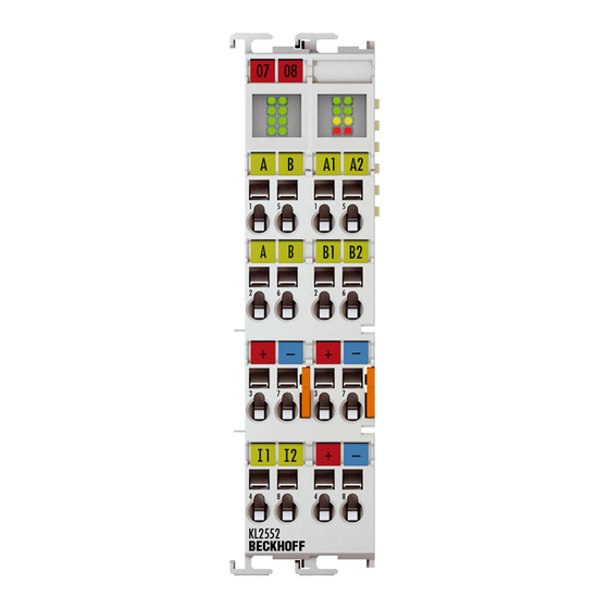
Fig. 5 KL2552 - Leds
3 Basic Function Principles
Basic Principles
Chopper Operation
Fig. 6 Current through the Brake Resistor
4 Mounting and Wiring
Instructions for ESD Protection
Installation on Mounting Rails
Fig. 7 Spring Contacts of the Beckhoff I/O Components
Fig. 8 Attaching on Mounting Rail
Fig. 9 Disassembling of Terminal
Installation Instructions for Enhanced Mechanical Load Capacity
Fig. 10 Power Contact on Left Side
Installation Position for Operation with or Without Fan
Fig. 11 Recommended Distances of Installation Position for Operating Without Fan
Fig. 12 Recommended Distances for Installation Position for Operation with Fan
Fig. 13: Other Installation Positions, Example 1
Connection
Connection System
Fig. 14: Other Installation Positions, Example 2
Fig. 15 Standard Wiring
Fig. 16 Pluggable Wiring
Fig. 17 High Density Terminals
Wiring
Fig. 18 Connecting a Cable on a Terminal Point
Shielding
UL Notice - Compact Motion
KL2532/KS2532 - Connection
Fig. 19 KL2532/KS2532 Pin Assignment
KL2552-0000/KS2552-0000 - Connection
Fig. 20 KL2552/KS2552 Pin Assignment
KL2552-0005/KS2552-0005 - Connection
Fig. 21 KL2552-0005/KS2552-0005 Pin Assignment
KL2552 - Application Example
Fig. 22 KL2552 Application Example
5 Configuration Software KS2000
KS2000 - Introduction
Fig. 23 KS2000 Configuration Software
Parameterization with KS2000
Fig. 24 Display of the Fieldbus Station in KS2000
Fig. 25 KS2000 Tree Branches for Channel 1 of the KL2552
Register
Fig. 26 Register View in KS2000
Settings
Fig. 27 Settings Via KS2000
Process Data
Fig. 28 Procdata
Fig. 29 History Field
Fig. 30 Value Field
Fig. 31 Value Field
Fig. 32 Settings
6 Access from the User Program
Process Image
Control and Status Bytes
Register Overview
Register Description
Fig. 2 KL2532
Fig. 3 KL2552
Examples of Register Communication
Example 1: Reading the Firmware Version from Register 9
Example 2: Writing to an User Register
7 Appendix
List of Illustrations
Advertisement
Quick Links
Download this manual
Documentation
KL2532/KS2532, KL2552/KS2552
Two channel power stage terminals for DC motors
Version:
Date:
3.2.0
2019-09-23
Table of
Contents
Previous
Page
Next
Page
1
2
3
4
5
Advertisement
Chapters
Table of Contents
3
List of Illustrations
65
Table of Contents
Need help?
Do you have a question about the KL2532 and is the answer not in the manual?
Ask a question
Questions and answers
Related Manuals for Beckhoff KL2532
Touch terminals Beckhoff KL2542 Documentation
Two channel output stage terminal for dc motors (42 pages)
Touch terminals Beckhoff KS2542 Manual
Two channel output stage terminals for dc motors (46 pages)
Touch terminals Beckhoff KL2535 Documentation
Pulse width current terminals (49 pages)
Touch terminals Beckhoff KS2535, KL2545 Manual
Pulse width current terminals (54 pages)
Touch terminals Beckhoff KL2545 Documentation
Pulse width current terminals (49 pages)
Touch terminals Beckhoff KL2521 Series Documentation
One channel pulse train output terminals, rs422 / 24 v dc (43 pages)
Touch terminals Beckhoff KL2552 Documentation
Two channel power stage terminals for dc motors (65 pages)
Touch terminals Beckhoff KL2761 Documentation
Single channel universal dimmer terminals (54 pages)
Touch terminals Beckhoff KL2602 Series Documentation
Two-and four-channel relay output terminals (33 pages)
Touch terminals Beckhoff KL2622 Series Documentation
Two-and four-channel relay output terminals (33 pages)
Touch terminals Beckhoff KL26 Series. KS26 Series Documentation
Relais output terminals (47 pages)
Touch terminals Beckhoff KL28 Series Manual
Hd bus terminals with digital outputs, 24 v dc (39 pages)
Touch terminals Beckhoff KL2809 Documentation
Hd bus terminals, digital output 24 v dc (34 pages)
Touch terminals Beckhoff KL2798 Documentation
Bus terminal, 8-channel solid state output, 30 v ac, 48 v dc,2 a, potential-free (22 pages)
Touch terminals Beckhoff KL2612 Documentation
Relais output terminals (47 pages)
Touch terminals Beckhoff KL2641 Documentation
Relais output terminals (47 pages)
This manual is also suitable for:
Ks2532
Kl2552
Ks2552
Table of Contents
Print
Rename the bookmark
Delete bookmark?
Delete from my manuals?
Login
Sign In
OR
Sign in with Facebook
Sign in with Google
Upload manual
Upload from disk
Upload from URL


Need help?
Do you have a question about the KL2532 and is the answer not in the manual?
Questions and answers