
Subscribe to Our Youtube Channel
Related Manuals for Beckhoff KL28 Series


Summary of Contents for Beckhoff KL28 Series
- Page 1 Documentation | EN KL28xx HD Bus Terminals with digital outputs, 24 V DC 2021-06-11 | Version: 1.1.0...
-
Page 3: Table Of Contents
Table of contents Table of contents 1 Foreword .............................. 5 Notes on the documentation...................... 5 Safety instructions .......................... 6 Documentation Issue Status...................... 7 Interference-free Bus Terminals ...................... 8 2 Product overview............................. 12 KL2808 ............................ 12 2.1.1 Introduction and contact assignment ................ 12 2.1.2 Technical data ......................... 14 KL2828 ............................ 15 2.2.1 Introduction and contact assignment ................ - Page 4 Table of contents Version: 1.1.0 KL28xx...
-
Page 5: Foreword
, XTS and XPlanar are registered trademarks of and licensed by Beckhoff Automation GmbH. Other designations used in this publication may be trademarks whose use by third parties for their own purposes could violate the rights of the owners. Patent Pending... -
Page 6: Safety Instructions
All the components are supplied in particular hardware and software configurations appropriate for the application. Modifications to hardware or software configurations other than those described in the documentation are not permitted, and nullify the liability of Beckhoff Automation GmbH & Co. KG. Personnel qualification This description is only intended for trained specialists in control, automation and drive engineering who are familiar with the applicable national standards. -
Page 7: Documentation Issue Status
Foreword Documentation Issue Status Version Comment 1.1.0 • Technical data updated • Chapter Instructions for ESD protection added • Design of the safety instructions adapted to IEC 82079-1 • New title page 1.0.0 • First release Hardware versions The hardware versions (delivery state) can be taken from the serial number printed on the side of the terminal. -
Page 8: Interference-Free Bus Terminals
Foreword Interference-free Bus Terminals Use of interference-free Bus or EtherCAT Terminals in safety applications If a Bus or EtherCAT Terminal is described as interference-free, this means that the consecutive terminal behaves passively in a safety application (e.g. in the case of the all-pole switch-off of a po- tential group). -
Page 9: Fig. 1 Negative Example - Active Load
Foreword External wiring The following requirements are to be ensured by the system manufacturer and must be incorporated into the user documentation. • Protection class IP54 The terminals must be installed in IP54 control cabinets to ensure the necessary protection class IP54. •... -
Page 10: Fig. 2 Ground Connection Of The Load: Correct (K1) And Incorrect (K2)
Foreword Fig. 2: Ground connection of the load: correct (K1) and incorrect (K2) ◦ If either a) the ground of the load is not fed back to the terminal or b) the ground is not safely switched but connected permanently then fault exclusions are necessary with regard to a short-circuit with external potential in order to be able to achieve Cat. -
Page 11: Fig. 3 Short Circuit Fault Exclusion Through Protected Cable Laying
Foreword Fig. 3: Short circuit fault exclusion through protected cable laying ◦ a) Possibility 1: Load connection via separate sheathed cables The non-safely switched potential of the standard terminal may not be conducted together with other potential-conducting cores inside the same sheathed cable. (Fault exclusion, see EN ISO 13849-2:2013, Table D.4) ◦... -
Page 12: Product Overview
Product overview Product overview Terminal Outputs Voltage Current Comment 24 V 0,5 A KL2808 [} 12] 24 V 2 A KL2828 [} 15] 24 V 0,5 A KL2809 [} 18] KL2872-0000 [} 21] 16 24 V 0,5 A ribbon cable connection KL2872-0010 [} 21] 16 24 V 0,5 A ribbon cable connection, ground switching 24 V 0,5 A ground switching KL2889 [} 18]... - Page 13 Product overview KL2808 - LEDs Color Meaning OUTPUT 1- 8 green No output signal 24 V output signal at the respective output KL2808 – contact assignment Terminal point Description Name Output 1 Output 1 Output 2 Output 2 Output 3 Output 3 Output 4 Output 4...
- Page 14 Product overview 2.1.2 Technical data Technical data KL2808 Connection technology 2-wire Number of Outputs Rated load voltage 24 V (-15% / +20%) Load type ohmic, inductive, lamp load Output current max. 0.5 A (short-circuit-proof) per channel Short circuit current < 2 A Breaking energy <...
-
Page 15: Introduction And Contact Assignment
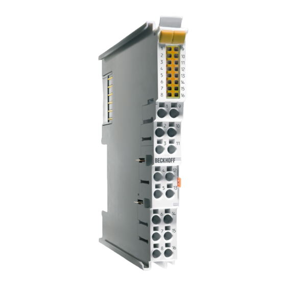
Product overview KL2828 2.2.1 Introduction and contact assignment Fig. 5: KL2828 HD Bus Terminal, 8-channel digital output 24 V , 2 A The 8-channel KL2828 digital output terminal connects the binary control signals from the electrically isolated automation device on to the actuators at the process level. The KL2828 is protected against polarity reversal and processes load currents with outputs protected against overload and short-circuit. - Page 16 Product overview KL2828 - contact assignment Terminal point Description Name Output 1 Output 1 Output 2 Output 2 Output 3 Output 3 Output 4 Output 4 Output 5 Output 5 Output 6 Output 6 Output 7 Output 7 Output 8 Output 8 0 V 0 V (internally connected to terminal point 10, 11, 12, 13, 14, 15, 16 and...
-
Page 17: Technical Data
Product overview 2.2.2 Technical data Technical data KL2828 Connection technology 2 wire Number of outputs Rated load voltage 24 V (-15% / +20%) Load type ohmic, inductive, capacitive Output current max. 2 A per channel (∑ max. 10 A) Short circuit current < 40 A typ. Breaking energy <... -
Page 18: Introduction And Contact Assignment
Product overview KL2809, KL2889 2.3.1 Introduction and contact assignment Fig. 6: KL2809 Fig. 7: KL2889 Version: 1.1.0 KL28xx... - Page 19 Product overview HD Bus Terminals, 16-channel digital output 24 V , 0.5 A The KL2809 digital output terminal connects the binary control signals from the automation device on to the actuators at the process level with electrical isolation. The KL2809 is protected against polarity reversal and processes load currents with outputs protected against overload and short-circuit.
-
Page 20: Technical Data
Product overview 2.3.2 Technical data Technical data KL2809 KL2889 Connection technology 1-wire Number of Outputs Rated load voltage 24 V (-15% / +20%) Load type ohmic, inductive, lamp load Output current max. 0.5 A (short-circuit-proof) per channel Short circuit current < 2 A < 7 A Breaking energy <... -
Page 21: Kl2872-0000, Kl2872-0010
Product overview KL2872-0000, KL2872-0010 2.4.1 Introduction and contact assignment Fig. 8: KL2872 Fig. 9: KL2872-0010 KL28xx Version: 1.1.0... -
Page 22: Fig. 10 Dimensions Of The 20-Pin Contact Strip In The Terminal And The Matching Spring Contact Strip
Product overview Bus Terminals, 16-channel digital output 24 V , 0.5 A, flat-ribbon cable connection The KL2872-00x0 digital output terminals offers a very compact design with its 16 channels. It is thus ideally suited for multi-pin connector valve terminals. A 20-pin connector enables the secure connection of plug connectors using insulation displacement contact, as is usual for ribbon cables and special round cables. -
Page 23: Technical Data
Product overview 2.4.2 Technical data Technical data KL2872-0000 KL2872-0010 Connection technology flat-ribbon cable Number of Outputs Rated load voltage 24 V (-15 %/+20 %) Load type ohmic, inductive, lamp load Output current Max 0.5 A (short-circuit-proof) per channel Short circuit current <... -
Page 24: Mounting And Wiring
• Surroundings (working place, packaging and personnel) should by grounded probably, when handling with the devices. • Each assembly must be terminated at the right hand end with a KL9010 bus end terminal, to ensure the protection class and ESD protection. Fig. 11: Spring contacts of the Beckhoff I/O components Version: 1.1.0 KL28xx... -
Page 25: Installation On Mounting Rails
Mounting and wiring Installation on mounting rails WARNING Risk of electric shock and damage of device! Bring the bus terminal system into a safe, powered down state before starting installation, disassembly or wiring of the bus terminals! Assembly Fig. 12: Attaching on mounting rail The bus coupler and bus terminals are attached to commercially available 35 mm mounting rails (DIN rails according to EN 60715) by applying slight pressure: 1. -
Page 26: Fig. 13 Disassembling Of Terminal
Mounting and wiring Disassembly Fig. 13: Disassembling of terminal Each terminal is secured by a lock on the mounting rail, which must be released for disassembly: 1. Pull the terminal by its orange-colored lugs approximately 1 cm away from the mounting rail. In doing so for this terminal the mounting rail lock is released automatically and you can pull the terminal out of the bus terminal block easily without excessive force. -
Page 27: Installation Instructions For Enhanced Mechanical Load Capacity
Mounting and wiring Fig. 14: Power contact on left side NOTE Possible damage of the device Note that, for reasons of electromagnetic compatibility, the PE contacts are capacitatively coupled to the mounting rail. This may lead to incorrect results during insulation testing or to damage on the terminal (e.g. disruptive discharge to the PE line during insulation testing of a consumer with a nominal voltage of 230 V). -
Page 28: Connection System
Mounting and wiring Additional installation instructions For terminals with enhanced mechanical load capacity, the following additional installation instructions apply: • The enhanced mechanical load capacity is valid for all permissible installation positions • Use a mounting rail according to EN 60715 TH35-15 •... -
Page 29: Fig. 16 Pluggable Wiring
Mounting and wiring Pluggable wiring Fig. 16: Pluggable wiring The terminals of KSxxxx and ESxxxx series feature a pluggable connection level. The assembly and wiring procedure for the KS series is the same as for the KLxxxx and ELxxxx series. The KS/ES series terminals enable the complete wiring to be removed as a plug connector from the top of the housing for servicing. -
Page 30: Fig. 18 Mounting A Cable On A Terminal Connection
Mounting and wiring Wiring Terminals for standard wiring ELxxxx/KLxxxx and for pluggable wiring ESxxxx/KSxxxx Fig. 18: Mounting a cable on a terminal connection Up to eight connections enable the connection of solid or finely stranded cables to the Bus Terminals. The terminals are implemented in spring force technology. -
Page 31: Installation Positions
Mounting and wiring Shielding Shielding Analog sensors and actors should always be connected with shielded, twisted paired wires. Installation positions NOTE Constraints regarding installation position and operating temperature range Please refer to the technical data for a terminal to ascertain whether any restrictions regarding the installa- tion position and/or the operating temperature range have been specified. -
Page 32: Fig. 20 Other Installation Positions
Mounting and wiring Other installation positions All other installation positions are characterized by different spatial arrangement of the mounting rail - see Fig Other installation positions. The minimum distances to ambient specified above also apply to these installation positions. Fig. 20: Other installation positions Version: 1.1.0 KL28xx... -
Page 33: Atex - Special Conditions (Standard Temperature Range)
80°C at the wire branching points, then cables must be selected whose tempera- ture data correspond to the actual measured temperature values! • Observe the permissible ambient temperature range of 0 to 55°C for the use of Beckhoff fieldbus compo- nents standard temperature range in potentially explosive areas! •... -
Page 34: Atex - Special Conditions (Extended Temperature Range)
80°C at the wire branching points, then cables must be selected whose tempera- ture data correspond to the actual measured temperature values! • Observe the permissible ambient temperature range of -25 to 60°C for the use of Beckhoff fieldbus com- ponents with extended temperature range (ET) in potentially explosive areas! •... -
Page 35: Continuative Documentation For Atex And Iecex
IECEx Pay also attention to the continuative documentation Ex. Protection for Terminal Systems Notes on the use of the Beckhoff terminal systems in hazardous areas according to ATEX and IECEx that is available for download on the Beckhoff homepage www.beckhoff.com! KL28xx Version: 1.1.0... -
Page 36: Appendix
Please contact your Beckhoff branch office or representative for local support and service on Beckhoff products! The addresses of Beckhoff's branch offices and representatives round the world can be found on her internet pages: https://www.beckhoff.com You will also find further documentation for Beckhoff components there. - Page 37 KL2872-0010 ..........................Fig. 10 Dimensions of the 20-pin contact strip in the terminal and the matching spring contact strip ..Fig. 11 Spring contacts of the Beckhoff I/O components................. Fig. 12 Attaching on mounting rail ......................Fig. 13 Disassembling of terminal......................
- Page 39 More Information: www.beckhoff.com/KL2xxx Beckhoff Automation GmbH & Co. KG Hülshorstweg 20 33415 Verl Germany Phone: +49 5246 9630 info@beckhoff.com www.beckhoff.com...
Need help?
Do you have a question about the KL28 Series and is the answer not in the manual?
Questions and answers