All the components are supplied in particular hardware and software configurations appropriate for the application. Modifications to hardware or software configurations other than those described in the documentation are not permitted, and nullify the liability of Beckhoff Automation GmbH & Co. KG. Personnel qualification This description is only intended for trained specialists in control, automation and drive engineering who are familiar with the applicable national standards.
00 - hardware version 00 Beckhoff Identification Code (BIC) The Beckhoff Identification Code (BIC) is increasingly being applied to Beckhoff products to uniquely identify the product. The BIC is represented as a Data Matrix Code (DMC, code scheme ECC200), the content is based on the ANSI standard MH10.8.2-2016.
The following information is contained: Item Type of Explanation Data Number of digits Example information identifier incl. data identifier Beckhoff order Beckhoff order number 1P 1P072222 number Beckhoff Traceability Unique serial number, SBTNk4p562d7 Number (BTN) see note below Article description Beckhoff article 1KEL1809 description, e.g.
Page 9
Example of composite information from item 1 to 4 and 6. The data identifiers are marked in red for better display: An important component of the BIC is the Beckhoff Traceability Number (BTN, item no. 2). The BTN is a unique serial number consisting of eight characters that will replace all other serial number systems at Beckhoff in the long term (e.g.
Product overview KL2602-00x0, KL2622-00x0 - Introduction Fig. 2: KL2602, KL2602-0010 Fig. 3: KL2622, KL2622-0010 The KL2602/ KL2602-0010 (2 x normally open, with power contacts) and KL2622/ KL2622-0010 (2 x normally open) output terminals have two relays each of which has a single contact. The relay contact of the KL2602/ KL2602-0010 is connected to the power contacts and can be generally used for switching devices requiring mains power.
Page 12
Product overview Watchdogtimer-Overflow If no process data is transferred to the terminal from the Bus Coupler for 100 ms, the green signal-LEDs go out, and the relay contacts are opened after typical reaction time (see Technical data [} 13]). Process data The bit-width in the process image is 2 bits. Version: 2.4.0 KL2602, KL2622, KL2634...
Product overview KL2602-00x0, KL2622-00x0 - Technical data KL2602-0000 and KL2622-0000 Technical data KL2602-0000 KL2622-0000 Number of outputs 2 N/O contacts for power 2 N/O contacts (potential free) contact Contact material AgCdO Switching voltage max. 250 V / 30 V Switching current Max. 5 A Switching capacity max.
Page 14
Product overview KL2602-0010 and KL2622-0010 Technical data KL2602-0010 KL2622-0010 Number of outputs 2 x make contacts for power 2 x make contacts contact Contact material Ag-Alloy (Au plating applied to stationary contact) Rated load voltage 230 V / 30 V Load type ohmic, inductive, capacitive Switching current max.
Product overview KL2634-0000 - Introduction Fig. 4: KL2634 The terminal and KL2634 (4 x normally open) output terminal has four relays each of which has a single contact. The Bus Terminals indicate their signal state by means of light emitting diodes. The KL2634 bus terminal has potential-free contacts.
Product overview KL2634-0000 - Technical data Technical data KL2634-0000 Number of outputs 4 N/O contacts (potential-free) Contact material Ag-Alloy (Au plating applied to stationary contact) Switching voltage max. 250 V / 30 V Load type Ohmic, inductive Ohmic switching current Typ. 4 A AC/DC per channel Inductive switching current Typ.
• Each assembly must be terminated at the right hand end with a KL9010 bus end terminal, to ensure the protection class and ESD protection. Fig. 5: Spring contacts of the Beckhoff I/O components Installation on mounting rails WARNING...
Mounting and wiring Assembly Fig. 6: Attaching on mounting rail The bus coupler and bus terminals are attached to commercially available 35 mm mounting rails (DIN rails according to EN 60715) by applying slight pressure: 1. First attach the fieldbus coupler to the mounting rail. 2.
Mounting and wiring Disassembly Fig. 7: Disassembling of terminal Each terminal is secured by a lock on the mounting rail, which must be released for disassembly: 1. Pull the terminal by its orange-colored lugs approximately 1 cm away from the mounting rail. In doing so for this terminal the mounting rail lock is released automatically and you can pull the terminal out of the bus terminal block easily without excessive force.
Mounting and wiring Fig. 8: Power contact on left side NOTE Possible damage of the device Note that, for reasons of electromagnetic compatibility, the PE contacts are capacitatively coupled to the mounting rail. This may lead to incorrect results during insulation testing or to damage on the terminal (e.g. disruptive discharge to the PE line during insulation testing of a consumer with a nominal voltage of 230 V).
Mounting and wiring Standard wiring (ELxxxx / KLxxxx) Fig. 9: Standard wiring The terminals of ELxxxx and KLxxxx series have been tried and tested for years. They feature integrated screwless spring force technology for fast and simple assembly. Pluggable wiring (ESxxxx / KSxxxx) Fig. 10: Pluggable wiring The terminals of ESxxxx and KSxxxx series feature a pluggable connection level.
Mounting and wiring Wiring HD Terminals The High Density (HD) Terminals of the ELx8xx and KLx8xx series doesn't support pluggable wiring. Ultrasonically "bonded" (ultrasonically welded) conductors Ultrasonically “bonded" conductors It is also possible to connect the Standard and High Density Terminals with ultrasonically "bonded"...
Mounting and wiring KL2602-00x0 - Connector pin assignment and LEDs CAUTION Risk of injury! Bring the bus system into a safe, powered down state before starting installation, disassembly or wiring of the Bus Terminals! NOTE Possible damage of devices! When designing a Bus Terminal block with different potentials on the power contacts (e.g. 230 V 24 V ), please note that it is mandatory to use potential separation terminals (e.g.: KL9080)! Fig. 13: KL2602-0000 and KL2602-0010...
Mounting and wiring KL2622-00x0 - Connector pin assignment and LEDs CAUTION Risk of injury! Bring the bus system into a safe, powered down state before starting installation, disassembly or wiring of the Bus Terminals! NOTE Possible damage of devices! When designing a Bus Terminal block with different potentials on the power contacts (e.g. 230 V 24 V ), please note that it is mandatory to use potential separation terminals (e.g.: KL9080)! Fig. 14: KL2622-0000 and KL2622-0010...
Mounting and wiring KL2634-0000 - Connector pin assignment and LEDs CAUTION Risk of injury! Bring the bus system into a safe, powered down state before starting installation, disassembly or wiring of the Bus Terminals! NOTE Possible damage of devices! When designing a Bus Terminal block with different potentials on the power contacts (e.g. 230 V 24 V ), please note that it is mandatory to use potential separation terminals (e.g.: KL9080)! Fig. 15: KL2634-0000...
80°C at the wire branching points, then cables must be selected whose tempera- ture data correspond to the actual measured temperature values! • Observe the permissible ambient temperature range of -25 to 60°C for the use of Beckhoff fieldbus com- ponents with extended temperature range (ET) in potentially explosive areas! •...
Notes about operation of the Beckhoff terminal systems in potentially explosive ar- eas (ATEX) Pay also attention to the continuative documentation Notes about operation of the Beckhoff terminal systems in potentially explosive areas (ATEX) that is available in the download area of the Beckhoff homepage http:\\www.beckhoff.com! Version: 2.4.0...
Commissioning Commissioning Remarks for usage of relay terminals Analyze operation conditions It is extremely important to observe the technical specifications if fault-free operation is to be guar- anteed. If relays are to be used in a control system the expected operating conditions must be analyzed with great care.
Commissioning For the -0010 variants applies: The relays internally of these terminals would be switched near to the zero voltage crossing of an AC supply. Hereby the lifetime of the outputs is no longer dependent by the absolute lifetime of the relay. The result of an exemplary long term test with the following boundary conditions represent that: •...
Page 31
Commissioning Mains quality requirements If mains voltage as “detection” voltage is used: In the event of mains voltage faults, which jeopar- dize precise synchronization with the mains voltage zero crossing, suitable mains filters should be used. Temperature compensation of the terminal The terminal provides an automatic temperature compensation that allows a soft switching in a wide temperature range.
Beckhoff's branch offices and representatives Please contact your Beckhoff branch office or representative for local support and service on Beckhoff products! The addresses of Beckhoff's branch offices and representatives round the world can be found on her internet pages: http://www.beckhoff.com You will also find further documentation for Beckhoff components there.
Page 33
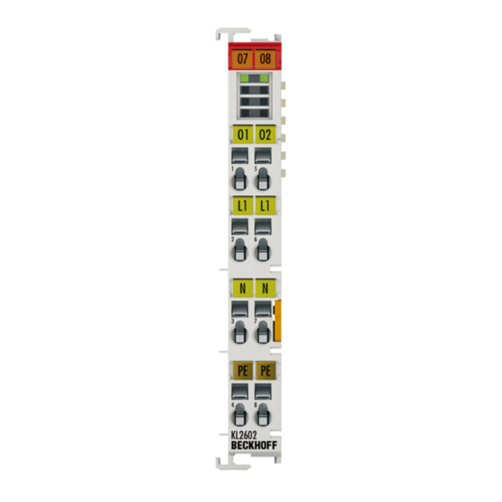
Fig. 2 KL2602, KL2602-0010......................... Fig. 3 KL2622, KL2622-0010......................... Fig. 4 KL2634 ............................Fig. 5 Spring contacts of the Beckhoff I/O components................. Fig. 6 Attaching on mounting rail ......................Fig. 7 Disassembling of terminal......................Fig. 8 Power contact on left side......................