Beckhoff KL2535 Documentation

Beckhoff KL2535 Documentation

Pulse width current terminals
Hide thumbs Also See for KL2535:
Table of Contents

Advertisement

Quick Links

Documentation
KL2535, KL2545
Pulse width current terminals
Version:
Date:
2.0.0
2016-02-29

Advertisement

Table of Contents
loading

Summary of Contents for Beckhoff KL2535

  • Page 1 Documentation KL2535, KL2545 Pulse width current terminals Version: 2.0.0 Date: 2016-02-29...
  • Page 3: Table Of Contents

    Safety instructions .......................... 5 Documentation issue status...................... 6 2 Product overview............................ 7 KL2535 - Introduction ........................ 7 KL2535 - Technical Data ........................ 8 KL2535 - LED displays ........................ 9 KL2545 - Introduction ........................ 10 KL2545 - Technical Data ........................  11 KL2545 - LED displays ........................ 12 Pulse width modulation........................
  • Page 4: Foreword

    XTS are registered trademarks of and licensed by Beckhoff Automation GmbH & Co. KG. Other designations used in this publication may be trademarks whose use by third parties for their own purposes could violate the rights of the owners.
  • Page 5: Safety Instructions

    All the components are supplied in particular hardware and software configurations appropriate for the application. Modifications to hardware or software configurations other than those described in the documentation are not permitted, and nullify the liability of Beckhoff Automation GmbH & Co. KG. Personnel qualification This description is only intended for trained specialists in control, automation and drive engineering who are familiar with the applicable national standards.
  • Page 6: Documentation Issue Status
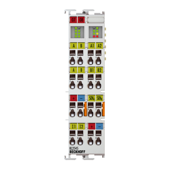
    1.2.0 • Mounting instructions extended • Technical data updated • Register overview updated 1.1.0 • Connection description for the KL2535 corrected • Basic function principles corrected • Hardware version of the KL2535 corrected First publication Internal proof copy Firmware and hardware versions...
  • Page 7: Product Overview

    The output stage is protected against overload and short-circuit and is electrically isolated from the K-bus. Both channels indicate their state by LEDs, enabling fast on-the-spot diagnosis. The Bus Terminal is available in the KL2535 version for standard wiring [} 22] and the KS2535 for permanent wiring [} 21].
  • Page 8: Kl2535 - Technical Data

    Product overview KL2535 - Technical Data Technical data KL2535/KS2535 Number of output stages Load type ohmic/inductive > 1 mH Supply for the output stage 24 V via power contacts Output current per channel 1 A (short-circuit-proof, common thermal overload warning for both output stages)
  • Page 9: Kl2535 - Led Displays

    Product overview KL2535 - LED displays LED indicators Fig. 2: KL2535 - LEDs Display Run (green) reserved Data transmission on the K-bus is active Enable A (green) off Channel 1 is either not enabled or not ready to operate. Channel 1 is enabled and is ready to operate.
  • Page 10: Kl2545 - Introduction

    The Bus Terminal is available in the KL2545 version for standard wiring [} 22] and the KS2545 for permanent wiring [} 21]. Version: 2.0.0 KL2535, KL2545...
  • Page 11: Kl2545 - Technical Data

    35 mm mounting rail conforms to EN 60715 Mounting [} 18] Vibration/shock resistance conforms to EN 60068-2-6 / EN 60068-2-27 EMC immunity/emission conforms to EN 61000-6-2 / EN 61000-6-4 Protection class IP20 Correct installation position see section Installation position [} 20] Approval KL2535, KL2545 Version: 2.0.0...
  • Page 12: Kl2545 - Led Displays

    Channel 2 is enabled and is ready to operate. Warning (yellow) The internal temperature has risen to more than 80°C, or the power supply voltage has dropped. Error B (red) There is an error at channel 2 Version: 2.0.0 KL2535, KL2545...
  • Page 13: Pulse Width Modulation

    Product overview Pulse width modulation The KL2535 and KL2545 pulse-width current terminals include an integrated PWM output stage (up to 175 W) in a very compact design. By means of the PWM output stage the pulse width modulation (PWM) of the supply voltage is used to regulate the output current of a connected ohmic/inductive load.
  • Page 14: Functions

    Product overview Functions The KL2535 and KL2545 pulse-width current terminals include an integrated PWM output stage (up to 175 W) in a very compact design. General functions Enable/Readiness for operation The enable bit CB1.5 [} 38] in the control byte must be set in order to activate the output stage. If the terminal is not subject to an error at this time, it acknowledges the command by setting the ready bit, SB1.4...
  • Page 15: Fig. 7 Frequency - F / Amplitude - I

    When switched on, the dither signal jumps immediately to the 32767 ms amplitude set in R38. When switched off, the signal is [} 44] attenuated linearly over the time configured here; the resolution is 1 ms. Fig. 7: Frequency - f / Amplitude - i KL2535, KL2545 Version: 2.0.0...
  • Page 16: Fig. 8 Switch-Off Ramp - T

    The area compensation region ends at this value - x process data value; the resolution is 0.1% (as [} 44] a fraction of 32767) The characteristic curve is divided into four regions: Overlapping Bend compensation III, III' Area compensation End region Version: 2.0.0 KL2535, KL2545...
  • Page 17: Fig. 9 Valve Curve

    32767 (resolution: 1 ms). [} 44] Falling ramp - t 0 to 32767 ms The time, t , required for the process data value to fall from 32767 to 0 (resolution: 1ms). [} 45] Fig. 10: Process data ramps KL2535, KL2545 Version: 2.0.0...
  • Page 18: Mounting And Wiring

    To mount the mounting rails with a height of 7.5 mm under the terminals and couplers, you should use flat mounting connections (e.g. countersunk screws or blind rivets). Version: 2.0.0 KL2535, KL2545...
  • Page 19: Fig. 12 Disassembling Of Terminal

    PE power contact The power contact labeled PE can be used as a protective earth. For safety reasons this contact mates first when plugging together, and can ground short-circuit currents of up to 125 A. KL2535, KL2545 Version: 2.0.0...
  • Page 20: Prescribed Installation Position

    EL/KL terminals to face forward (see Fig. Recommended distances for standard installation position). The terminals are ventilated from below, which enables optimum cooling of the electronics through convection. "From below" is relative to the acceleration of gravity. Version: 2.0.0 KL2535, KL2545...
  • Page 21: Connection System

    • The terminals of KSxxxx and ESxxxx series feature a pluggable connection level and enable steady wiring while replacing. • The High Density Terminals (HD Terminals) include electronics and connection level in a single enclosure and have advanced packaging density. KL2535, KL2545 Version: 2.0.0...
  • Page 22: Fig. 15 Standard Wiring

    12 mm Bus Terminals. Massive conductors and conductors with a wire end sleeve can be inserted directly into the spring loaded terminal point without tools. Version: 2.0.0 KL2535, KL2545...
  • Page 23: Fig. 18 Mounting A Cable On A Terminal Connection

    3. The terminal closes automatically when the pressure is released, holding the wire securely and permanently. Terminal housing ELxxxx, KLxxxx ESxxxx, KSxxxx Wire size width 0.08 ... 2,5 mm 0.08 ... 2.5 mm Wire stripping length 8 ... 9 mm 9 ... 10 mm KL2535, KL2545 Version: 2.0.0...
  • Page 24 0.25 ... 1.5 mm Wire size width (ultrasonically “bonded" conductors) only 1.5 mm (see notice [} 23]!) Wire stripping length 8 ... 9 mm Shielding Shielding Analog sensors and actors should always be connected with shielded, twisted paired wires. Note Version: 2.0.0 KL2535, KL2545...
  • Page 25: Kl2535 - Connection

    Mounting and wiring KL2535 - Connection Risk of injury through electric shock and damage to the device! Bring the Bus Terminals system into a safe, de-energized state before starting mounting, disassembly or wiring of the Bus Terminals. WARNING Fig. 19: KL2535 Connection...
  • Page 26: Kl2545 - Connection

    Digital input 2 (24 V The current counter value is saved as a reference mark in the latch register if bit CW.2 is set in the control word and a rising edge occurs at digital input 2. Version: 2.0.0 KL2535, KL2545...
  • Page 27 If the K-bus voltage fails (5 V, supplied from the supply voltage Us of the Bus Coupler), the output drivers are not reset! This means that the valves are then not driven back to the ini- WARNING tial position! KL2535, KL2545 Version: 2.0.0...
  • Page 28: Configuration Software Ks2000

    Fieldbus Box modules with the aid of which settings can be modified easily. Alternatively, you have full access to all internal registers of the bus couplers and intelligent terminals. Refer to the register description for the meanings of the registers. Version: 2.0.0 KL2535, KL2545...
  • Page 29: Parameterization With Ks2000

    In the example shown, this is • Bus Coupler for Ethernet BK9000. • a KL1xx2 digital input terminal. • a KL2535 or KL2545 two-channel pulse width current terminal. • a KL9010 bus end terminal. KL2535, KL2545 Version: 2.0.0...
  • Page 30: Fig. 22 Display Of The Fieldbus Station In Ks2000

    Fig. 23: KS2000 tree branches for channel 1 of the KL2535 For the KL2535, the branches Register, Settings and ProcData are displayed: • Register [} 34] permits direct access to the registers of the KL2535. • Under Settings [} 31] you find dialog boxes for parameterizing the KL2535.
  • Page 31: Settings

    Configuration software KS2000 • ProcData [} 35] displays the KL2535 process data. Settings Settings for parameterization of the KL2535 and KL2545. Fig. 24: Settings via KS2000 Operation mode Watchdog timer active (R32.2 [} 43]) Here you can deactivate the watchdog (default: active). If the pulse-width current terminal fails to receive any process data from the controller for 100 ms while the watchdog is active, the watchdog triggers and the valve is switched off.
  • Page 32 You can specify the offset for the user switch-on value for the speed here (the default is 0). Max. output current (R36 [} 43]) You can specify the maximum output current here. KL2535: The default is 1000 mA KL2545: The default is 3,500 mA Dithering frequency (R37 [} 44]) You can specify the frequency of the dither [} 15]here (the default is 0).
  • Page 33 Process data ramp (rising) (R45 [} 44]) You can specify the rising process data ramp [} 17]here (the default is 0 Process data ramp (falling) (R38 [} 43]) You can specify the falling process data ramp [} 17]here (the default is 0 KL2535, KL2545 Version: 2.0.0...
  • Page 34: Register

    Configuration software KS2000 Register Under Register you can directly access the registers of the KL2535/KL2545. The meaning of the register is explained in the register overview [} 40]. Fig. 25: Register view in KS2000 Version: 2.0.0 KL2535, KL2545...
  • Page 35: Process Data

    The reading glasses mark the data that are currently graphically displayed in the History field. Fig. 27: History field The current input values are displayed numerically in the Value field. Fig. 28: Value field Initial values can be modified through direct input or by means of the fader. Fig. 29: Value field KL2535, KL2545 Version: 2.0.0...
  • Page 36: Fig. 30 Settings

    Only modify these initial values if you are certain that the state of your equipment permits it, and that there will be no risk to people or to the machine! After pressing the Settings button you can set the format of the numerical display to hexadecimal, decimal or binary. Fig. 30: Settings Version: 2.0.0 KL2535, KL2545...
  • Page 37: Access From The User Program

    Access from the user program Access from the user program Process image The KL2535 and KL2545 appear in the complex process image with at least 6 bytes of input and 6 bytes of output data. These are organized as follows: Byte offset (without word...
  • Page 38: Control And Status Bytes

    (acknowledgement for GetLatchData) SB1.2 LatchValid A latch event has occurred (when CB1.2=1 or CB1.3=1) SB1.1 SetPos Ready 1 The current position has been set (acknowledgement for SetPos) SB1.0 Input E1 Status of input E1 Version: 2.0.0 KL2535, KL2545...
  • Page 39 Number of the register that was read or written. SB1.0 Channel 2 The control and status bytes of channel 2 (CB2 and SB2) have the same structure as the control and status bytes of channel 1. KL2535, KL2545 Version: 2.0.0...
  • Page 40: Register Overview

    0x1000 4096 EEPROM R33 [} 43] User scaling - gain 0x0000 EEPROM R34 [} 43] User's switch-on value 0x0000 EEPROM R35 [} 43] Maximum output current KL2535: 0x03E8 1000 EEPROM R36 [} 43] KL2545: 0x0DAC 3500 Dithering - Frequency 0x0000 EEPROM R37 [} 44] Dithering amplitude...
  • Page 41: Register Description

    [} 38] in the status byte as a warning if the temperature exceeds the threshold of 80°C. When the temperature falls back below 60°C, bit SB.5 [} 38] will automatically be reset. R6: Status byte The status byte of the relevant channel is mapped here in addition. KL2535, KL2545 Version: 2.0.0...
  • Page 42 Command 0x7000: Restore Factory Settings Entering 0x7000 in register R7 restores the factory settings for the following registers of both channels: R32: 0 R33: 0 R34: 4096 R35: 0 R36: KL2535: 1000 , KL2545: 3500 R37: 0 R38: 0 R39: 0 R40: 0...
  • Page 43 100 ms, the output will be set to this value. R36: Maximum output current This register specifies the maximum output current. The unit is 1 mA (for example: 1000 = 1 A). KL2535: maximum 1000 mA (default: 1000 KL2545: maximum 3500 mA (default: 3500 KL2535, KL2545 Version: 2.0.0...
  • Page 44 When the process data ramps are active (R32.6 [} 43]=1), this register specifies the rising process data ramp [} 17]. The unit is 1 ms, and is expressed with reference to the final process data value (for example: 100 = 100 ms). Version: 2.0.0 KL2535, KL2545...
  • Page 45: Examples Of Register Communication

    I. Write the code word (0x1235) into Register 31. Byte 0: Control byte Byte 1: DataOUT1, high byte Byte 2: DataOUT1, low byte 0xDF (1101 1111 0x12 0x35 Explanation: • Bit 0.7 set means: Register communication switched on. KL2535, KL2545 Version: 2.0.0...
  • Page 46 Refer to the description of the feature register of your terminal (chapter "Register de- scription") regarding the meaning of the individual bits before changing the values. Byte 0: Status byte Byte 1: DataIN1, high byte Byte 2: DataIN1, low byte 0xA0 (1010 0000 0xXX 0xXX Version: 2.0.0 KL2535, KL2545...
  • Page 47 • The terminal returns a value as a receipt in the status byte that differs only in bit 0.6 from the value of the control byte. • The input data word (byte 1 and byte 2) is of no importance after the write access. Any values still displayed are invalid! KL2535, KL2545 Version: 2.0.0...
  • Page 48: Appendix

    Beckhoff's branch offices and representatives Please contact your Beckhoff branch office or representative for local support and service on Beckhoff products! The addresses of Beckhoff's branch offices and representatives round the world can be found on her internet pages: http://www.beckhoff.com You will also find further documentation for Beckhoff components there.
  • Page 49 Fig. 21 KS2000 configuration software....................Fig. 22 Display of the fieldbus station in KS2000 .................. Fig. 23 KS2000 tree branches for channel 1 of the KL2535..............Fig. 24 Settings via KS2000 ........................Fig. 25 Register view in KS2000......................Fig. 26 ProcData............................

This manual is also suitable for:

Kl2545

Table of Contents