
Related Manuals for Beckhoff KL2521 Series


Summary of Contents for Beckhoff KL2521 Series
- Page 1 Documentation KL2521 One Channel Pulse Train Output Terminals, RS422 / 24 V DC Version: Date: 2018-01-31...
-
Page 3: Table Of Contents
Table of contents Table of contents 1 Foreword .............................. 5 Notes on the documentation...................... 5 Safety instructions .......................... 6 Documentation issue status...................... 7 2 Product overview............................ 8 KL2521-xxxx - Introduction ...................... 8 KL2521-xxxx - Technical data ...................... 9 Basic Function Principles........................ 9 2.3.1 Ramp function ........................ 10 2.3.2... - Page 4 Table of contents Version: 2.1 KL2521...
-
Page 5: Foreword
The TwinCAT Technology is covered, including but not limited to the following patent applications and patents: EP0851348, US6167425 with corresponding applications or registrations in various other countries. ® EtherCAT is registered trademark and patented technology, licensed by Beckhoff Automation GmbH, Germany Copyright © Beckhoff Automation GmbH & Co. KG, Germany. -
Page 6: Safety Instructions
All the components are supplied in particular hardware and software configurations appropriate for the application. Modifications to hardware or software configurations other than those described in the documentation are not permitted, and nullify the liability of Beckhoff Automation GmbH & Co. KG. Personnel qualification This description is only intended for trained specialists in control, automation and drive engineering who are familiar with the applicable national standards. -
Page 7: Documentation Issue Status
Foreword Documentation issue status Version Comment • KL2521-0010 added • Migration • Structure update • Technical data updated • Installation instructions for enhanced mechanical load capacity added • Revision status updated Firmware and hardware versions Documentation KL2521-0000 KL2521-0010 KL2521-0024 Version Firmware Hardware Firmware... -
Page 8: Product Overview
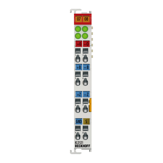
Product overview Product overview KL2521-xxxx - Introduction Fig. 1: KL2521 1 Channel Pulse Train Output Terminal The KL2521-xxxx output terminals change the frequency of a binary signal and output it (electrically isolated from the K-bus). The frequency is preset by a 16 bit value from the automation device. The output stage of the KL2521-0000 is RS422-compatible. -
Page 9: Kl2521-Xxxx - Technical Data
Process image In the delivery state the KL2521 terminal occupies 3 bytes in the process image. The mapping of the KL2521 can be set by means of the controller or by the Bus Coupler's configuration interface using the Beckhoff KS2000 configuration software. -
Page 10: Ramp Function
Product overview Operation modes In addition to the FM (frequency modulation) operation mode, the KL2521 can also be used to control stepper motors with pulse-direction control (frq. cnt pulse mode). Incremental encoder simulation is another operation mode. It is possible to connect the terminal output directly to an incremental encoder input, with which many servo drives and frequency converters are equipped. -
Page 11: Travel Distance Control
Product overview 2.3.2 Travel distance control If the travel distance control function is active (Feature.9), then a rising edge at Control.2 will result in drive to a fixed counter value. This value must previously be entered in register 0 (low word) and in register 1 (high word) at runtime. -
Page 12: Output Pattern
Product overview 2.3.3 Output pattern The pulse pattern is output through channels A and B. The operation mode is configured with the feature register R32. The operation modes differ primarily between the positive logic (modes 0, 1, 2) and the negative logic (modes 4, 5, 6). -
Page 13: Mounting And Wiring
Each assembly must be terminated at the right hand end with an EL9011 bus end cap, to ensure the protection class and ESD protection. Fig. 3: Spring contacts of the Beckhoff I/O components Installation on mounting rails Risk of electric shock and damage of device! -
Page 14: Fig. 4 Attaching On Mounting Rail
Mounting and wiring Assembly Fig. 4: Attaching on mounting rail The Bus Coupler and Bus Terminals are attached to commercially available 35 mm mounting rails (DIN rails according to EN 60715) by applying slight pressure: 1. First attach the Fieldbus Coupler to the mounting rail. 2. -
Page 15: Fig. 5 Disassembling Of Terminal
Mounting and wiring Disassembly Fig. 5: Disassembling of terminal Each terminal is secured by a lock on the mounting rail, which must be released for disassembly: 1. Pull the terminal by its orange-colored lugs approximately 1 cm away from the mounting rail. In doing so for this terminal the mounting rail lock is released automatically and you can pull the terminal out of the bus terminal block easily without excessive force. -
Page 16: Fig. 6 Power Contact On Left Side
Mounting and wiring Fig. 6: Power contact on left side Possible damage of the device Note that, for reasons of electromagnetic compatibility, the PE contacts are capacitatively coupled to the mounting rail. This may lead to incorrect results during insulation testing or Attention to damage on the terminal (e.g. -
Page 17: Installation Instructions For Enhanced Mechanical Load Capacity
Mounting and wiring Installation instructions for enhanced mechanical load capacity Risk of injury through electric shock and damage to the device! Bring the Bus Terminal system into a safe, de-energized state before starting mounting, disassembly or wiring of the Bus Terminals! WARNING Additional checks The terminals have undergone the following additional tests:... -
Page 18: Fig. 7 Standard Wiring
Mounting and wiring • The High Density Terminals (HD Terminals) include electronics and connection level in a single enclosure and have advanced packaging density. Standard wiring (ELxxxx / KLxxxx) Fig. 7: Standard wiring The terminals of ELxxxx and KLxxxx series have been tried and tested for years. They feature integrated screwless spring force technology for fast and simple assembly. -
Page 19: Wiring
Mounting and wiring The Bus Terminals from these series with 16 terminal points are distinguished by a particularly compact design, as the packaging density is twice as large as that of the standard 12 mm Bus Terminals. Massive conductors and conductors with a wire end sleeve can be inserted directly into the spring loaded terminal point without tools. -
Page 20: Shielding
Mounting and wiring See the following table for the suitable wire size width. Terminal housing ELxxxx, KLxxxx ESxxxx, KSxxxx Wire size width (single core wires) 0.08 ... 2.5 mm 0.08 ... 2.5 mm Wire size width (fine-wire conductors) 0.08 ... 2.5 mm 0,08 ... 2.5 mm Wire size width (conductors with a wire end sleeve) 0.14 ... -
Page 21: Kl2521-Xxxx - Connection And Led Description
Mounting and wiring KL2521-xxxx - Connection and LED description Risk of injury through electric shock and damage to the device! Bring the Bus Terminals system into a safe, de-energized state before starting mounting, disassembly or wiring of the Bus Terminals! WARNING Fig. 11: KL2521-xxxx - Connection and LEDs Connection of KL2521-xxxx... -
Page 22: Fig. 12 Internal Circuit Of The Inputs T And Z
Mounting and wiring Connecting the inputs (KL2521-0000, KL2521-0024) The optically isolated inputs are protected from overload by a current limiter. Without further external circuitry the operating voltage may lies between 5 V and 24 V . The GND connection is the common ground for the two inputs, T and Z. -
Page 23: Fig. 15 Kl2521-0000 Up To Hardware Version 03 - Wiring With External Power Source
Mounting and wiring Connection to optocoupler (with external supply voltage) For connection to inputs with a large input resistance, an external supply voltage (up to 24 V) can be used with the EL2521-0024 in order to create the necessary current. Operation with an external supply voltage is dependent on the hardware ver- sion The operation with an external supply voltage depends on the hardware version of the ter- Note... -
Page 24: Fig. 17 Kl2521-0024 - Connection To External Electronics
This allows the dual-channel connection of external electronics if the KL2521-0024 switches the ground of the connected device as shown in example 1. Notes on connection to external electronics • The Beckhoff KL5111, KL5121, KL5151 and KL5152 incremental encoder interface ter- minals require the switching of the positive voltage. Note •... -
Page 25: Atex - Special Conditions (Standard Temperature Range)
• EN 60079-0:2012+A11:2013 • EN 60079-15:2010 Marking The Beckhoff fieldbus components with standard temperature range certified for potentially explosive areas bear one of the following markings: II 3G KEMA 10ATEX0075 X Ex nA IIC T4 Gc Ta: 0 … 55°C II 3G KEMA 10ATEX0075 X Ex nC IIC T4 Gc Ta: 0 … 55°C KL2521 Version: 2.1... -
Page 26: Atex Documentation
Notes about operation of the Beckhoff terminal systems in potentially explo- sive areas (ATEX) Pay also attention to the continuative documentation Note Notes about operation of the Beckhoff terminal systems in potentially explosive areas (ATEX) that is available in the download area of the Beckhoff homepage http:\\www.beckhoff.com! Version: 2.1... -
Page 27: Configuration Software Ks2000
Configuration Software KS2000 Configuration Software KS2000 KS2000 - Introduction The KS2000 configuration software permits configuration, commissioning and parameterization of bus couplers, of the affiliated bus terminals and of Fieldbus Box Modules. The connection between bus coupler / Fieldbus Box Module and the PC is established by means of the serial configuration cable or the fieldbus. Fig. 20: KS2000 configuration software Configuration You can configure the Fieldbus stations with the Configuration Software KS2000 offline. - Page 28 Configuration Software KS2000 Commissioning The KS2000 software facilitates commissioning of machine components or their fieldbus stations: Configured settings can be transferred to the fieldbus modules by means of a download. After a login to the terminal station, it is possible to define settings in couplers, terminals and Fieldbus Box modules directly online. The same high-level dialogs and register access are available for this purpose as in the configuration phase.
-
Page 29: Access From The User Program
Access from the user program Access from the user program Process data Input format: • Two's complement representation (integer-1 equals 0xFFFF) or • Signed amount representation (Feature.3) (integer - 1 equals 0x8001) The output frequency is specified within maximum resolution of 15 bits (the 16 bit is used to specify the direction). -
Page 30: Register Overview
Access from the user program Register overview These registers exist once for each channel Address Name Default value Storage medium Target counter value (low word) 0x0000 (0 R0 [} 31] Target counter value (high word) 0x0000 (0 R1 [} 31] Maximum frequency 0x0000 (0 R2 [} 31] Counter extension (high word) -
Page 31: Register Description
Access from the user program Register description The registers can be read or written via the register communication. They are used for the parameterization of the terminal. R0 to R7: Registers in the internal RAM of the terminal The process variables can be used in addition to the actual process image. Their function is specific to the terminal. - Page 32 Access from the user program • R13: Data type register Data type register Meaning 0x00 Terminal with no valid data type 0x01 Byte array 0x02 Structure 1 byte n bytes 0x03 Word array 0x04 Structure 1 byte n words 0x05 Double word array 0x06 Structure 1 byte n double words...
- Page 33 Access from the user program • R32: Feature register [0x0030] This register specifies the operation modes of the terminal. Thus, for instance, a user-specific scaling can be enabled for the analog I/Os. Feature bit no. Description of the operation mode Bit 0…Bit1 No function Bit 2 [0] Watchdog timer active...
- Page 34 Access from the user program • R39: Base frequency 2 (high word) This register contains the high word of the base frequency 2. The base frequency 2 is used if ◦ the ramp function is deactivated and ◦ the Frequency_Selection bit (Control.0) is 1. •...
-
Page 35: Control And Status Byte
Access from the user program Control and status byte The control and status byte is transmitted from the controller to the terminal. It can be used • in register mode [} 36] (REG = 1 ) or • in process data exchange [} 35] (REG = 0 5.4.1 KL2521-0000, KL2521-0024 - Process data exchange Control byte in process data exchange (REG=0) -
Page 36: Kl2521-0010 - Process Data Exchange
Access from the user program 5.4.2 KL2521-0010 - Process data exchange Control byte in process data exchange (REG=0) Name Reg_Access SET_Z SET_T Cnt_Clr Go_Counter Ramp_Dis Freq_Sel Name Description Bit 7 Reg_Access Register communication inactive (process data exchange) bin: Bit 5 SET_Z Set output Z Bit 4... -
Page 37: Fig. 21 Register Mode Control Byte
Access from the user program Control byte in register mode (REG=1) REG=1 REG = 0 : Process data exchange REG = 1 : Access to register structure W/R = 0 : Read register W/R = 1 : Write register A5..A0 = register address Addresses A5...A0 can be used to address a total of 64 registers. -
Page 38: Examples Of Register Communication
Access from the user program Byte Byte 3 Byte 2 Byte 1 Byte 0 Name Data out, low byte Data out, high byte Not used Control byte Value 0x35 0x12 0xXX 0xDF The code word [} 32] is set, and the terminal returns the register address with bit 7 for register access as acknowledgment. - Page 39 Access from the user program I. Write the code word (0x1235) into Register 31. Output Data Byte 0: Control byte Byte 1: DataOUT1, high byte Byte 2: DataOUT1, low byte 0xDF (1101 1111 0x12 0x35 Explanation: • Bit 0.7 set means: Register communication switched on. •...
- Page 40 Access from the user program • Bit 0.7 set means: Register communication switched on. • Bit 0.6 set means: writing to the register. • Bits 0.5 to 0.0 indicate register number 32 with 10 0000 • The output data word (byte 1 and byte 2) contains the new value for the feature register. Observe the register description! The value of 0x0002 given here is just an example! The bits of the feature register change the properties of the terminal and have a different...
- Page 41 Access from the user program • Bits 0.5 to 0.0 specify the register number 31 with 01 1111 • The output data word (byte 1 and byte 2) contains 0x0000 for reactivating write protection. Input Data (answer of the bus terminal) Byte 0: Status byte Byte 1: DataIN1, high byte Byte 2: DataIN1, low byte...
-
Page 42: Appendix
Beckhoff's branch offices and representatives Please contact your Beckhoff branch office or representative for local support and service on Beckhoff products! The addresses of Beckhoff's branch offices and representatives round the world can be found on her internet pages: http://www.beckhoff.com You will also find further documentation for Beckhoff components there. - Page 43 List of illustrations Fig. 1 KL2521 ............................Fig. 2 Phases of the travel distance control................... Fig. 3 Spring contacts of the Beckhoff I/O components................. Fig. 4 Attaching on mounting rail ......................Fig. 5 Disassembling of terminal......................Fig. 6 Power contact on left side......................
Need help?
Do you have a question about the KL2521 Series and is the answer not in the manual?
Questions and answers