Table of Contents
Advertisement
Quick Links
Advertisement
Table of Contents

Related Manuals for CellScale BioTester


Summary of Contents for CellScale BioTester
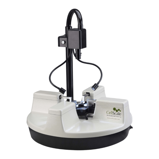
- Page 1 BioTester User Manual BioTester Biaxial Test System User Manual version 7.6...
- Page 2 © 2017 CellScale. All rights reserved. This material may not be reproduced, displayed, modified or distributed without the express prior written permission of the copyright holder. For permission, contact CellScale Biomaterials Testing at info@cellscale.com.
-
Page 3: Table Of Contents
BioTester User Manual Table of Contents General Information ....................... 1 Environmental and Electrical Specifications ................1 System Assembly ........................1 Power Connections ........................1 Safety Warnings ........................1 Approvals and Certification ....................... 1 Manual Operating Controls ....................... 2 Software ........................... 2 General Maintenance........................ - Page 4 10. Appendix A: Initial System Setup ..................45 Tools ............................45 Fasteners & Parts ........................45 Unpack System ........................46 Remove the BioTester from the shipping container ..............46 Attach Camera Mast ........................47 Place Fluid Chamber on Riser Stage ..................49 Install Camera Lens .........................50 11. Appendix B: Software Installation ..................51 12.
- Page 5 BioTester User Manual Stow Cables and Plug in the Load Cells ..................65 Attach the Temperature Probe ....................67 Attach the Knob to the Pull Rod ....................67 Turn on the BioTester ......................67 Launch the LabJoy Software ....................68 Perform Camera Alignment......................71 Perform Vertical Gooseneck Alignment..................74 Perform Transverse and Axial Gooseneck Alignment ..............76...
-
Page 6: General Information
BioTester User Manual 1. General Information The BioTester is a precision test instrument specifically designed for the measurement and analysis of small biological specimens. The system includes a compact biaxial test station and an integrated software interface to run and analyze test results. The system is intended for indoor use only. -
Page 7: Manual Operating Controls
Software LabJoy software is included and is required to run the BioTester. 2 x USB ports are required for data connections. Windows 7 or higher is required to run LabJoy. -
Page 8: Testing Terminology
BioTester User Manual 2. Testing Terminology The BioTester is designed to apply biaxial forces to soft tissue specimens (deforms by more than 1% in vivo) with an in-plane dimension of 3 - 15 mm. This includes biological material such as eye tissue, heart valves, pericardium, joint capsules, large blood vessels, scaffolds, and polymers. -
Page 9: Phases, Cycles, And Test Sequences
BioTester User Manual Phases, Cycles, and Test Sequences As the following diagram demonstrates, each application and release of load on the specimen is called a test cycle. The same test cycle can be repeated multiple times to achieve a certain goal (preconditioning, physiological conditioning, or testing);... -
Page 10: Test Phases: The Smallest Unit Of Testing
Several control functions are available for displacement control. Under force control, the force applied to the specimen is predefined. The BioTester stretches the specimen until the predefined force is achieved. The displacement required to achieve the force is an output of the test. -
Page 11: Control Functions
BioTester User Manual Control Functions The BioTester makes it possible to test specimens under several control functions: Under displacement control: The true strain function applies the displacement at a constant true strain rate, which accounts for the current specimen length while the specimen is being stretched. -
Page 12: System Overview
BioTester User Manual 3. System Overview System Components The BioTester brings together several high-precision components, making it the state-of-the-art instrument for testing biomaterials. High resolution camera provides synchronized video tracking and analysis. Illumination and lens provided to capture excellent image quality. -
Page 13: Software Overview
BioTester User Manual Software Overview The software included with the BioTester is called LabJoy. It is divided into two modules, a data collection module and a review and analysis module. The data collection module is used to set test parameters, enable specimen loading and testing, and monitor test progress. The screen... -
Page 14: Output Files And Data Structures
BioTester User Manual Output Files and Data Structures For each test, the BioTester creates and saves three file types. The following table describes the three file types for a project named “Sample1”. Output from this test would be found in a “Sample1”... -
Page 15: Setting Up & Starting A Test
In the Create Test from Template dialogue, perform the following steps: 1. Select a template that matches the type of test you wish to perform. See the BioTester Tip on how to select and use a template. You can modify the template parameters in Step 4, below. -
Page 16: Step 2: Reset The Actuators
BioTester User Manual BioTester Tip: Selecting and Using Templates How to select a template: Designing an appropriate test sequence is an art that depends on both the type of material being tested and the specific material properties you are interested in measuring. When first testing a new material, you should expect to have to experiment with the settings until the test yields meaningful data. -
Page 17: Step 3: Move The Actuators To A Specified Size
BioTester User Manual System Alert The actuators SHOULD NOT be reset if the specimen is already mounted. Doing so will damage your specimen as well as possibly damage the BioRakes or Load Cells. Step 3: Move the Actuators to a Specified Size After the actuators have been reset, they will remain in their fully retracted positions and must be moved to specified (reference or starting) positions. -
Page 18: Step 5: Modify Testing Parameters (Optional)
BioTester User Manual Step 5: Modify Testing Parameters (optional) You can select and modify parameter sets by clicking on their row in the Test Sequence table and then pressing the Edit Set button (or by double clicking on their row). When you do so, the Set Parameter Editor dialogue will appear. - Page 19 BioTester User Manual Test Parameter Description Control Mode Biaxial tests are typically performed under displacement control, however, you can select the following control modes to achieve specific testing objectives: • To obtain uniaxial properties for a biaxially mounted specimen, specify displacement control in one axis and Force control with zero Load Magnitude in the other axis.
-
Page 20: Step 6: Mount The Specimen
BioTester User Manual Step 6: Mount the Specimen Proper specimen mounting is critical to ensuring accurate and repeatable results. It is best to have the tines spaced evenly across the edge of the specimen and as closely to the edges as possible. - Page 21 BioTester User Manual...
-
Page 22: Step 7: Execute The Test
BioTester User Manual BioTester Tip: Ideal Specimen Size The BioTester is designed for small specimen sizes. For Standard BioRakes (5 tines spaced at 1 mm) the ideal specimen size is square with side lengths of 5.5 - 6 mm. If a specimen is not in the ideal range, it may still be mounted, but the placement of the rake tips will need to be adjusted. -
Page 23: Additional Settings
BioTester User Manual 5. Additional Settings Configuring Output Data Files From the Settings menu, select Data Output to display the dialogue shown on the left. Click the Configure button to select which of the following columns to output. → Output Column... -
Page 24: Advanced System Settings Dialogue
BioTester User Manual Advanced System Settings Dialogue Advanced settings are available by selecting Advanced from the Settings menu. All of these settings are template specific. True Strain Rate Unlike nominal or engineering strain rate, a plot of velocity versus time for a true strain rate test would be non-linear. - Page 25 Tools menu select Move Actuators to Specified Load. The dialogue shown on the right will appear. The BioTester will attempt to achieve the specified loads (forces) but will stop when either the specified loads are reached, the actuators have displaced by the maximum specified amount, or the timeout time has elapsed.
-
Page 26: Range Limits
BioTester User Manual Range Limits Range limits can be accessed by selecting Range Limits from the Settings menu. Soft Limits To avoid rake collisions or sample destruction, useful assign reasonable travel limits to the actuators. This is especially important during force... -
Page 27: Configuring The Live Charting Graphs
BioTester User Manual Configuring the Live Charting Graphs The three graphs on the right side of the screen provide real-time user feedback during a test. These graphs are intended to be used for qualitative feedback, not for detailed analysis. The graphs are updated at a maximum frequency of 10Hz;... - Page 28 BioTester User Manual Graph Data Force versus Time This graph shows how the measured X and Y forces are changing with time. Peak loads per cycle, differences in load between the X and Y axes, and force relaxation are all easily seen in this type of graph.
-
Page 29: Reviewing Test Results
6. Reviewing Test Results Overview The BioTester software has an integrated image analysis module which can be accessed by selecting Analyze and Review Images from the File menu, then selecting the appropriate test file. The test file is a text file with a .tst extension that contains information about the test parameters so that the software can display the images and data in a useful fashion. -
Page 30: Selecting Images
BioTester User Manual Selecting Images The Images are shown in a tree structure on the top left panel. The tree structure organizes the images by: Set (line on the Test Sequence window) Cycle (iteration of a given Set) Phase (Preload/Stretch/Hold/Recovery/Rest of each Cycle) -
Page 31: Image Tracking: Overview
BioTester User Manual Image Tracking: Overview Image tracking is a function that can be used to quantify the motions of image features (rake tines, specimen texture and fiducial markers). This can be useful for studying localized specimen deformations, verifying strain magnitudes, comparing the results of one test to another. - Page 32 BioTester User Manual 6. Modify search parameters: Source The optimal source template is difficult to predict, but in general it is Template advantageous for the template to be large enough that it contains at least one feature, but not so large that it contains multiple features.
-
Page 33: Image Tracking: The Points Display Option
BioTester User Manual Image Tracking: The Points Display Option The Points Option displays the points in their current location (i.e. their location on the currently displayed image) with or without gridline connecting points that were generated using the grid function. -
Page 34: Image Tracking: The Displacement Option
BioTester User Manual Image Tracking: The Displacement Option The Displacement Option displays the points in their current location as well as graphically representing their motion through time. Clicking the details icon brings up the window shown to the right. This dialogue allows the user to change the reference image, change the type of connecting line, and change the line appearance. -
Page 35: Image Tracking: The Strains Option
BioTester User Manual Image Tracking: The Strains Option The Strains Option can only be used in conjunction with a grid of points (as opposed to individually placed points). This option calculates the regional strains inside every grid box and displays this data as an ellipse. -
Page 36: Data Overlay
BioTester User Manual Data Overlay Data associated with each image is displayed below the tracking controls on the left side of the main window. Checking the Show Graph box displays this data as a graph overlaid on the images Clicking the details icon displays the window shown to the right. -
Page 37: Exporting Tracked Data
BioTester User Manual Exporting Tracked Data Tracked grid point coordinates and calculated grid strains can be exported to a .csv file. From the Export menu, select Data Points to display the dialogue shown on the right. The image list is automatically set to the currently selected images in the test image list tree. -
Page 38: Exporting Images And Movies
Once the images have been imported, the software works much the same as with BioTester- generated images. -
Page 39: System Hardware Settings
BioTester User Manual 7. System Hardware Settings Controller The BioTester uses an integrated control board rather than a group of PC controlled device drivers. This minimizes communication lag and allows the device to operate asynchronously with the PC. The control board... -
Page 40: Load Cells
BioTester User Manual Load Cells The load cells are semiconductor strain gage-based with mechanical overload protection (for the lower capacity load cells). They have accuracy equal to 0.2% of the rated full scale load. The load cells are available in 0.5N, 1N, 2.5N, 5N, 10N and 23N sizes. Each load cell has a unique calibration factor which is stored in a chip attached to the load cell connector. -
Page 41: Temperature
Temperature To activate the fluid chamber heater, both power switches on the front of the BioTester need to be in the On position (the computer and software do not need to be on yet). At this point, the heater will warm the fluid to the last used temperature set point. -
Page 42: External Sync Pulse
BioTester User Manual External Sync Pulse A 5 volt TTL external sync pulse signal can be generated on BioTester models containing a BNC connector jack on the back panel. The sync pulse will be pulsed on the very first sample pulse, which occurs when the load cells are measured and the motor positions of all 4 axes are read. -
Page 43: System Calibration And Advanced Tools
BioTester User Manual 8. System Calibration and Advanced Tools Load Cell Calibration If the load cells are changed, moved, or impacted, it is good practice to perform the load cell calibration routine. This calibration can be performed in the following steps: 1. - Page 44 BioTester User Manual 7. Using the Jog+ and Jog– buttons, move the actuators until the spring is carrying a tension that is out of the non- linear “dead zone” and reaches the appropriate preload. The current force reading for each axis is displayed in the lower left of the LabJoy main screen.
-
Page 45: Snap Image Feature
BioTester User Manual 10. The number (A) that is displayed in the main dialogue box at the end of the calibration procedure is the ratio of the current calibration value to the previous calibration value. If there has been no change to the load cell, A should be between 0.99 and 1.01. -
Page 46: Adjusting The Camera Position And Image Magnification
The BioTester comes equipped with a 10X zoom lens as shown below. Other versions of the BioTester may be equipped with a fixed magnification 75mm focal length lens (see Appendix E). - Page 47 BioTester User Manual Map Field of View to Working Distance Minimum Magnification Maximum Magnification Working Distance (cm)
-
Page 48: Update Firmware
BioTester User Manual Update Firmware 1. With the BioTester connected to the PC and turned on, launch the firmware update software located in the Windows start menu under LabJoy>Utilities. 2. Load the firmware file using the “Load Update File” button. -
Page 49: Troubleshooting
When a communication error occurs, close LabJoy, check connections, power cycle the BioTester, and restart LabJoy. BioTester Tip: Preventing Power Disruptions We recommend plugging the BioTester (and host computer) into an uninterruptable power supply (UPS) or battery back-up. Zero Displacement Causes Software Crash Under certain conditions involving preloads and cyclic loading, the software may crash if a test phase has zero displacement in one axis. -
Page 50: Appendix A: Initial System Setup
BioTester User Manual 10. Appendix A: Initial System Setup The BioTester has been packed in a special container to protect it during shipping. In addition, system accessories have been packed in several cartons contained in a separate box. The system components listed below may be unpacked and laid out before system setup. A space 60cm x 60cm with 100cm overhead clearance is required for setup. -
Page 51: Unpack System
BioTester can be lifted out. One person should lift the camera mast while the other lifts out the BioTester main unit. Take special care with the camera mast as it is connected to the main unit by 2 cables. In addition, protective foam will have to be removed from... -
Page 52: Attach Camera Mast
BioTester User Manual Attach Camera Mast Thread the camera post into the receiver. The knurled collar must be rotated to fasten the camera post. It will take many turns but eventually the mast will lock into place. Try to position the camera approximately as shown, although the final position can be adjusted later in the procedure. - Page 53 BioTester User Manual Once the camera mast is in place, tuck the remaining lighting power cable underneath the cover beside the linear actuator.
-
Page 54: Place Fluid Chamber On Riser Stage
BioTester User Manual Place Fluid Chamber on Riser Stage Put the fluid chamber in place on the riser stage and align the temperature probe mounting hole with the temperature probe cable. -
Page 55: Install Camera Lens
BioTester User Manual Install Camera Lens Remove the protective caps on the lens and camera body and then screw the lens and spacer tube onto the camera . The 5mm spacer tubes come attached to the camera and lens from the production facility. -
Page 56: Appendix B: Software Installation
A Windows based PC (Windows 7 or above) with at least 2 USB ports is required to operate the BioTester. A label on the cover of the manual contains a web address to download the LabJoy installation package. These files contain the software installer for LabJoy, which is the user interface and control software for the BioTester. - Page 57 BioTester User Manual...
- Page 58 BioTester User Manual...
- Page 59 BioTester User Manual...
- Page 60 BioTester User Manual...
- Page 61 BioTester User Manual...
-
Page 62: Appendix C: Install Load Cells / Perform Camera And Gooseneck Alignment
Connect the camera USB cable to a PC USB port. Connect the included USB cable to the main unit and a PC USB port. Plug in the power supply to the BioTester and then proceed with the following steps. Do not turn the BioTester on yet. - Page 63 BioTester User Manual Attach the load cell stud to the load cell using your fingers. The load cell stud has one side with a shoulder below the threads which should be attached to the load cell. The other end is attached to the gooseneck.
- Page 64 BioTester User Manual Attach the other end of the load cell stud to the gooseneck. Finger tighten a 6-32 nut onto the threaded stud. The load cell cable should be at about a 45° angle to the gooseneck as shown...
- Page 65 Check that all components are snugly in place by gently turning the base of the load cell against the gooseneck. All components should be finger tight while being snug enough so that the components don’t freely rotate while using the BioTester.
-
Page 66: Attach The Load Cell Brackets To The Actuators
BioTester User Manual Attach the Load Cell Brackets to the Actuators Before attaching the load cell/gooseneck assembly, install the load cell brackets onto the appropriate actuators (these are located on either side of the camera post and will be sitting lower... -
Page 67: Attach The Goosenecks To The Actuators
BioTester User Manual Attach the Goosenecks to the Actuators Attach each load cell/gooseneck assembly to the load cell bracket on the appropriate linear actuator using a 6-32 nut. The load cells are attached to the actuators on either side of the camera post. - Page 68 BioTester User Manual...
- Page 69 BioTester User Manual Attach the 2 remaining goosenecks to the appropriate linear actuators using 6-32 x ½” fasteners (x4 each).
-
Page 70: Stow Cables And Plug In The Load Cells
Also, the load cells may have a coiled length of cable which must be carefully stowed. The initial length of cable should bend towards the outside edge of the BioTester as shown. Position the cables inside the cover so that they do not interfere with the actuator carriage travel, particularly during actuator reset where the carriages are fully retracted. - Page 71 BioTester User Manual...
-
Page 72: Attach The Temperature Probe
Attach the temperature probe and place it in the sensor pocket in the fluid chamber. Attach the Knob to the Pull Rod A small knob screws into the pull rod at the front of the BioTester. This pull rod is used to raise and lower the stage. -
Page 73: Launch The Labjoy Software
BioTester User Manual Launch the LabJoy Software Launch the LabJoy software. The default screen should appear as: Selecting File>Collect New should bring up this window:... - Page 74 Select OK. If prompted to Reset Actuators, select “Yes”. If prompted to Calibrate Load Cells, select “No”. Next place a standard size BioRake (1.0mm spacing, blue caps) in each of the 4 goosenecks so that the BioTester looks like this:...
- Page 75 BioTester User Manual On the LabJoy control screen, ensure that the specimen size is set to 5000µm in X and Y and then click the Move to Size button...
-
Page 76: Perform Camera Alignment
BioTester User Manual Perform Camera Alignment The camera position has both coarse and fine position adjustments and coarse and fine focus adjustments. To start, loosen the fasteners which tighten to camera cover to the mast. Position the camera cover vertically such that the working distance from the lens surface to the BioRakes is 15cm. - Page 77 BioTester User Manual Attempt to bring all of the BioRakes into the image, as shown below: Next, fine tune the camera position using the knobs at the back and side of the camera housing and fine tune the image focus using the lowest ring on the lens.
- Page 78 BioTester User Manual Iris (fully open) Zoom Focus Adjustments to the zoom can be made by adjusting the middle ring on the lens. See the section on “Adjusting the Camera Position and Image Magnification” in section 8 of this manual for more...
-
Page 79: Perform Vertical Gooseneck Alignment
BioTester User Manual Perform Vertical Gooseneck Alignment Because the goosenecks attached to the load cells are connected by only 1 threaded stud, the vertical and transverse alignment of the end of the gooseneck can be somewhat different each time the goosenecks are removed and reattached. To accommodate the vertical variation, shims between the gooseneck brackets and the actuators may need to be added or removed. - Page 80 BioTester User Manual By looking at the BioRakes from the side, it is possible to observe their vertical alignment. Please add or remove shims to vertically align the BioRakes. Here are photos of poor vertical alignment and good vertical alignment:...
-
Page 81: Perform Transverse And Axial Gooseneck Alignment
BioTester User Manual Perform Transverse and Axial Gooseneck Alignment This step requires 2 different adjustment mechanisms. The goal is to make the BioRakes look like this: First, make sure the BioRakes are positioned in the transverse center of the gooseneck. The magnetic mounts that hold the BioRakes to the gooseneck fix them in the axial direction, but allow a small amount of adjustment in the transverse direction. - Page 82 BioTester User Manual To transversely adjust the goosenecks, loosen the fasteners that attach the goosenecks to the actuators, slightly rotate the gooseneck, and retighten the fasteners. The on-screen image should be helpful as a guide. The goal is to make the rake tines of opposing BioRakes collinear.
- Page 83 BioTester User Manual Example 1: BioRakes have too much overlap. Example 2: BioRakes are correctly positioned. Example 3: BioRakes do not have any overlap so tips are not collinear.
- Page 84 BioTester User Manual 8. Remove the BioRakes and place them on the Y axis. 9. Using the actuator control arrows, drive the Y actuators until all 10 BioRake tips are collinear as in step 4 (IN MIRROR MATCHING MODE ONLY!).
-
Page 85: Install Actuator Covers
BioTester User Manual Install Actuator Covers Each actuator cover has a number written on the inside. These numbers match up with numbers written on the inside of the main cover to ensure the best possible fit between the actuator covers and the main cover. -
Page 86: Appendix D: Mechanical Grip Usage
BioTester User Manual 13. Appendix D: Mechanical Grip Usage Installing Grips In addition to BioRakes, the BioTester can optionally be equipped with mechanical grips for sample attachment. The mechanical grips can be equipped with three different springs of varying stiffness to exert different gripping forces. -
Page 87: Sample Mounting
BioTester User Manual Sample Mounting Squeeze the grip levers to open the jaws of the grip. Slide the end of a test specimen between the jaws and gently release the levers. Specimens may be mounted and tested using 2 grips... - Page 88 BioTester User Manual System Alert When squeezing the grip levers to open the jaws, exert force as much as possible in a linear direction through the body of the load cell to avoid off-axis or bending forces. Figure 9 - Uniaxial Test Setup...
-
Page 89: Changing Grip Springs
BioTester User Manual Changing Grip Springs 1. Using the hook tool provided, pull on the spring and remove the metal dowel holding the grip spring in place. After this step, the spring may be slowly released. System Alert A fully installed spring experiences a high amount of tension. When the springs are disengaged, be sure not to let the hook tool slip or the spring may be released at high velocity. - Page 90 BioTester User Manual 2. Replace the old spring with a new spring inside the mounting hole. 3. Secure one side of the spring onto the grip with the metal dowel 4. Use the hook tool to pull the other side of the spring into place and secure it with another...
-
Page 91: Appendix E: Fixed Focal Length Lens
14. Appendix E: Fixed Focal Length Lens In addition to the 10X zoom lens described in Section 8, the BioTester system can also use fixed focal length lenses. Other BioTester models may have a 75mm focal length lens and a set of lens spacers. -
Page 92: Adjusting Camera Position And Image Magnification
BioTester User Manual Adjusting Camera Position and Image Magnification The camera position can be adjusted using the knobs at the back and side of the camera housing. If larger position adjustments are needed, the bolts that attach the camera to the mast can be loosened to allow rotation of the camera housing. - Page 93 BioTester User Manual 25mm (NT56-529) 35mm (NT56-530) 50mm (NT56-531) 75mm (NT56-532) 100mm (NT56-675) Stand Stand Stand Stand Stand Spacer pix/c pix/c pix/c pix/c pix/c (mm) (mm) (mm) (mm) (mm) (mm) (mm) (mm) (mm) (mm) (mm) 685 78.6 162.8 1070 71 179.3 930 121 105.9...
-
Page 94: Appendix F: Protocol For Tying And Cutting Sutures For Biaxial Testing
15. Appendix F: Protocol for Tying and Cutting Sutures for Biaxial Testing In addition to BioRakes and grips, the BioTester can optionally be equipped with bracket and pulley system to attach samples using sutures. There are many ways to attach specimens to the suture brackets using a variety of suture designs. - Page 95 BioTester User Manual 2. Bend suture hooks...
- Page 96 BioTester User Manual 3. Tie off sutures. First hook each bent hook around a secured post held in the vice. Then tie a standard knot in the suture and use forceps to guide the location of the knot so that...
- Page 97 BioTester User Manual...
- Page 98 BioTester User Manual 4. Use pliers to tighten knot...
- Page 99 BioTester User Manual 5. Cut off excess.
- Page 100 BioTester User Manual The resulting mounted specimen should ideally look something like this: © Copyright 2017 CellScale Biomaterials Testing.
Need help?
Do you have a question about the BioTester and is the answer not in the manual?
Questions and answers