Table of Contents
Advertisement
Quick Links
Advertisement
Table of Contents

Related Manuals for CellScale UniVert


Summary of Contents for CellScale UniVert
- Page 1 UniVert Mechanical Test System User Manual version 3.0...
- Page 2 © 2021 CellScale. All rights reserved. This material may not be reproduced, displayed, modified, or distributed without the express prior written permission of the copyright holder. For permission, contact CellScale Biomaterials Testing at info@cellscale.com.
-
Page 3: Table Of Contents
Table of Contents General Information ......................... 1 Environmental and Electrical Specifications ................1 System Assembly......................... 1 Connections to Supply ......................... 1 Safety Warnings ........................... 2 Manual Operating Controls ......................2 General Maintenance ........................2 Approvals and Certification ......................2 Testing Terminology ........................3 Multiphase Test Cycles ........................ - Page 4 Force Control Settings ......................23 Force and Displacement Control Settings ................24 System Stiffness Compensation .................... 24 Range Limits ..........................25 Configuring the Live Charting Graphs ..................26 Reviewing Test Results ......................... 28 Overview ............................ 28 Selecting Images........................29 Image Playback Options ......................29 Image Tracking: Overview ......................
- Page 5 Components ..........................61 Fasteners ........................... 65 Appendix B: Load Cell Installation ....................70 Appendix C: Software Installation....................72 Appendix D: Test Setup ......................... 78 Tension Test Setup ........................78 Vertical Configuration ......................79 Horizontal Configuration ......................82 Compression Test Setup ......................85 Vertical Configuration ......................
-
Page 6: General Information
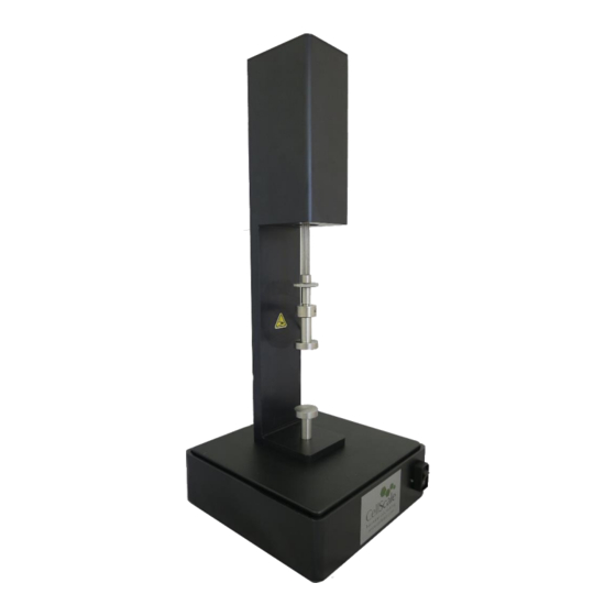
UniVert User Manual General Information The UniVert is a precision test instrument designed for the compressive and tensile testing and analysis of materials including polymers, biological specimens, and 3D-printed constructs. The UniVert system includes a test station and an integrated software interface to run and analyze test results. -
Page 7: Safety Warnings
Manual Operating Controls There are 2 manual switches on the front of the baseplate. The main power switch of the UniVert system is the leftmost switch (activating a green LED) and the Emergency stop switch (E-stop) is rightmost. -
Page 8: Testing Terminology
UniVert User Manual Testing Terminology The UniVert is designed to apply uniaxial compressive and tensile forces to a variety of materials. This includes soft metals, plastics, and composites as well as biological materials. Multiphase Test Cycles In order to properly characterize and test a specimen, it is often necessary to load it to different degrees and at different rates. -
Page 9: Phases, Cycles, And Test Sequences
UniVert User Manual Phases, Cycles, and Test Sequences As the following diagram demonstrates, each application and release of load on the specimen is called a test cycle. The same test cycle can be repeated multiple times to achieve a certain goal (preconditioning, physiological conditioning, or testing);... -
Page 10: Test Phases: The Smallest Unit Of Testing
(specified in mm or %). The force required to achieve the displacement is an output of the test. Under force control, the force applied to the specimen is predefined. The UniVert stretches or compresses the specimen until the predefined force is achieved (specified in... -
Page 11: Control Functions
The true strain function applies the displacement at a true strain rate, which accounts for the current specimen length while the specimen is being stretched and continuously recalculates the velocity. The UniVert system approximates this with a series of linear segments. -
Page 12: Test Modes And System Configurations
In this mode, positive displacement is in the direction of decreased fixture separation and compressive forces are positive. The UniVert can be used in two configurations: vertical and horizontal (see Appendix D for more details). The above test modes are all compatible in both configurations. For compression... -
Page 13: Software Overview
UniVert User Manual Software Overview The software included with the UniVert device is called UniVert. It is divided into several modules: a data collection module and an image review and analysis module as well as test template review. The data collection module is used to set test parameters, enable specimen loading and testing, and monitor test progress. -
Page 14: Output Files And Data Structures
UniVert User Manual Output Files and Data Structures For each test, the UniVert creates and saves three file types. The following table describes the three file types for a project named “Sample1”. Output from this test would be found in a “Sample1”... -
Page 15: Setting Up & Starting A Test
Step 8: Terminate the Test Prematurely (optional) Step 9: Saving the Template (optional) If this is your first time setting up the UniVert system, please complete the steps in Appendix A: Unpacking and Initial Setup prior to executing a test. -
Page 16: Step 2: Reset The Actuator
In the Create Test From Template dialog, perform the following steps: 1. Select a template that matches the type of test you wish to perform. See the below UniVert Tip on how to select and use a template. You can modify the template parameters in Step 5 below. -
Page 17: Step 3: Specify Test Type
UniVert User Manual Step 3: Specify Test Type Access Test Mode in the Settings menu to select the appropriate test mode and install the platens, grips, or 3-point bend attachments (see Appendix D for this procedure). Step 4: Zero the Load Cell (occasionally) While it is not necessary to zero the load cell with every test sequence, we suggest zeroing the load cell at the start of a new test session. -
Page 18: Step 5: Modify Testing Parameters (Optional)
UniVert User Manual Step 5: Modify Testing Parameters (optional) You can select and modify the parameters in the test sets by clicking on a row in the Test Sequence table and then pressing the Edit Set button (or by double clicking on the desired row). - Page 19 UniVert User Manual Test Parameter Description Control Mode Tests are performed under displacement or force control, however, you can select the following control modes to achieve specific testing objectives: • For creep testing, use force control with a long hold duration.
-
Page 20: Step 6: Mounting A Specimen
Ensure the correct size value is entered before clicking UniVert Tip: Compression Specimen Mounting Make sure to center the specimen on the platen as much as possible to ensure accuracy in the force reading. Ideally, specimens will have two parallel flat sides and will make full contact with both platens. -
Page 21: Grip Mounted Specimens
5. Open the bottom grip and lower the specimen between the grip surfaces. Release the bottom grip. UniVert Tip: Specimen Thickness Measuring the specimen thickness before and/or after a test is performed will allow stress calculations to be made from your output data. - Page 22 UniVert User Manual High Force Grips 1. Select a spring with an appropriate clamping force for the specimen being tested (see Appendix G for more details). 2. Jog the actuator using Actuator Control or select Move to Specified Size until the grips are sufficiently far apart.
-
Page 23: 3-Point Bend Specimens
UniVert User Manual 3-Point Bend Specimens 1. Choose the appropriate 3-Point Bend dowel for the type of test you wish to perform. 2. Install the 3-Point Bending test setup (See Appendix D) 3. Move the sliders into desired position and lock in place by tightening the 4-40 fastener to the rail using a 3/32”... -
Page 24: Step 7: Execute The Test
The displacement position cannot be stored if the E-Stop has been depressed. Once the UniVert is ready to be used again, twist the E-Stop to return it to its original position. A new test cannot begin until the E-Stop has returned to its original position. The actuator will need to be reset to restore the position. -
Page 25: Step 9: Saving The Template (Optional)
UniVert User Manual Step 9: Saving the Template (optional) At the end of the test (or before beginning the test), you may save the test parameters entered as a new template. Select Save as Template from the File menu. The Save Test as Template window will appear. -
Page 26: Additional Settings
UniVert User Manual Additional Settings Configuring Output Data Files From the Settings menu, select Data Output to display the dialogue shown on the left. Click the Configure button to select which of the following columns to output. Output Column Description... -
Page 27: Advanced System Settings Dialogue
UniVert User Manual Advanced System Settings Dialogue Advanced Settings are available by selecting Advanced from the Settings menu. All these settings are specific to the test template selected. Data Averaging The load cells are sampled at 100Hz with hardware using a central moving average of 8 samples. -
Page 28: Force Control Settings
Tools menu select Move Actuators to Specified Load. The dialogue shown on the right will appear. The UniVert will attempt to achieve the specified load (force) but will stop when the specified load is reached, the actuator has displaced by the maximum specified amount, or the timeout time has elapsed. -
Page 29: Force And Displacement Control Settings
System Stiffness Compensation System Stiffness Compensation can be used to compensate displacement readings that occur in the UniVert system during testing typically at high loads with low displacements. Under most loading conditions these displacements are negligible and system stiffness compensation is not required. -
Page 30: Range Limits
UniVert User Manual Range Limits Range limits can be accessed by selecting Range Limits from the Settings menu. Soft Range Limits To avoid collisions or sample destruction, it is useful to assign reasonable travel limits to the actuators. This is especially important during force control or preloading, where if specified loads cannot be reached, the actuators will keep moving until they reach the soft limits. -
Page 31: Configuring The Live Charting Graphs
UniVert User Manual Configuring the Live Charting Graphs The three graphs on the right side of the screen provide real-time user feedback during a test. These graphs are intended to be used for qualitative feedback, not for detailed analysis. The graphs are updated at a maximum frequency of 10Hz; certain short-duration tests may not show all the detail that is present. - Page 32 UniVert User Manual Graph Data Force versus Time This graph shows how the measured forces are changing with time. Peak loads per cycle and force relaxation are all easily seen in this type of graph. Force is proportional to nominal (engineering) stress.
-
Page 33: Reviewing Test Results
The basic UniVert system comes with a Logitech HD 1080p webcam intended to be used for recording images for image playback and review. This camera and software associated with it does not support image tracking. -
Page 34: Selecting Images
UniVert User Manual Selecting Images The Images are shown in a tree structure on the top left panel. The tree structure organizes the images by: Set (line on the test parameter window) Cycle (iteration of a given Set) Phase (Preload/Stretch/Hold/Recovery/Rest phase of each... -
Page 35: Image Tracking: Overview
UniVert User Manual Image Tracking: Overview Image tracking is a function that can be used to quantify the motions of image features (specimen texture and fiducial markers). This can be useful for studying localized specimen deformations, verifying strain magnitudes, and comparing the results of one test to another. - Page 36 UniVert User Manual...
- Page 37 UniVert User Manual 6. Modify search parameters: Source The optimal source template is difficult to predict, but in general it is advantageous for the template to be large enough that it contains at Template least one feature, but not so large that it contains multiple features.
-
Page 38: Image Tracking: The Points Display Option
UniVert User Manual Image Tracking: The Points Display Option The Points option displays the points in their current location (i.e. their location on the currently displayed image) with or without gridline connecting points that were generated using the grid function. -
Page 39: Camera
UniVert User Manual Camera The UniVert software can be equipped with the standard webcam package, the scientific camera package, or no camera at all. The software will automatically detect which camera configuration is in use. Webcam Package The basic UniVert system comes with a Logitech HD 1080p webcam intended to be used for recording images for image playback and review. -
Page 40: Image Tracking: The Displacement Option
UniVert User Manual Scientific Camera Package The advanced scientific camera package is not included with the base UniVert system and is available as an added feature. This advanced option provides high quality images suitable for image tracking and the associated software is enabled with the image tracking feature (See the Reviewing Test Results: Image Tracking section above). -
Page 41: Image Tracking: The Strains Option
UniVert User Manual Figure 3: Tracking to 33% strain displayed as displacement. Image Tracking: The Strains Option The Strains Option can only be used in conjunction with a grid of points (as opposed to individually placed points). This option calculates the regional strains inside every grid box and displays this data as an ellipse. -
Page 42: Data Overlay
UniVert User Manual Figure 4: Tracking to 33% strain displayed as strain ellipses with text showing x% strain. Data Overlay Data associated with each image is displayed below the tracking controls on the left side of the main window. Checking the Show Graph box displays this... -
Page 43: Exporting Tracked Data
UniVert User Manual Figure 5: Tracking to 33% strain with overlaid force graph. Exporting Tracked Data Tracked grid point coordinates and calculated grid strains can be exported to a .csv file. From the Export menu, select Data Points to display the dialogue shown on the right. - Page 44 UniVert User Manual Figure 6: Tracking Grid showing ID Numbers Figure 7: Sample Exported Data.
-
Page 45: Exporting Images And Movies
UniVert User Manual Exporting Images and Movies The current Image view, including all displayed tracking grids, tracking data and overlaid data can be exported as a metafile by selecting Current Image from the Export menu. Alternately, the current image view can be copied to the clipboard by pressing Ctrl-C on the keyboard. -
Page 46: System Hardware Settings
UniVert User Manual System Hardware Settings Controller The UniVert uses an integrated control board rather than a group of PC controlled device drivers. This minimizes communication lag and allows the device to operate asynchronously with the PC. The control board... -
Page 47: Actuator And Motor
UniVert User Manual Actuator and Motor The actuator is driven by a servo motor under closed loop control. The motor moves a ball screw- driven carriage attached to the load cell and test fixtures. The actuator has a peak velocity of 20mm/s. -
Page 48: Temperature
80°C. Caution: Avoid touching the chamber’s metal back panel when the heater is on, it can become very hot! UniVert Tip: Preheat Fluid You can add preheated fluid to the fluid chamber to reduce warm up time. -
Page 49: System Calibration And Advanced Tools
UniVert system or with the Calibration Plates. Attached to System 1. Attach the load cell to the fixed end of the UniVert (i.e. on the baseplate) with an M5x16 SHCS and 4mm hex key. Ensure the measuring end of the load cell is facing away from the system (See Appendix B). - Page 50 UniVert User Manual 3. Reset the actuator to move the test fixtures out of the way. 4. From the Tools menu select Load Cell Calibration 5. Zero the load cell to remove the weight of the platen from the calibration values measured.
- Page 51 Note: Only take one reading per calibration weight used. Multiple readings of a single load value can cause an error in the calibration algorithm Be sure to zero the load cell again once the UniVert is in the desired testing configuration...
-
Page 52: Calibration Plates
Calibration Plates Alternatively, the load cells can be calibrated detached from the UniVert fixtures. 1. Carefully remove the load cell being calibrated if it is attached to the UniVert fixtures. However, ensure the cable is still connected to the UniVert. - Page 53 UniVert User Manual System Alert: Load Cell Handling It is important to handle load cells carefully. Here are some things to consider while handling a load cell: • The load cells are designed to handle overloads of up to 120% full scale value.
-
Page 54: Zero Position Calibration
There is a software utility to automatically calibrate the zero position using a spring of known length provided with the UniVert system. The calibration spring is placed between the grips or platens. The calibration utility slowly moves the grips or platens together until a small load is detected when contact with the spring occurs. It then assigns this position as the size of the calibration spring being used. - Page 55 UniVert User Manual 2. Place the provided calibration spring on the bottom platen or grip. For tests in horizontal configuration, place the UniVert in the vertical position to complete the zero position calibration. 3. Zero the load cell using the Zero Load Cells button 4.
-
Page 56: Custom Position Calibration
UniVert User Manual Custom Position Calibration Alternatively, the UniVert position can be defined with the use of digital or vernier calipers. To set a custom position: 1. Jog the fixtures so their distance is within the reading range of the calipers 2. -
Page 57: System Stiffness Compensation
(see the Additional Settings section). UniVert Tip: When to Apply System Stiffness Compensation Typically, System Stiffness Compensation will not be required. It may be useful, however, when testing stiff specimens that achieve high loads at low displacements. Most of the system deformation comes from the load cells which typically strain linearly by up to about 200 µm at full scale load. - Page 58 There is a software utility to automatically perform this calibration. Before starting the software utility, attach the compression platens to the UniVert system. Also, place the Stiffness Compensation spacer that is provided (a small washer) onto the exact center of the lower platen.
- Page 59 UniVert User Manual To perform system stiffness compensation calibration, follow these steps: 1. Open the System Stiffness Compensation utility by selecting Advanced → System Compensation from the Tools menu. 2. Zero the load cells. 3. Use the jog buttons to decrease the gap above the spacer. Do not contact the top of the calibration spacer.
-
Page 60: Snap Image Feature
(non-contact) beam position. Update Firmware Periodic firmware updates may be issued by CellScale for the UniVert. When a new firmware or software is available, you may download it from our website (www.cellscale.com/downloads). To update the firmware: 1. - Page 61 UniVert User Manual If the automatic firmware update software does not work, please follow the manual steps below: 1. With the UniVert connected to the PC and turned on, launch the manual firmware update software located in UniVert>Utilities>Update Firmware>Advanced. 2. Click the Connect button.
-
Page 62: Troubleshooting
The supply power surges or is interrupted. When a communication error occurs, close UniVert software, check connections, power cycle the UniVert Device, and restart the UniVert software. Be sure to reset the actuators before setting up a new test. UniVert Tip: Preventing Power Disruptions We recommend plugging the UniVert (and host computer) into an uninterruptable power supply (UPS) or battery back-up. -
Page 63: Actuator Limits
Moving the actuator out of range with Move to Force If the actuator is moved past the range limit when using Move to Force the UniVert software will display an error message (shown below). It is recommended to perform an actuator reset before continuing testing. - Page 64 UniVert User Manual Reaching the actuator limit during a test: If the actuator is moved past the range limit during a test, the UniVert software will terminate the test and display an error message: UniVert Tip: Zero Position Calibration Perform a zero position calibration (see the System Calibration and Advanced Tools section) when the load cell, grips, or risers are changed.
-
Page 65: Emergency Stop
This switch is intended to be used only in case of EMERGENCY as the actuator will lose its position when the E-Stop has been depressed. Once the E-Stop has been returned to its original position after the being activated, power cycle the UniVert and reset the actuators to restore the position accuracy. -
Page 66: Appendix A: Unpacking And Initial Setup
UniVert User Manual Appendix A: Unpacking and Initial Setup The system components listed below may be unpacked and laid out before system setup. A clearance space (L x W x H) of 25cm x 35cm x 60cm and 60cm x 35cm x 25cm is required for vertical and horizontal configuration setup respectively. - Page 67 UniVert User Manual M5 Tension Load Cell Bracket M3 Tension Load Cell Bracket Load Cell Calibration Plates Light Grip Springs Medium Grip Springs Heavy Grip Springs M3 Compression Platen (Plastic)
- Page 68 UniVert User Manual M5 Compression Platen (Stainless Steel) M5 Compression Base Riser - Tall M5 Compression Base Riser – Short M3 Specimen Grip (Plastic) M5 Specimen Grips (Stainless Steel) M5 Locking Discs M3 Locking Discs...
- Page 69 UniVert User Manual M5 Coupling Nut M5 to M3 Thumbnut M5 Stand Off Calibration Spring Sample Test Specimens Stiffness Compensation Spacer Camera...
-
Page 70: Fasteners
UniVert User Manual Tripod 24V Power Supply USB Cable Fasteners Size Purpose Quantity M4x12 SHCS Mount Pivot Wings to Main Unit M4x8 SHCS Attach Motor Bracket B to Motor Bracket A M5x12 SHCS Attach Horizontal Fixtures (M5) (see Appendix D for more details) - Page 71 UniVert User Manual Step 1: Unpack the main unit and the accessories Set aside the main unit, Pivot Wings, 4 x M4x8 SHCS, Motor Bracket B, 4 x M4x8 SHCS, and 3mm hex key...
- Page 72 Attach the Motor Bracket with 4 x M4x8 SHCS using the 3mm hex key Step 3: Attach the Pivot Wings to the main unit Attach both Pivot Wings to the side of the UniVert with 4 x M4x8 SHCS using a 3mm hex key...
- Page 73 Step 7: Connect all necessary cables to the UniVert A 24V brick power supply powers the UniVert system via a barrel connector on the back of the control box. The UniVert control box is connected to the PC via a USB connection.
- Page 74 Step 8: Launch the software and begin a test to ensure the UniVert connects to the PC Run UniVert.exe and start a new test (File > Collect New). The software will output information on the initialization of the camera, load cell, and actuator. The software will output System Ready! when all systems have loaded and the UniVert is ready for testing.
-
Page 75: Appendix B: Load Cell Installation
UniVert User Manual Appendix B: Load Cell Installation In order to avoid load cell damage, proper installation is required. Follow these steps when installing for the first time or changing load cells: 1. Identify the active end of the load cell (see below image). This is the MEASURING END of the load cell which results in a force reading. - Page 76 M5x16 SHCS using a 4mm hex key. 4. The measuring end of the load cell should be exposed, and the non-measuring end attached to the thumbnut/coupling and then to the UniVert. The test fixtures are ready to be mounted to the load cell.
-
Page 77: Appendix C: Software Installation
UniVert (2 USB ports are required for the imaging feature). Go to www.cellscale.com/downloads to download the latest UniVert software package. The package contains the software installer for the user interface and control software for the UniVert. To install the software: 1. - Page 78 UniVert User Manual...
- Page 79 UniVert User Manual...
- Page 80 UniVert User Manual...
- Page 81 UniVert User Manual...
- Page 82 UniVert User Manual...
-
Page 83: Appendix D: Test Setup
UniVert User Manual Appendix D: Test Setup When using the UniVert in the vertical configuration, use the rightmost mounting hole on the baseplate for test fixtures. For the horizontal configuration, use the leftmost mounting hole on the baseplate for test fixtures. -
Page 84: Vertical Configuration
UniVert User Manual Vertical Configuration 1. Install the desired load cell (see Appendix B) to Motor Bracket B. 2. Screw a locking disc onto the measuring end of the load cell. Select either an M5 or M3 locking disc based on the load cell. - Page 85 4. Attach the M5 stand off to the base with an M5x16 SHCS screw using a 4mm hex key. Use the mounting hole furthest from the power switch. This may be easier to do with the UniVert in the horizontal configuration.
- Page 86 UniVert User Manual 5. Attached the M5 locking disc and grip to the stand off 6. Attach the remaining grp to the M5 Stand Off and align the two grips until they are parallel. Loosen the locking discs to adjust the grips. Once they are aligned, hold the grips in place while tightening the locking discs.
-
Page 87: Horizontal Configuration
UniVert User Manual Horizontal Configuration 1. Install the load cell (see Appendix B) to the fixed end of the UniVert with an M5x16 SHCS using a 4mm hex key. Use the mounting hole closest to the power switch. 2. Install the grip to the Tension Load Cell Bracket •... - Page 88 UniVert User Manual 3. Install the Tension Load Cell Bracket to the load cell and affix it with the corresponding locking disc. The size of both these fixtures (M5 or M3) will depend on the load cell selected. 4. Attach the moving grip to the Horizontal Bracket (No Load Cell) with an M5x12 SHCS...
- Page 89 UniVert User Manual 5. Attach the assembly from the previous step to the Motor Bracket B with 2 x M5x12 SHCS using a 4mm hex key. 6. Align the grips until they are parallel by loosening the M5 screws and rotating the grip/assembly.
-
Page 90: Compression Test Setup
Vertical Configuration 1. Install the desired load cell (see Appendix B) to the Motor Bracket B of the UniVert 2. Attach the compression platen directly to the measuring end of the load cell. Choose an M5 or M3 platen depending on the load cell. - Page 91 4mm hex key. Use the mounting hole furthest away from the power switch. This will be easier to do when the UniVert is lying in the Horizontal configuration. 4. A Zero Position Calibration is required after changing grips or platens. See the System...
-
Page 92: Horizontal Configuration
Bracket, M3x12 SHCS, 2.5mm hex key, and M3 Locking Disc. 2. Install the load cell assembly (see Appendix B) to the fixed end of the UniVert with an M5x16 SHCS and 4mm hex key. Use the mounting hole closest to the power switch 3. - Page 93 UniVert User Manual 4. Attach the M5 Compression Base Riser – Short to the Horizontal Bracket (No Load Cell) with an M5x12 SHCS 5. Attach the assembly from the previous step to the Motor Bracket B with 2 x M5x12 SHCS 6.
-
Page 94: 3-Point Bend Test Setup
UniVert User Manual 3-Point Bend Test Setup 1. Set the test mode to compression (Settings>Test Mode>Compression) 2. Install the desired load cell for vertical configuration (see Appendix B) 3. Attach a locking disc to the measuring end of the load cell. - Page 95 Finger tighten all components. Beware of exerting excessive off-axis and torquing forces to avoid damage to the load cell. 6. Attach and align the 3-Point bend rail onto the baseplate with an M5x25 SHCS and wingnut. This may be easier to do with the UniVert in horizontal configuration and tilted back.
- Page 96 UniVert User Manual 7. Secure both sliders on the rail in the desired position by tightening the fasteners with a 3/32” hex key.
-
Page 97: Appendix E: Camera Setup
UniVert User Manual Appendix E: Camera Setup Webcam The webcam included with the UniVert system is used for recording images at up to 5Hz. The UniVert will function with or without the camera plugged in. To setup the camera, follow these steps: 1. -
Page 98: Scientific Camera
The scientific camera, an optional add-on to the UniVert system, is used for recording images at up to 15Hz and is compatible with the image tracking feature in the UniVert software. First, set up the camera positioning system. The components and tools required are: •... - Page 99 UniVert User Manual 3. Thread the Post Holder to the Rail Carrier 4. Slide the Rail Carrier onto the Rail and tighten the thumbnut at the back securely...
- Page 100 UniVert User Manual 5. Insert the Mounting Post in the Post holder. Ensure the M6 threaded hole is facing outward 6. Attach the Post Collar to the Mounting Post. This is to ensure the post remains at the same height when adjusting the rotation with the Post Holder thumbnut...
- Page 101 UniVert User Manual Next attach the camera assembly to the positioning system. The components and tools required are: • Camera with mounting plate • Lens • USB 3.0 cable • 4 x M2x6 SHCS • 1.5mm hex key • Camera Bracket •...
- Page 102 UniVert User Manual 3. Attach the Camera Bracket to the Mounting Post with M6x6 SHCS using a 5mm hex key 4. Attach the USB cable to the Camera, securing the USB locking screws, and plug the other end into a USB 3.0 (or higher) port on the PC. These are the typically labeled SS...
- Page 103 UniVert User Manual Lens Adjustments: 1. The image brightness can be adjusted using the Iris Ring on the lens. It is recommended to leave the Iris Ring fully open and control image brightness with the Hardware Settings in the software (see the System Hardware Settings section).
-
Page 104: Appendix F: Media Bath Setup
UniVert User Manual Appendix F: Media Bath Setup The media bath allows specimens to remain submerged in a temperature-controlled fluid. Vertical Media Bath The components and tools required to set up the vertical media bath are: • Polycarbonate media chamber •... - Page 105 2. Attach the load cell assembly from the previous step to the Motor Bracket B on the UniVert with M5x12 SHCS and jog the moving end near its upper limit. This will allow for more room when installing the bath to the baseplate.
- Page 106 3. Fit a ½” O-ring supplied with the system into the groove in the bottom of the polycarbonate chamber. 4. Attach the desired fixture and media chamber to the UniVert baseplate. Ensure the fixture is fastened tight and compresses the O-ring to ensure the chamber does not leak.
- Page 107 UniVert User Manual • For tension tests, align the plastic spacer under the M5 Stand Off and fasten it to the baseplate with an M5x35 SHCS and 4mm hex key. Attach the locking disc and grip to the M5 Stand Off.
- Page 108 UniVert User Manual 5. Place the UniVert motor housing back to its vertical position and place the heater plate in place. Make sure the O-ring on the back edge of the chamber is properly set and firmly fasten on the thumb screws.
- Page 109 UniVert User Manual 8. Secure the temperature sensor to the top of the chamber using an M4x8 Flat head fastener and the supplied D-clip 9. To activate the fluid chamber heater, the unit must be powered on and the heater cable must be connected (the computer and software do not need to be on yet).
- Page 110 UniVert User Manual 11. When Show Temperature Warnings is enabled and the Current Temperature is not at the Temperature Set Point (plus or minus the specified tolerance) -- a red indicator button will be displayed next to the Current Temperature live output and a warning dialogue will appear when you execute the test.
-
Page 111: Horizontal Media Bath
UniVert User Manual Horizontal Media Bath The components and tools required to set up the horizontal media bath are: • Plastic Fluid Dish • Heater Plate • Heater Pivot Wings with sleeve bearings • 4x M4x16 SHCS • Shoulder screws •... - Page 112 2. Mount the Heater Plate and Heater Pivot Wings assembly to the UniVert system with the supplied shoulder screws and 3mm hex key. This will be easier to do with the UniVert in the vertical configuration. 3. Place the UniVert back in its horizontal configuration. Be careful when doing so as the...
- Page 113 4. Attach the additional locking disc between the desired load cell and corresponding coupling. 5. Attach the desired fixtures to the load cell in the Horizontal Configuration (see Appendix D for more details). Tilt the UniVert back as this will allow for more room when fastening the fixtures.
- Page 114 UniVert User Manual 6. Place the fluid dish on the Heater Plate and attach all the connections for the heater and temperature probe...
- Page 115 7. Secure the temperature probe into the corner of the fluid dish 8. To activate the fluid chamber heater, the UniVert controller must be powered on and the heater cable must be connected (the computer and software do not need to be on yet). At this point, the heater will warm the media to the last used temperature set point.
- Page 116 UniVert User Manual 9. Typically, the heater will take 30 to 60 minutes to warm a full fluid chamber from room temperature to 37°C and will take up to 90 minutes to stabilize at this temperature. 10. When Show Temperature Warnings is enabled and the Current Temperature is not at the...
-
Page 117: Appendix G: Changing Grip Springs
The grips used for tension testing come in three different gripping strengths to suit different materials and tests. Replacement springs of varying stiffness are provided with the UniVert and these may be switched at any time using the jig provided. The light, medium and heavy springs will provide 10N, 20N, and 40N of gripping force, respectively. - Page 118 UniVert User Manual 3. Use a screwdriver to push the dowel out of the grip. 4. Carefully take the grip halves and spring out of the jig. It may be easier to use two hands for this step. Use one hand to squeeze the grip and the other to palm over the assembly to contain all the parts as it is removed from the jig.
- Page 119 UniVert User Manual 7. Align the clamping face of the bottom half of the grip to the top and carefully press it down to compress the spring. 8. Place the grip and new spring into the jig. Again, using two hands may make this step easier.
- Page 120 9. Press the dowel into the grip 10. Remove the grip from the jig by pinching the grip while pulling up UniVert Tip: High Force Grips Tighten the M4 locking screw on the high force grips (stainless steel) with a 2.5mm hex key to increase clamping force if the heavy springs are not enough.
-
Page 121: Appendix H: Low Force Load Cells
Appendix H: Low Force Load Cells Low force load cells are an optional add-on to the UniVert system. They are available in 1N, 2.5N, and 4.5N capacities. These load cells have M3 female threads and will require a special set of fixtures. -
Page 122: Tension Test Setup
UniVert User Manual Tension Test Setup The low force grips are required to be used with the low force load cells. Replacement springs of varying stiffness are provided with the low force grips. The light, medium and heavy springs will provide 12N, 24N, and 60N of gripping force, respectively. -
Page 123: Vertical Configuration
UniVert User Manual Vertical Configuration 1. Attach the load cell assembly to the Motor Bracket B with an M5x12 SHCS using a 4mm hex key 2. Ensure the measuring end of the load cell is exposed and attach the M3 (male thread) grip directly to the measuring end of the load cell. - Page 124 UniVert User Manual 3. Attach the M5 stand off to the baseplate of the UniVert with an M5x16 SHCS using 4mm hex key. This may be easier to do with the UniVert in the horizontal configuration. 4. Attach the M5 locking disc and M5 grip to the M5 stand off.
-
Page 125: Horizontal Configuration
UniVert User Manual Horizontal Configuration 1. Attach the grip to the M3 coupling nut and affix it to the Plastic M3 Tension Load Cell Bracket with an M3x8 SHCS using 2.5mm hex key. 2. Attach the load cell to the above assembly with an M3x8 SHCS using a 2.5mm hex key Finger tighten all components. - Page 126 UniVert User Manual 4. Attach the M5 grip to the Horizontal Bracket (No Load Cell) with an M5x12 SHCS and 4mm hex key 5. Align the grips to be parallel by loosening the M5 screw and rotating the load cell assembly.
-
Page 127: Changing Grip Springs
UniVert User Manual Changing Grip Springs The grips come with three different gripping strengths to suit different materials and tests. The light, medium and heavy springs will provide 12N, 24N, and 60N of gripping force, respectively. To change a grip spring follow these steps: 1. - Page 128 UniVert User Manual 3. Use the 2.5mm hex key to push the dowel out. Alternatively, a small mallet and/or a small screwdriver can be used instead or to assist in this step. 4. Carefully separate the grip halves and remove spring out. The hex key or screwdriver will have likely taken the place of the dowel in the pivot hold of the grip.
- Page 129 UniVert User Manual 7. Align the clamping face of the top half of the grip to the bottom and carefully press it down to compress the spring. 8. Ensure the pivot hole of the grip halves are aligned and press the dowel into the grip. If needed, gently tap the dowel against the surface of the table or with a small mallet while holding the grip securely.
-
Page 130: Compression Test Setup
The low force compression platen is required to be used with the low force load cells. Note the test sample will need to be supported by a supplementary riser (not included with the UniVert) to use the compression test setup in the horizontal configuration. -
Page 131: Vertical Configuration
3. Attach the M5 Compression Base Riser – Tall to the baseplate of the UniVert with an M5x16 SHCS using 4mm hex key. This may be easier to do with the UniVert in horizontal configuration. -
Page 132: Horizontal Configuration
Note the test sample will need to be supported by a supplementary riser (not included with the UniVert) to use the compression test setup in the horizontal configuration. 1. Attach the Low Force Compression Platen to the M3 coupling nut and affix it to the Plastic M3 Tension Load Cell Bracket with an M3x8 SHCS and 2.5mm hex key... - Page 133 1. Attach the shorter M5 to M3 stand off to the load cell 2. Follow the rest of the steps to set up the remaining horizontal configuration fixtures. The final set up should resemble the image below: © Copyright 2021 CellScale Biomaterials Testing...
Need help?
Do you have a question about the UniVert and is the answer not in the manual?
Questions and answers