Table of Contents
Advertisement
Quick Links
Advertisement
Table of Contents

Related Manuals for CellScale UniVert


Summary of Contents for CellScale UniVert
- Page 1 UniVert Mechanical Test System User Manual version 1.9...
- Page 2 Mechanical measurement and analysis of materials CellScale provides scientific and medical researchers with turn-key systems for measuring the mechanical properties of materials. We provide user-friendly software, an easy-to-use patented attachment system and effective data analysis tools. Our foundation was laid at one of the world’s leading research institutions – the University of Waterloo.
-
Page 3: Table Of Contents
Table of Contents General Information ........................1 Environmental and Electrical Specifications ................1 System Assembly......................... 1 Connections to Supply ......................... 1 Safety Warnings ........................... 2 Manual Operating Controls ......................2 General Maintenance ........................2 Approvals and Certification ......................2 Testing Terminology ......................... 3 Multiphase Test Cycles ........................ - Page 4 Configuring the Live Charting Graphs ..................23 Reviewing Test Results ......................25 Overview ............................ 25 Selecting Images........................26 Image Playback Options ......................26 Image Tracking: Overview ......................27 Image Tracking: The Points Display Option ................30 Image Tracking: The Displacement Option ................31 Image Tracking: The Strains Option ..................
- Page 5 3-Point Bend Test Setup ......................78 Appendix E: Camera Setup ......................81 Webcam ............................. 81 Scientific Camera ........................83 Appendix F: Media Bath Setup ...................... 86 Appendix G: Changing Grip Springs ..................... 91 Appendix H: Changing Grip Springs (Legacy Grips) ..............96...
-
Page 6: General Information
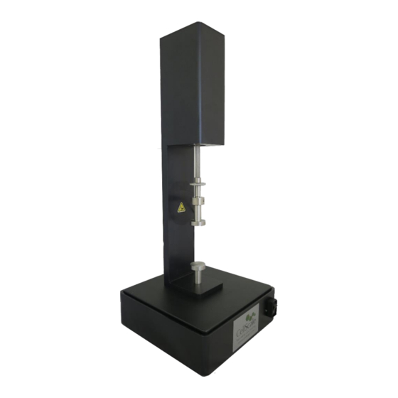
UniVert User Manual 1. General Information The UniVert is a precision test instrument designed for the compressive and tensile testing and analysis of materials including metals, polymers, and biological specimens. The system includes a test station and an integrated software interface to run and analyze test results. -
Page 7: Safety Warnings
This equipment must not be disassembled by the user or modified in any way. Manual Operating Controls There is a single power switch on the front of the control unit to turn on the UniVert. General Maintenance Clean the system as needed with mild soap and water or alcohol based cleaning solutions. -
Page 8: Testing Terminology
UniVert User Manual 2. Testing Terminology The UniVert is designed to apply uniaxial compressive and tensile forces to a variety of materials. This includes metals, plastics, and composites as well as biological materials. Multiphase Test Cycles In order to properly characterize and test a specimen, it is often necessary to load it to different degrees and at different rates. -
Page 9: Phases, Cycles, And Test Sequences
UniVert User Manual Phases, Cycles, and Test Sequences As the following diagram demonstrates, each application and release of load on the specimen is called a test cycle. The same test cycle can be repeated multiple times to achieve a certain goal (preconditioning, physiological conditioning, or testing);... -
Page 10: Test Phases: The Smallest Unit Of Testing
UniVert stretches or compresses the specimen until the predefined displacement is achieved. The force required to achieve the displacement is an output of the test. Under force control, the force applied to the specimen is predefined. The UniVert stretches or compresses the specimen until the predefined force is achieved. The displacement required to achieve the force is an output of the test. -
Page 11: Test Modes
UniVert User Manual Under force control: The step function achieves and maintains the desired force as quickly as possible. The amount of time it takes to achieve the desired force depends on the material being tested and the force control settings. -
Page 12: Software Overview
UniVert User Manual 3. Software Overview The software included with the UniVert device is called UniVert. It is divided into two modules, a data collection module and a review and analysis module. The data collection module is used to set test parameters, enable specimen loading and testing, and monitor test progress. The screen... -
Page 13: Output Files And Data Structures
UniVert User Manual Output Files and Data Structures For each test, the UniVert creates and saves three file types. The following table describes the three file types for a project named “Sample1”. Output from this test would be found in a “Sample1”... -
Page 14: Setting Up & Starting A Test
In the Create Test From Template dialog, perform the following steps: 1. Select a template that matches the type of test you wish to perform. See the UniVert Tip on how to select and use a template. You can modify the template parameters in Step 4, below. -
Page 15: Step 2: Reset The Actuator
By resetting the actuator, you are ensuring that the displacement measurements taken by the UniVert are accurate. To reset the actuator, select Reset Actuator from the Tools menu, or press on the toolbar. -
Page 16: Step 3: Specify Test Type
UniVert User Manual Step 3: Specify Test Type Access Test Mode in the Settings menu to select the appropriate test mode and install the platens, grips, or 3-point bend attachments (see Appendix D for this procedure). Step 4: Move the Actuator to a Specified Size After the actuator has been reset, it will remain in the fully retracted position and must be moved to a specified (reference or starting) position. -
Page 17: Step 5: Zero The Load Cell (Occasionally)
UniVert User Manual Step 5: Zero the Load Cell (occasionally) While it is not necessary to zero the load cell with every test sequence, we suggest zeroing the load cell at the start of a new test session. With repeated use, the zero point of the load cell can drift. - Page 18 Image Output Frequency Typically set to 1Hz for cycles > 5 seconds and 15 Hz for cycles < 5 seconds. UniVert Tip: Idle Current Idle current (holding current) can be applied to the motors. The motors have a holding force in the de-energized state of approximately 100N. If forces in excess of 100N are expected it is recommended that idle current is used to prevent position loss during velocity and direction changes when the motors are de-energized for a very short time.
-
Page 19: Step 7: Mounting A Specimen
Alternately, the Move Actuator to Specified Size command may be used. UniVert Tip: Compression Specimen Mounting Make sure to center the specimen on the platen as much as possible to ensure accuracy in the force reading. Ideally, specimens will have two parallel flat sides and will make full contact with both platens. -
Page 20: Grip Mounted Specimens
UniVert User Manual Grip Mounted Specimens Low Force Grips 1. Select an appropriate riser to accommodate the size of the specimen (See Appendix D). 2. Select a spring with an appropriate clamping force for the specimen being tested (see Appendix G for more details). - Page 21 UniVert User Manual High Force Grips 1. Select an appropriate riser to accommodate the size of the specimen (See Appendix 2. Select a spring with an appropriate clamping force for the specimen being tested (see Appendix G for more details).
-
Page 22: 3-Point Bend Specimens
UniVert User Manual 3-Point Bend Specimens 1. Use the 80mm riser to ensure the sample is in the range of the actuator (see Appendix 2. Choose the appropriate 3-Point Bend dowel for the type of test you wish to perform. -
Page 23: Step 8: Execute The Test
At the end of the completed test (both normally or prematurely terminated) the actuators will maintain their current position. UniVert Tip: Specimen Thickness Measuring the specimen thickness before and/or after a test is performed will allow stress calculations to be made from your output data. -
Page 24: Additional Settings
UniVert User Manual 5. Additional Settings Configuring Output Data Files From the Settings menu, select Data Output to display the dialogue shown on the left. Click the Configure button to select which of the following columns to output. → Output Column... -
Page 25: Advanced System Settings Dialogue
The degree of non-linearity increases with increasing strain. The UniVert approximates this non-linear curve with a series of linear segments. Typically, 10 line segments is a sufficiently close approximation. - Page 26 Tools menu select Move Actuators to Specified Load. The dialogue shown on the right will appear. The UniVert will attempt to achieve the specified load (force) but will stop when the specified load is reached, the...
-
Page 27: Range Limits
UniVert User Manual Range Limits Range limits can be accessed by selecting Range Limits from the Settings menu. Soft Limits To avoid collisions or sample destruction, it is useful to assign reasonable travel limits to the actuators. This is especially... -
Page 28: Configuring The Live Charting Graphs
UniVert User Manual Configuring the Live Charting Graphs The three graphs on the right side of the screen provide real-time user feedback during a test. These graphs are intended to be used for qualitative feedback, not for detailed analysis. The graphs are updated at a maximum frequency of 10Hz;... - Page 29 UniVert User Manual Graph Data Force versus Time This graph shows how the measured forces are changing with time. Peak loads per cycle and force relaxation are all easily seen in this type of graph. Force is proportional to nominal (engineering) stress.
-
Page 30: Reviewing Test Results
Tracking Data Overlay The basic UniVert system comes with a Logitech HD 1080p webcam intended to be used for recording images for image playback and review. This camera and software associated with it does not support image tracking. For image tracking to be available, the advanced scientific monochrome camera must be... -
Page 31: Selecting Images
UniVert User Manual Selecting Images The Images are shown in a tree structure on the top left panel. The tree structure organizes the images by: Set (line on the test parameter window) Cycle (iteration of a given Set) Phase (Preload/Stretch/Hold/Recovery/Rest phase of each... -
Page 32: Image Tracking: Overview
UniVert User Manual Image Tracking: Overview Image tracking is a function that can be used to quantify the motions of image features (specimen texture and fiducial markers). This can be useful for studying localized specimen deformations, verifying strain magnitudes, and comparing the results of one test to another. - Page 33 UniVert User Manual...
- Page 34 UniVert User Manual 6. Modify search parameters: Source The optimal source template is difficult to predict, but in general it is advantageous for the template to be large enough that it contains at Template least one feature, but not so large that it contains multiple features.
-
Page 35: Image Tracking: The Points Display Option
UniVert User Manual Image Tracking: The Points Display Option The Points option displays the points in their current location (i.e. their location on the currently displayed image) with or without gridline connecting points that were generated using the grid function. -
Page 36: Image Tracking: The Displacement Option
UniVert User Manual Image Tracking: The Displacement Option The Displacement Option displays the points in their current location as well as graphically representing their motion through time. Clicking the Details icon brings up the window shown to the right. This dialogue allows the user to change the reference image, change the type of connecting line, and change the line appearance. -
Page 37: Image Tracking: The Strains Option
UniVert User Manual Image Tracking: The Strains Option The Strains Option can only be used in conjunction with a grid of points (as opposed to individually placed points). This option calculates the regional strains inside every grid box and displays this data as an ellipse. One can imagine this is what would happen to a grid of circles drawn on the surface of the specimen at the beginning of the test. -
Page 38: Data Overlay
UniVert User Manual Data Overlay Data associated with each image is displayed below the tracking controls on the left side of the main window. Checking the Show Graph box displays this data as a graph overlaid on the images Clicking the details icon displays the window shown to the right. -
Page 39: Exporting Tracked Data
UniVert User Manual Exporting Tracked Data Tracked grid point coordinates and calculated grid strains can be exported to a .csv file. From the Export menu, select Data Points to display the dialogue shown on the right. The image list is automatically set to the currently selected images in the test image list tree. -
Page 40: Exporting Images And Movies
UniVert User Manual Exporting Images and Movies The current Image view, including all displayed tracking grids, tracking data and overlaid data can be exported as a metafile by selecting Current Image from the Export menu. Alternately, the current image view can be copied to the clipboard by pressing Ctrl-C on the keyboard. -
Page 41: System Hardware Settings
Settings menu, which brings up the window shown to the right. Camera The UniVert software can be equipped with the standard webcam package, the scientific camera package, or no camera at all. The software will automatically detect which camera configuration is in use. -
Page 42: Load Cell
UniVert User Manual Scientific Camera Package The advanced scientific camera package is not included with the base UniVert system and is available as an added feature. This advanced option provides high quality monochrome images suitable for image tracking and the associated software is enabled with the image tracking feature (See Section 6: Image Tracking). -
Page 43: Actuator And Motor
UniVert User Manual Actuator and Motor The actuator is driven by a stepper motor under open loop control. The motor moves a lead screw-driven shaft attached to the load cell and then the platens or grips. The actuator has a peak velocity of 20mm/s. To... - Page 44 UniVert User Manual Caution: Avoid touching the chamber back panel when the heater is on, it can become very hot! UniVert Tip: Preheat Fluid You can add preheated fluid to the fluid chamber to reduce warm up time.
-
Page 45: System Calibration And Advanced Tools
UniVert User Manual 8. System Calibration and Advanced Tools Load Cell Calibration The load cells are preset with a calibration factor at the production facility. However, calibration in the field is recommended. When the load cells are set up for the first time, changed, or moved it is advisable to perform a load cell calibration. - Page 46 UniVert User Manual 5. Zero the load cell to remove the weight of the platen from the calibration values measured 6. Measure the zero load condition for the first calibration point (no calibration weight) a. Enter “0” in the Enter Weight dialogue b.
- Page 47 UniVert User Manual Note: Only take one reading per calibration weight used. Multiple readings of a single load value can cause an error in the calibration algorithm Be sure to re-zero the load cell in the upright testing position...
-
Page 48: Alternate Method
Alternate Method When calibrating load cells with large full scale values (100N, 200N) the calibration weight required may not fit inside the UniVert main unit when it is placed upside down. In this case, follow these steps: 1. Carefully remove the load cell being calibrated. - Page 49 UniVert User Manual 3. Orient the setup such that the measuring end of the load cell is facing up and continue with the standard calibration procedure described above. System Alert: Load Cell Handling It is important to handle load cells carefully. Here are some things to consider while handling a load cell: •...
-
Page 50: Zero Position Calibration
An actuator zero position is preset at the production facility before the UniVert unit is shipped. However, the zero position should be re-calibrated on initial system setup and whenever the grips, platens, load cells, or risers are changed. - Page 51 To calibrate the zero position, follow these steps: 1. Before starting a center position calibration, choose an appropriate calibration spring (provided with the UniVert system). Use the bronze calibration spring with the 80mm riser, the red calibration spring with the 40mm riser, and the blue calibration spring when no riser is used.
- Page 52 UniVert User Manual 3. Place the provided calibration spring on the bottom platen or grip. 4. Zero the load cell using the Zero Load Cells button 5. Specify the spring length (mm). This figure is provided for each spring included in the UniVert system.
-
Page 53: System Stiffness Compensation
(see Section 5). UniVert Tip: When to Apply System Stiffness Compensation Typically, System Stiffness Compensation will not be required. It may be useful, however, when testing stiff specimens that achieve high loads at low displacements. - Page 54 Before starting the software utility, attach the 80 mm riser and compression platens to the UniVert system. Also, place the Stiffness Compensation spacer that is provided (a small washer) onto the exact center of the lower platen.
- Page 55 UniVert User Manual To perform system stiffness compensation calibration, follow these steps: 1. Open the System Stiffness Compensation utility by selecting Advanced → System Compensation from the Tools menu. 2. Zero the load cells. 3. Use the jog buttons to decrease the gap above the spacer.
-
Page 56: Snap Image Feature
Update Firmware Periodic firmware updates may be issued by CellScale for the UniVert. 1. With the UniVert connected to the PC and turned on, launch the firmware update software located in the Windows start menu under UniVert>Utilities. 2. Load the firmware file using the Load Update File button. -
Page 57: Troubleshooting
The supply power surges or is interrupted. When a communication error occurs, close UniVert software, check connections, power cycle the UniVert Device, and restart the UniVert software. Be sure to reset the actuators before setting up a new test. UniVert Tip: Preventing Power Disruptions We recommend plugging the UniVert (and host computer) into an uninterruptable power supply (UPS) or battery back-up. -
Page 58: Actuator Limits
Moving the actuator out of range with Move to Size The UniVert software will not allow actuators to be moved to a size outside of the actuator range limit. An error message will warn the user of the invalid position and display the minimum... - Page 59 Moving the actuator out of range with Move to Force If the actuator is moved past the range limit when using Move to Force the UniVert software will display an error message (shown below). It is recommended to perform an actuator reset before...
- Page 60 UniVert User Manual Reaching the actuator limit during a test: If the actuator is moved past the range limit during a test, the UniVert software will terminate the test and display an error message: UniVert Tip: Zero Position Calibration Perform a zero position calibration (see Section 8) when the load cell, grips, or risers are changed.
-
Page 61: Appendix A: Unpacking And Initial Setup
UniVert User Manual Appendix A: Unpacking and Initial Setup The UniVert has been packed securely to protect it during shipping. In addition, system accessories have been packed in a separate box. The system components listed below may be unpacked and laid out before system setup. A space 30cm x 30cm with 50cm overhead clearance is required for setup. - Page 62 UniVert User Manual Step 1: Unpack all components and have them ready for assembly.
- Page 63 UniVert User Manual Step 2: Attach the base plate to the main unit (4 x M3x8 fasteners)
- Page 64 UniVert User Manual Step 3: Set the UniVert main unit on the control box and connect the actuator cable to the main unit.
- Page 65 UniVert User Manual Step 4: Install the UniVert software. See Appendix C: Software Installation for more information. Step 5: Attach the load cell. See Appendix B: Load Cell Installation for this procedure. Step 6: Attach platens, grips, or 3-point bending components to...
- Page 66 A 24V brick power supply powers the UniVert system via a barrel connector on the back of the control box. The UniVert control box is connected to the PC via a USB connection.
- Page 67 Step 8: Launch the software and begin a test to ensure the UniVert loads up normally. Run UniVert.exe and start a new test (File > Collect New). The software will output information on the initialization of the camera, load cell, and actuator. The software will output System Ready! when all systems have loaded and the UniVert is ready for testing.
-
Page 68: Appendix B: Load Cell Installation
UniVert User Manual Appendix B: Load Cell Installation In order to avoid load cell damage, proper installation is required. Follow these steps when changing load cells or installing for the first time: 1. Identify the active end of the load cell (see below image). This is the MEASURING END of the load cell which results in a force reading. - Page 69 UniVert User Manual 3. Screw the load cell/thumbnut combination onto the actuator. At this point the measuring end of the load cell should be facing down, and the non-measuring end attached to the thumbnut and actuator. An M6 locking disc may be used between the thumbnut and actuator so the rotational...
-
Page 70: Appendix C: Software Installation
A Windows based PC (Windows 7 or above) with at least 2 USB ports is required to operate the UniVert. A label on the cover of the manual contains a web address to download the UniVert software installation package. These files contain the software installer for the user interface and control software for the UniVert. - Page 71 UniVert User Manual...
- Page 72 UniVert User Manual...
- Page 73 UniVert User Manual...
- Page 74 UniVert User Manual...
- Page 75 UniVert User Manual...
-
Page 76: Appendix D: Test Setup
Choosing and Installing a Riser for the Bottom Grip, Platen, or 3 Point Bend Block 40mm and 80mm risers are included with the UniVert system. These are placed between the bottom of the main unit and the lower platen, grip, or 3-point bending block. The risers are used to set the available specimen size for testing. - Page 77 UniVert User Manual...
-
Page 78: Tension Test Setup
UniVert User Manual 4. Continue with a test setup procedure using the grips, platens, or 3-point bend blocks. This is outlined below. Tension Test Setup 1. Set the test mode to Tension (Settings>Test Mode>Tension). This setting is specific to the test template being used and can be saved to a template. - Page 79 UniVert User Manual 4. Screw the appropriate grip onto the measuring end of the load cell after the locking disc. Tightening the locking disc against the grip allows the grip to be secured to the actuator at any rotational position.
- Page 80 UniVert User Manual 6. Align the two grips until they are parallel. A Zero Position Calibration is required after changing grips or platens. See Section 8 of this manual for more details.
-
Page 81: Compression Test Setup
UniVert User Manual Compression Test Setup 1. Set the test mode to compression (Settings>Test Mode>Compression). This setting is specific to the test template being used and can be saved to a template. 2. Install the desired load cell (see Appendix B) 3. - Page 82 UniVert User Manual 4. Choose an appropriate riser and attach the bottom platen. Use an M5x16 fastener for a test setup with NO riser, a M5x60 fastener for a 40mm riser, and an M5x100 fastener for the 80mm riser. 5. A Zero Position Calibration is required after changing grips or platens. See Section 8 of...
-
Page 83: 3-Point Bend Test Setup
UniVert User Manual 3-Point Bend Test Setup 1. Set the test mode to compression (Settings>Test Mode>Compression). 2. Install the desired load cell (see Appendix B) 3. Attach a locking disc to the measuring end of the load cell. - Page 84 UniVert User Manual 4. Assemble the 3-Point Bending Block and sliders using M2x6 fasteners, 4-40 - 5/16” fasteners, large O-Rings and small O-Rings as illustrated below (Note: Choose a dowel size appropriate for the test being performed). 5. Screw the bending block onto the measuring end of the load cell and tighten in the correct position using the locking disc.
- Page 85 UniVert User Manual Attach and align the 3-Point bend rail onto the bottom of the motor housing using an M5x100 fastener and 80mm riser. 7. Secure both sliders onto the rail in the desired position by tightening the fasteners.
-
Page 86: Appendix E: Camera Setup
UniVert User Manual Appendix E: Camera Setup Webcam The webcam included with the UniVert system is used for recording images at up to 5Hz. The UniVert will function with or without the camera plugged in. To setup the camera, follow these steps: 1. - Page 87 UniVert User Manual 3. Set the camera in the desired recording position using the flexible tripod. 4. Refer to Section 7: System Hardware Settings for additional camera settings.
-
Page 88: Scientific Camera
UniVert User Manual Scientific Camera The scientific camera, an optional add-on to the UniVert system, is used for recording images at up to 15Hz and is compatible with the image tracking feature of the software. To setup the camera, follow these steps: 1. - Page 89 UniVert User Manual 4. Place the ringlight on the end of the lens. Lock it in place using the thumb screws. Brightness level can be controlled by the dial on the power supply. Bring the camera to the desired height by adjusting the separation of the tripod legs. Note...
- Page 90 UniVert User Manual 6. The image brightness can be adjusted using the Iris Ring on the lens. It is recommended to leave the Iris Ring fully open and control image brightness with the ringlight and the Hardware Settings in the Iris Ring software (see Section 7).
-
Page 91: Appendix F: Media Bath Setup
Note: The load cell and appropriate grip or platen should already be attached before completing these steps. 1. Place the polycarbonate media chamber on the UniVert base. 2. Fit a ½” O-ring supplied with the system into the groove in the bottom of the media chamber. - Page 92 UniVert User Manual 6. Thread the chosen fastener through the bottom of the base plate, slide the corresponding riser on top, and tighten the appropriate grip or platen to the fastener. 7. Make sure the O-ring on the back edge of the chamber is properly set, lower the...
- Page 93 UniVert User Manual 8. Place the UniVert motor housing back to its upright position and attach all connections for heater and temperature sensor. 9. Secure the temperature sensor to the top of the chamber using an M4x8 Flat head fastener and the supplied D-clip...
- Page 94 UniVert User Manual 10. MAKE SURE THE VALVE IS CLOSED BEFORE FILLING THE CHAMBER WITH FLUID...
- Page 95 UniVert User Manual 11. To activate the fluid chamber heater, the unit must be powered on and the heater cable must be connected (the computer and software do not need to be on yet). At this point, the heater will warm the fluid to the last used temperature set point. The temperature set point can be changed by selecting Hardware from the Settings menu.
-
Page 96: Appendix G: Changing Grip Springs
10N, 20N, and 40N of gripping force, respectively. Note: This section describes how to change grip springs on the updated UniVert grips. If you have the previous version of UniVert grips, please see Appendix H for instructions on how to change grips springs. - Page 97 UniVert User Manual 3. Use a screwdriver to push the dowel out of the grip. 4. Carefully take the grip halves and spring out of the jig. It may be easier to use two hands for this step. Use one hand to squeeze the grip and the other to palm over the assembly to contain all the parts as it is removed from the jig.
- Page 98 UniVert User Manual 7. Align the clamping face of the bottom half of the grip to the top and carefully press it down to compress the spring. 8. Place the grip and new spring into the jig. Again, using two hands may make this step easier.
- Page 99 UniVert User Manual 9. Press the dowel into the grip 10. Remove the grip from the jig...
-
Page 100: Appendix H: Changing Grip Springs (Legacy Grips)
The grips used for tension testing come in three different gripping strengths to suit different materials and tests. Replacement springs of varying stiffness are provided with the UniVert and these may be switched at any time using the hook tool provided. The light, medium and heavy springs will provide 1.5N, 6N, and 15N of gripping force respectively. - Page 101 3. Secure one side of the spring onto the grip with a metal dowel. 4. With one hand use the hook tool to pull the other side of the spring into place and secure with another metal dowel (Note: This step may be easier with two people) © Copyright 2020 CellScale Biomaterials Testing.
Need help?
Do you have a question about the UniVert and is the answer not in the manual?
Questions and answers