Delta Modulon DPH Series User Manual
Hide thumbs
Also See for Modulon DPH Series:
- User manual (268 pages) ,
- User manual (148 pages) ,
- User manual (232 pages)

Subscribe to Our Youtube Channel
Related Manuals for Delta Modulon DPH Series


Summary of Contents for Delta Modulon DPH Series
- Page 1 The power behind competitiveness Delta UPS - Modulon Family DPH Series, Three Phase 20-80 kVA/ 20-120 kVA User Manual www.deltapowersolutions.com...
- Page 2 Copyright © 2020 by Delta Electronics Inc. All Rights Reserved. All rights of this User Manual (“Manual”), including but not limited to the contents, information, and figures are solely owned and reserved by Delta Electronics Inc.
-
Page 3: Table Of Contents
Table of Contents Table of Contents Important Safety Instructions ---------------------------------------------- 1-1 Installation Warnings ---------------------------------------------------------------------- 1-2 Connection Warnings --------------------------------------------------------------------- 1-2 Usage Warnings --------------------------------------------------------------------------- 1-4 Storage Warnings ------------------------------------------------------------------------- 1-5 Standard Compliance -------------------------------------------------------------------- 1-6 Introduction ---------------------------------------------------------------------- 2-1 General Overview ------------------------------------------------------------------------- 2-2 Package Inspection ----------------------------------------------------------------------- 2-2 Functions &... - Page 4 Communication Interfaces at the Rear of the Touch Panel --------------------4-17 Installation and Wiring ------------------------------------------------------- 5-1 Before Installation and Wiring ---------------------------------------------------------- 5-2 Installation Environment ----------------------------------------------------------------- 5-2 UPS Transportation ---------------------------------------------------------------------- 5-4 Fixing the UPS ----------------------------------------------------------------------------- 5-5 Wiring ----------------------------------------------------------------------------------------- 5-7 5.5.1 Pre-wiring Warnings ------------------------------------------------------------ 5-7 --------------------------------------5-10 Modulon DPH Series...
- Page 5 Table of Contents 5.5.3 Single Unit Wiring --------------------------------------------------------------5-12 5.5.4 Parallel Unit Wiring ------------------------------------------------------------5-18 External Battery Cabinet Connection Warnings ----------------------------------5-22 STS Module --------------------------------------------------------------------------------5-29 5.7.1 STS Module Installation ------------------------------------------------------5-30 5.7.2 STS Module Removal --------------------------------------------------------5-32 5.7.3 STS Module’s LED Indicator ------------------------------------------------5-34 Power Module (Optional) ---------------------------------------------------------------5-35 5.8.1 Power Module Installation ---------------------------------------------------5-36 5.8.2...
- Page 6 7.11.2 Historical Event -----------------------------------------------------------------7-60 7.11.3 Statistics --------------------------------------------------------------------------7-62 7.11.4 Test --------------------------------------------------------------------------------7-62 7.11.5 Clear -------------------------------------------------------------------------------7-63 7.11.6 Advanced Diagnosis ----------------------------------------------------------7-64 7.11.7 Version & S/N -------------------------------------------------------------------7-65 Optional Accessories --------------------------------------------------------- 8-1 Maintenance ---------------------------------------------------------------------- 9-1 --------------------------------------- A1-1 Appendix 2 : Warranty ------------------------------------------------------------- A2-1 Modulon DPH Series...
-
Page 7: Important Safety Instructions
Important Safety Instructions Important Safety Instructions 1.1 Installation Warnings 1.2 Connection Warnings 1.3 Usage Warnings 1.4 Storage Warnings 1.5 Standard Compliance... -
Page 8: Installation Warnings
Leave adequate space around all sides of the UPS for proper ventilation and mainte- nance. Please refer to 5.2 Installation Environment. Only authorized Delta engineers or service personnel can perform installation and maintenance. If you want to install the UPS by yourself, please install it under the su- pervision of authorized Delta engineers or service personnel Follow the IEC 60364-4-42 standard to install the UPS. - Page 9 Important Safety Instructions 3. Each protective device could be (1) a breaker, (2) a switch connected in series with fuses, or (3) a switch* . For the protective device’s rating current, please refer to the table below. 20kVA 40kVA 60kVA 80kVA 100kVA 120kVA...
-
Page 10: Usage Warnings
(that have serious surge current) to the UPS, it needs to be de-rated according to on-site applications. For such special applications, please contact Delta service personnel for the accurate UPS sizing. The UPS is not suitable for connecting with any asymmetrical loads. -
Page 11: Storage Warnings
5. Disconnect the charging source prior to connecting or disconnecting the batteries’ terminals. You must contact Delta customer service if either of the following events occurs: 1. Liquid is poured or splashed on the UPS. 2. The UPS is deformed. -
Page 12: Standard Compliance
Standard Compliance EN 62040-1 EN 61000-6-4 EN 62040-2 Category C3 EN 61000-4-2 EN 61000-4-3 EN 61000-4-4 EN 61000-4-5 EN 61000-4-6 EN 61000-4-8 EN 61000-2-2 Modulon DPH Series... -
Page 13: Introduction
Introduction Introduction General Overview Package Inspection Functions & Features Exterior and Dimensions Front View Internal View Rear View Tri-color LED Indicator & Buzzer... -
Page 14: General Overview
1. Check the rating label attached to the UPS and make sure the device No. and capacity match what you ordered. 2. Examine if any parts are loose or damaged. 3. The UPS package contains the following items. Please check if any items are missing. × 18 × 2 × 2 Modulon DPH Series... -
Page 15: Functions & Features
Introduction Item Q'ty 1 PC User Manual 1 PC RS-232 Cable (1.8 meters (5.91 ft)) 1 PC Parallel Cable (3 meters (9.84 ft)) 1 PC Test Report 1 PC 1 PC (two copies placed inside the UPS cabinet) M10 Screw (used for input/ output/ battery/ 18 PCS grounding wiring) USB Cable... - Page 16 AC start-up function even when the UPS is not connected to the batteries. WARNING: Please note that when the UPS is not connected to the batteries, it will not protect your equipment if the utility power is lost. Modulon DPH Series...
-
Page 17: Exterior And Dimensions
Introduction Connects at maximum eight external battery cabinets to extend backup time. Sets up schedulable battery test and battery replacement alarm. Battery temperature monitoring and compensation. Optional battery management system (BMS) allows measurement of every battery’s voltage. Smart battery charger design allows auto-charging or manual charging to shorten charging time. -
Page 18: Front View
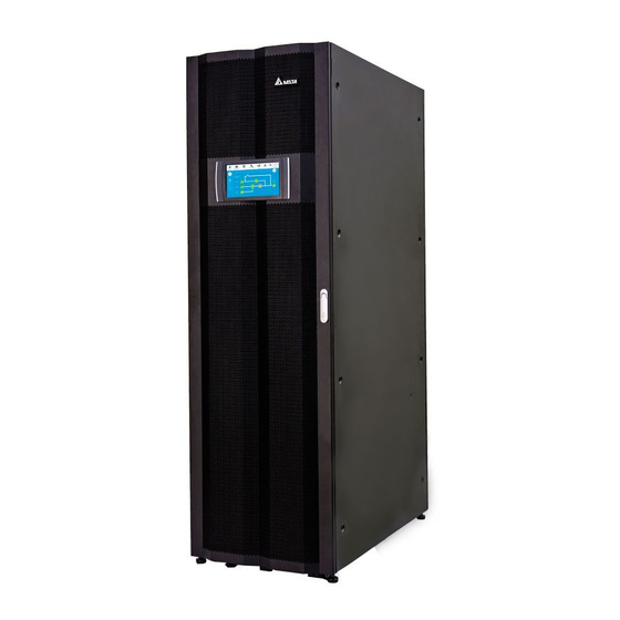
On the front of the UPS, there are a 10” color touch panel, a tri-color LED indicator, a door switch, four casters and four leveling feet. Please see Figure 2-2. 10” Color Touch Panel Tri-color LED Indictor Door Switch Levelling Foot Levelling Feet Casters (Figure 2-2: UPS Front View) Modulon DPH Series... -
Page 19: Internal View
(Figure 2-3: How to Open the UPS Front Door) Internal View WARNING: Only authorized Delta engineers or service personnel can perform installation, wiring, panel & cover removal, maintenance and operation. If you want to execute any action mentioned above by yourself, the action must be under the supervision of authorized Delta engineers or service personnel. - Page 20 2. The Bottom Three Slots Don’t Have Covers. STS Module Input, Bypass, Manual Bypass & OUTPUT INPUT BYPASS MANUAL BYPASS BREAKER BREAKER BREAKER BREAKER Output Breakers (from Left to Right) Wiring Terminal Cover (Figure 2-4: UPS Internal View with front Door Open) Modulon DPH Series...
- Page 21 Introduction Description The communication interfaces are located at two areas, (1) on the front of the UPS with front door open and (2) at the rear of the touch panel. For relevant information, please refer to 4. Communication Interfaces. 1. For 20 ~ 80kVA UPS, there are four power module slots. The top two slots have covers but the bottom two do not.
- Page 22 (Figure 2-9: Wiring Terminals_ UPS Output) Internal View (with Front Door Open & Wiring Terminal Cover Removal) INPUT BYPASS MANUAL BYPASS OUTPUT BREAKER BREAKER BREAKER BREAKER AC INPUT BYPASS INPUT UPS OUTPUT Grounding Terminals & (Figure 2-10: Wiring Terminals_ Grounding) Modulon DPH Series 2-10...
-
Page 23: Rear View
Introduction Rear View WARNING: Only authorized Delta engineers or service personnel can perform installation, wiring, panel & cover removal, maintenance and operation. If you want to execute any action mentioned above by yourself, the action must be under the supervision of authorized Delta engineers or service personnel. -
Page 24: Tri-Color Led Indicator & Buzzer
INPU T BRE AKE BYPA SS BRE AKE MAN UAL BYPA SS BRE AKE OUT PUT BRE AKER (Figure 2-13: Buzzer Location) Table 2-1 outlines the status of the tri-color LED indicator, UPS operation mode, and buzzer. Modulon DPH Series 2-12... - Page 25 Introduction Table 2-1: Tri-color LED Indicator, UPS Operation Mode & Buzzer Tri-color LED Status Meaning Indicator Indicates the UPS’s current operation mode; for its corresponding text shown in the upper right corner of the LCD screen, please refer to the following table. UPS Operation Text on the LCD Screen Mode...
-
Page 27: Operation Modes
Operation Modes Operation Modes 3.1 Single Input 3.2 Dual Input 3.3 Hot Standby Redundancy (Only For Dual Input & At Least Two UPSs) 3.4 Common Battery (Only for Parallel UPSs connecting to the Same External Battery Cabinet(s)) -
Page 28: Single Input
After receiving the DC power, the inverter converts it into clean and stable AC power to the connected critical loads via the Output Breaker (Q4). Please refer to Figure 3-1. During On- Line mode, the UPS’s tri-color LED illuminates green and the text 'On-Line' appears in the upper right corner of the screen. Modulon DPH Series... -
Page 29: Battery Mode_ Single Input_ Single Unit
Operation Modes Static Switch Rectifier Inverter MAIN LOAD Batteries (Figure 3-1: On-Line Mode Diagram_ Single Input Single Unit) 3.1.2 Battery Mode_ Single Input_ Single Unit The UPS transfers to Battery mode automatically if the main AC source is abnormal, for example, when unstable voltage or a power outage occurs. -
Page 30: Bypass Mode_ Single Input_ Single Unit
(see Figure 5-8~Figure 5-11 for the location of these terminal blocks and terminals) and any copper bars connected to the Manual Bypass Breaker (Q3), as they may carry high voltage. the connected critical loads are not protected. Modulon DPH Series... - Page 31 Operation Modes When the UPS needs maintenance, you can manually switch the UPS to Manual Bypass mode. To let the UPS run in Manual Bypass mode, please follow the procedures below: Tap the LCD’s ON/ OFF Button ( ) and the 'POWER OFF?' screen will pop up to 'YES'.
-
Page 32: Eco Mode_ Single Input_ Single Unit
For the diagram of Frequency Conversion mode, please see Figure 3-6. During Frequency Conversion mode, the UPS’s tri-color LED illuminates green and the text 'Frequency Conversion' appears in the upper right corner of the screen. Modulon DPH Series... -
Page 33: Green Mode_ Single Input_ Single Unit
Operation Modes Static Switch Rectifier Inverter MAIN LOAD Batteries (Figure 3-6: Frequency Conversion Mode Diagram_ Single Input Single Unit) 3.1.7 Green Mode_ Single Input_ Single Unit To activate Green mode, please refer to 6.2.7 Green Mode Start-up Procedures, 7.6 Main Screen and 7.10.2 Mode Setting. -
Page 34: Energy Recycle Mode_ Single Input_ Single Unit
UPS’s tri-color LED illuminates yellow and the text 'Energy Recycle' appears in the upper right corner of the screen. Static Switch Rectifier Inverter MAIN LOAD Batteries (Figure 3-8: Energy Recycle Mode Diagram_ Single Input Single Unit) Modulon DPH Series... -
Page 35: On-Line Mode_ Single Input_ Parallel Units
Operation Modes 3.1.9 On-Line Mode_ Single Input_ Parallel Units In On-Line mode (parallel), the total loads will be equally shared by parallel UPSs. If one of the parallel units fails and its load is less than the total capacity of the remaining parallel units, the failing UPS's output will be switched off and its load will be equally shared by the remaining parallel units. -
Page 36: Battery Mode_ Single Input_ Parallel Units
'Battery' in the upper right corner. Please refer to Figure 3-10 for the path of electrical power through the parallel UPSs in Battery mode. Static Switch Rectifier Inverter MAIN Batteries LOAD Static Switch Rectifier Inverter MAIN Batteries (Figure 3-10: Battery Mode Diagram_ Single Input Parallel Units) Modulon DPH Series 3-10... -
Page 37: Bypass Mode_ Single Input_ Parallel Units
Operation Modes 3.1.11 Bypass Mode_ Single Input_ Parallel Units In Bypass mode (parallel), when all inverters encounter abnormal situations such as overload, short circuit, abnormal output voltage or low battery, they will automatically shut themselves down. Meanwhile, if all parallel UPSs detect the bypass AC source is normal, they will automatically switch to Bypass mode to protect the connected critical loads from power interruption. -
Page 38: Manual Bypass Mode_ Single Input_ Parallel Units
Power of the connected critical loads will be supplied by manual bypass. During Manual Bypass mode (parallel), all parallel Figure 3-12 for the path of electrical power through the parallel UPSs in Manual Bypass mode. Modulon DPH Series 3-12... - Page 39 Operation Modes Static Switch Rectifier Inverter MAIN Batteries LOAD Static Switch Rectifier Inverter MAIN Batteries (Figure 3-12: Manual Bypass Mode Diagram_ Single Input Parallel Units) 3-13...
-
Page 40: Eco Mode_ Single Input_ Parallel Units
'ECO' in the upper right corner. Please see Figure 3-13 for the path of electrical power through the parallel UPSs in ECO mode. Static Switch Rectifier Inverter MAIN Batteries LOAD Static Switch Rectifier Inverter MAIN Batteries (Figure 3-13: ECO Mode Diagram_ Single Input Parallel Units) Modulon DPH Series 3-14... -
Page 41: Green Mode_ Single Input_ Parallel Units
Operation Modes 3.1.14 Green Mode_ Single Input_ Parallel Units To activate Green mode, please refer to 6.2.7 Green Mode Start-up Procedures, 7.6 Main Screen and 7.10.2 Mode Setting. that each parallel UPS’s system will automatically detect its own output status (i.e. total load color LED illuminates green and each UPS’s LCD shows the text 'Green' in the upper right corner. -
Page 42: Dual Input
Output Breaker (Q4). During the conversion process, output voltage remains the same. Please see Figure 3-16 for Battery mode diagram. During Battery mode, the UPS’s tri-color LED illuminates yellow and the text 'Battery' appears in the upper right corner of the screen. Modulon DPH Series 3-16... -
Page 43: Bypass Mode_ Dual Input_ Single Unit
Operation Modes Static Switch BYPA. Rectifier Inverter MAIN LOAD Batteries (Figure 3-16: Battery Mode Diagram_ Dual Input Single Unit) 3.2.3 Bypass Mode_ Dual Input_ Single Unit When the inverter encounters abnormal situations such as over temperature, overload, short circuit, abnormal output voltage or low battery, it will automatically shut itself down. If the UPS detects the bypass AC source is normal, it will automatically switch to Bypass mode to protect the connected critical loads from power interruption. -
Page 44: Manual Bypass Mode_ Dual Input_ Single Unit
Turn OFF the Bypass Breaker (Q2). Turn OFF the Input Breaker (Q1) and Output Breaker (Q4). Turn OFF each external battery cabinet’s breaker (Q5). personnel can perform maintenance safely. Please see Figure 3-18 for Manual Bypass Modulon DPH Series 3-18... -
Page 45: Eco Mode_ Dual Input_ Single Unit
Operation Modes Static Switch BYPA. Rectifier Inverter MAIN LOAD Batteries (Figure 3-18: Manual Bypass Mode Diagram_ Dual Input Single Unit) 3.2.5 ECO Mode_ Dual Input_ Single Unit To activate ECO mode, please refer to 6.2.5 ECO Mode Start-up Procedures, 7.6 Main Screen and 7.10.2 Mode Setting. -
Page 46: Frequency Conversion Mode_ Dual Input_ Single Unit
Figure 3-20. During Frequency Conversion mode, the UPS’s tri-color LED illuminates green and the text 'Frequency Conversion' appears in the upper right corner of the screen. Static Switch BYPA. Rectifier Inverter MAIN LOAD Batteries (Figure 3-20: Frequency Conversion Mode Diagram_ Dual Input Single Unit) Modulon DPH Series 3-20... -
Page 47: Green Mode_ Dual Input_ Single Unit
Operation Modes 3.2.7 Green Mode_ Dual Input_ Single Unit To activate Green mode, please refer to 6.2.7 Green Mode Start-up Procedures, 7.6 Main Screen and 7.10.2 Mode Setting. Green mode is the same as On-Line mode, but the difference is that the system will the UPS. -
Page 48: On-Line Mode_ Dual Input_ Parallel Units
Figure 3-22 for the path of electrical power through the parallel UPSs in On-Line mode. Static Switch BYPA. Rectifier Inverter MAIN Batteries LOAD Static Switch BYPA. Rectifier Inverter MAIN Batteries (Figure 3-22: On-Line Mode Diagram_ Dual Input Parallel Units) Modulon DPH Series 3-22... -
Page 49: Battery Mode_ Dual Input_ Parallel Units
Operation Modes 3.2.9 Battery Mode_ Dual Input_ Parallel Units If the main AC source is abnormal, for example, when unstable voltage or a power outage occurs, all parallel UPSs will automatically transfer from On-Line mode to Battery mode. During the conversion process, output voltage remains the same. During Battery mode (parallel), each UPS’s tri-color LED illuminates yellow and each UPS’s LCD shows the text 'Battery' in the upper right corner. -
Page 50: Bypass Mode_ Dual Input_ Parallel Units
Please see Figure 3-24 for the path of electrical power through the parallel UPSs in Bypass mode. Static Switch BYPA. Rectifier Inverter MAIN Batteries LOAD Static Switch BYPA. Rectifier Inverter MAIN Batteries (Figure 3-24: Bypass Mode Diagram_ Dual Input Parallel Units) Modulon DPH Series 3-24... -
Page 51: Manual Bypass Mode_ Dual Input_ Parallel Units
Operation Modes 3.2.11 Manual Bypass Mode_ Dual Input_ Parallel Units WARNING: 1. In Manual Bypass mode, make sure that all of the breakers (except each UPS’s Manual Bypass Breaker (Q3)) are in the OFF position before working on any of the parallel UPSs’ internal circuits. This avoids electric shock. no high voltage inside all parallel UPSs and maintenance can be performed safely. - Page 52 Static Switch BYPA. Rectifier Inverter MAIN Batteries LOAD Static Switch BYPA. Rectifier Inverter MAIN Batteries (Figure 3-25: Manual Bypass Mode Diagram_ Dual Input Parallel Units) Modulon DPH Series 3-26...
-
Page 53: Eco Mode_ Dual Input_ Parallel Units
Operation Modes 3.2.12 ECO Mode_ Dual Input_ Parallel Units To activate ECO mode, please refer to 6.2.5 ECO Mode Start-up Procedures, 7.6 Main Screen and 7.10.2 Mode Setting. In ECO mode (parallel), when each parallel UPS’s bypass input voltage and frequency are within the setup range (default: voltage ±10% and frequency ±3Hz), each parallel UPS works in Bypass mode;... -
Page 54: Green Mode_ Dual Input_ Parallel Units
Please see Figure 3-27 for the path of electrical power through the parallel UPSs in Green mode. Static Switch BYPA. Rectifier Inverter MAIN Batteries LOAD Static Switch BYPA. Rectifier Inverter MAIN Batteries (Figure 3-27: Green Mode Diagram_ Dual Input Parallel Units) Modulon DPH Series 3-28... -
Page 55: Hot Standby Redundancy (Only For Dual Input & At Least Two Upss)
Operation Modes Hot Standby Redundancy (Only For Dual Input & At Least Two UPSs) have a hot standby redundancy function. If you use two UPSs and wish them to work in hot standby redundancy mode, please connect the output of UPS1 to the bypass input of UPS 2. Please see Figure 3-28. -
Page 56: Common Battery
2. * The item 'Equalized Charge Voltage' mentioned above will change into 'Restore Voltage' if you use the Delta lithium-ion batteries with the optional multifunctional communication card (MFC) being installed in the smart slot shown in Figure 4-15. For relevant information, please refer to 7.10.4 Battery &... - Page 57 Operation Modes Static Switch BYPA. Rectifier Inverter MAIN LOAD Static Switch BYPA. Batteries Rectifier Inverter MAIN (Figure 3-29: Common Battery Diagram_ only for Parallel UPSs Connecting to the Same External Battery Cabinet(s)) 3-31...
-
Page 59: Communication Interfaces
Communication Interfaces Communication Interfaces 4.1 Communication Interfaces on the Front of the UPS with Front Door Open 4.2 Communication Interfaces at the Rear of the Touch Panel... -
Page 60: Communication Interfaces On The Front Of The Ups With Front Door Open
START O/P DRY I/P DRY EXT. BATT EXT.SWITCH CONTACT CONTACT TEMP. STATUS BT1 BT2 REPO BATT. NC NO START BT3 BT4 PARALLEL RS-232 (Figure 4-2: Communication Interfaces_ on the Front of the UPS with Front Door Open) Modulon DPH Series... - Page 61 1. You can install the optional Relay I/O card in the SMART slot for dry contact expansion. 2. If you use the Delta lithium-ion batteries, you must purchase the optional multifunctional communication card (MFC) and install it in the SMART slot to monitor the status and...
-
Page 62: Display Port
4.1.1 Display Port Before shipment, the display port has been connected to the 10” touch panel with the designated cable in Delta factory. 4.1.2 REPO Dry Contacts The REPO dry contacts provide you with quick and convenient interfaces to shut down the UPS safely when an emergency occurs. -
Page 63: External Battery Temperature Dry Contacts
Communication Interfaces Jump CNR3 Dry Contact Card (Figure 4-6: Jump CNR3 Location) 4.1.3 External Battery Temperature Dry Contacts You can use the external battery temperature dry contacts (BT1, BT2, BT3 and BT4) to detect at maximum four external battery cabinets’ temperature. You need to purchase the battery cabinet temperature sensor cable (optional). -
Page 64: External Switch/ Breaker Status Dry Contacts
There are four sets of external switch/ breaker status dry contacts (S1, S2, S3 and S4), which can be used to respectively detect the status of input, bypass, output and manual bypass switches or breakers. To enable the functions of these dry contacts, please contact Delta customer service team. EXT.SWITCH STATUS... - Page 65 Communication Interfaces O/P DRY CONTACT DRY F_NO +12VS COMM_F DRY 6 DRY E_NO +12VS COMM_E DRY 5 DRY D_NO +12VS P6 (Max. 0.5A/12V) P5 (Max. 0.5A/12V) COMM_D P4 (Max. 0.5A/12V) DRY 4 DRY C_NO P3 (Max. 0.5A/12V) +12VS P2 (Max. 0.5A/12V) P1 (Max.
- Page 66 UPS will send a signal to the connected 20 Backfeed Protection external shunt trip device to cut off the backfeed voltage. When any UPS alarm occurs, the UPS will send an 21 General Alarm I/O signal. Modulon DPH Series...
-
Page 67: Input Dry Contacts
Communication Interfaces 4.1.6 Input Dry Contacts There are four sets of programmable input dry contacts (see Figure 4-10). The input dry contacts allow the UPS to receive external signals from peripheral devices and let the UPS response accordingly. Please use the touch panel to set each dry contact as normally open There are ten events that can be assigned according to your applications. -
Page 68: Parallel Communication Card
The battery fuse is blown. NOTE: If you use non-Delta lithium-ion batteries, you must set up and Charger Off (Negative) these two items. Please refer to 7.10.4 Battery & Charging Setting and 7.10.6 Dry Contact Setting to perform relevant setup. If you have any questions, please contact Delta customer service. -
Page 69: Parallel Ports
Communication Interfaces You can purchase the optional parallel communication card and install it into the parallel communication card slot. For the slot location, please refer to Figure 4-12. Parallel Communication Card Slot DISPLAY BATT. START O/P DRY I/P DRY EXT. BATT EXT.SWITCH TEMP. -
Page 70: Smart Slot
Figure 4-15. For relevant installation and application information, please contact Delta customer service. 2. If you use the Delta lithium-ion batteries, you must purchase the optional multifunctional communication card (MFC) and install it in the SMART slot shown in Figure 4-15 to monitor the status and information of the Delta lithium-ion batteries. -
Page 71: Auxiliary Power Cards
Communication Interfaces DISPLAY BATT. START O/P DRY I/P DRY EXT. BATT EXT.SWITCH STATUS CONTACT CONTACT TEMP. BT1 BT2 REPO BATT. NC NO START BT3 BT4 PARALLEL RS-232 USB Port & RS-232 Port (Figure 4-16: Location of USB Port & RS-232 Port) 4.1.11 Auxiliary Power Cards The UPS has two auxiliary power cards. -
Page 72: Routing For Repo Port, Dry Contacts, Parallel Ports, Usb Port & Rs-232 Port
(20 ~ 120kVA UPS Internal View with Front Door Open) Top Cover × 2 (Each Cover Has Two Screws) (Figure 4-19: Top Covers’ Location) (20 ~ 120kVA UPS Internal View with Front Door Open) Top Entry (Figure 4-20: Top Entry) Modulon DPH Series 4-14... - Page 73 Communication Interfaces Bottom Entry Open the UPS’s front door. Refer to Figure 4-21 to remove every power module slot’s cover (each has four screws) and two wiring panels (each has four screws). After removal, the cabinet looks like Figure 4-22. (20 ~ 120kVA UPS Internal View with Front Door Open) Remove Every Power Module Slot’s Cover...
- Page 74 Follow Figure 4-24 ( ) to perform bottom entry. (20 ~ 120kVA UPS Internal View with Front Door Open & Wiring Panel Removal) Through the Snap Bushing Along the Cabinet’s Frame Through the Bottom Cover (Figure 4-24: Bottom Entry) Modulon DPH Series 4-16...
-
Page 75: Communication Interfaces At The Rear Of The Touch Panel
Communication Interfaces Communication Interfaces at the Rear of the Touch Panel The following communication interfaces are located at the rear of the touch panel. Please refer to Figure 4-25 and the table below. NOTE: 1. The UPS has two different system cabinets, 20 ~ 80kVA and 20 ~ 120 kVA. Their communication interfaces’... - Page 76 1. Lets the UPS have MODBUS communication function. MODBUS 2. Connects to a user-supplied monitoring system. Connects to the Delta battery management system (optional). The BMS port application is only applicable to the lead-acid batteries. Please refer to 8. Optional Accessories.
-
Page 77: Installation And Wiring
Installation and Wiring Installation and Wiring 5.1 Before Installation and Wiring 5.2 Installation Environment 5.3 UPS Transportation 5.4 Fixing the UPS 5.5 Wiring 5.6 External Battery Cabinet Connection Warnings 5.7 STS Module 5.8 Power Module (Optional) -
Page 78: Before Installation And Wiring
& cover removal, maintenance and operation. If you want to execute any action men- tioned above by yourself, the action must be under the supervision of authorized Delta engineers or service personnel. If you use a forklift or other equipment to move the Table 5-1. - Page 79 Installation and Wiring DPH Series UPS_ 20 ~ 120kVA 20kVA/ 40kVA/ 60kVA/ 80kVA/ 100kVA/ 120kVA/ Capacity 20kW 40kW 60kW 80kW 100kW 120kW Power Module Q’ty 180 kg 198 kg 216 kg 234 kg 252 kg 270 kg Weight 396.8 lb 436.5 lb 476.2 lb 515.9 lb...
-
Page 80: Ups Transportation
This protects the leveling feet from damage while forklift) to carefully move the UPS from its pallet to ground. Please pay attention to the movement of the casters to avoid accidents. Caster Leveling Foot (Figure 5-2: UPS Leveling Foot and Caster) Modulon DPH Series... -
Page 81: Fixing The Ups
Installation and Wiring WARNING: 1. The UPS is fixed on the pallet with two balance supports and six M10 screws. When taking apart the two balance supports from the UPS, pay attention to the movement of the casters to avoid accidents. 2. - Page 82 & Nut × 3 (Figure 5-4: Balance Support Installation_ Rear of the UPS) NOTE: Please contact Delta service personnel for the expansion screws and nuts. The two balance supports and the six M10 screws are already provided with the UPS.
-
Page 83: Wiring
1. Table 5-2 is based on (a) default input/ output voltage: 220V, (b) default battery Q’ty: 40 PCS, and (c) default charge current for each power module: 3A. 2. For other conditions different from Table 5-2, please contact Delta service personnel for relevant values. - Page 84 × 1 PC Maximum cable 185 mm × 1 PC size (+/ -/ N) 400 kcmil × 1 PC Cable lug width 30 mm (1.18") Screw size Tightening Torque M10=250 ± 10 kgf-cm (217 ± 8.68 lb-in) Modulon DPH Series...
- Page 85 Installation and Wiring DPH Series UPS 20kVA/ 40kVA/ 60kVA/ 80kVA/ 100kVA/ 120kVA/ UPS Capacity 20kW 40kW 60kW 80kW 100kW 120kW Input Breaker (Q1) 125A 160A 200A 225A Bypass Breaker (Q2) 125A 160A 200A 225A Manual Bypass Breaker 125A 160A 200A 225A (Q3) Output Breaker (Q4)
- Page 86 UPS is powered on. WARNING: Only authorized Delta engineers or service personnel can modify the single input/ dual input setup. The UPS default setting is single input. If you want to modify it into dual input, please follow the steps below.
- Page 87 Installation and Wiring Internal View (with Front Door Open & AC Input Bypass Input Wiring Terminal Cover Removal) L2 L3 L1 L2 L3 INPUT BYPASS MANUAL BYPASS OUTPUT BREAKER BREAKER BREAKER BREAKER AC INPUT BYPASS INPUT UPS OUTPUT (for AC Input & Bypass Input) (Figure 5-6: Wiring Terminals_ AC Input &...
-
Page 88: Single Unit Wiring
5.5.3 Single Unit Wiring WARNING: 1. Only authorized Delta engineers or service personnel can perform installation, wiring, panel & cover removal, maintenance and operation. If you want to execute any action mentioned above by yourself, the action must be under the supervision of authorized Delta engineers or service personnel. - Page 89 Installation and Wiring Internal View (with Front Door Open & Wiring Terminal Cover Removal) OUTPUT INPUT BYPASS MANUAL BYPASS BREAKER BREAKER BREAKER BREAKER AC INPUT BYPASS INPUT UPS OUTPUT Battery Input (Figure 5-9: Wiring Terminals_ Battery Input) Internal View (with Front Door Open & Wiring Terminal Cover Removal) UPS Output INPUT...
- Page 90 Rear Top Cover (Screw × 2) Rear Panel (Screw × 6) (Figure 5-12: Location of Rear Panel & Top Cover) (Rear View with Rear Panel Removal) Top Entry (Figure 5-13: Top Entry) Modulon DPH Series 5-14...
- Page 91 Installation and Wiring To adopt bottom wiring, remove the three bottom covers shown in Figure 5-14. Each bottom cover has 2 screws. For bottom entry, please refer to Figure 5-15. After wiring, close the front door. (20 ~ 120kVA UPS Internal View with Front Door Open &...
- Page 92 5.6 External Battery Cabinet Connection Warnings NOTE: For single input, the UPS will not work normally if the main AC power’s neutral in Figure 5-8. Follow Figure 5-16 to ground the UPS, external battery cabinet(s) and connected critical loads. Modulon DPH Series 5-16...
- Page 93 Installation and Wiring (At Maximum Eight) External External External External Load Load Battery Battery Battery Battery Cabinet Cabinet Cabinet Cabinet Load Grounding Load Grounding External Battery Cabinet Grounding Protective Earthing (Figure 5-16: Grounding Diagram_ Single Unit) Dual Input (Single Unit) When there are two AC power sources, single unit wiring procedures are as follows.
-
Page 94: Parallel Unit Wiring
5.5.4 Parallel Unit Wiring WARNING: 1. Only authorized Delta engineers or service personnel can perform installation, wiring, panel & cover removal, maintenance and operation. If you want to execute any action mentioned above by yourself, the action must be under the supervision of authorized Delta engineers or service personnel. - Page 95 Installation and Wiring Figure 5-12: Location of Rear Panel & Top Cover Figure 5-13: Top Entry Figure 5-14: Location of Bottom Covers Figure 5-15: Bottom Entry Figure 5-17: Parallel Units Single Input Wiring Diagram 5.6 External Battery Cabinet Connection Warnings AC Input UPS Output Terminals...
- Page 96 Figure 5-9: Wiring Terminals_ Battery Input Figure 5-10: Wiring Terminals_ UPS Output Figure 5-11: Wiring Terminals_ Grounding Figure 5-12: Location of Rear Panel & Top Cover Figure 5-13: Top Entry Figure 5-14: Location of Bottom Covers Figure 5-15: Bottom Entry Modulon DPH Series 5-20...
- Page 97 Installation and Wiring Figure 5-19: Parallel Units Dual Input Wiring Diagram 5.6 External Battery Cabinet Connection Warnings AC Input UPS Output Terminals Terminals Daisy Chain Method Bypass Input Parallel Port Terminals 3Ø4W Parallel Port Main AC Source UPS 1 AC Input UPS Output Terminals Terminals...
-
Page 98: External Battery Cabinet Connection Warnings
2. Whether you use the lead-acid batteries or the lithium-ion batteries, please contact Delta service personnel for any battery/ battery cabinet’s setup and You should connect the UPS with at least one external battery cabinet to ensure that the connected critical loads are protected when a power failure occurs. - Page 99 Installation and Wiring NOTE: 1. You can adjust the charge current from 1 A to the maximum. Each adjustment level is 1 A. For the maximum charge current, please refer to Table 5-4 ~ Table 5-5. Table 5-4: Maximum Charge Current for Environment Temperature below 25°C (77°F) DPH 20 ~ 80kVA 20kVA...
- Page 100 (e.g. insulated trays or boxes) in between. For relevant information about the insulated materials for such application, please contact Delta customer service. Please follow your UPS rating to install an appropriate protective device for each exter- nal battery cabinet.
- Page 101 Please note that only authorized Delta engineers or service personnel can perform wir- ing or you can perform wiring only under the supervision of authorized Delta engineers or service personnel. To connect the external battery cabinet(s) to the UPS, please refer to: 5.5.3 Single Unit Wiring...
- Page 102 Table 5-6. These maximum values are suggested for general applications only. For actual maximum values, the maximum short-circuit capacity of the on-site batteries must be taken into consideration. Please contact Delta customer service for relevant information.
- Page 103 Installation and Wiring External Battery Cabinet DC Fuse 4-Pole DC Circuit Breaker or DC Isolated Switch (Figure 5-21: Installation of a 4-Pole DC Circuit Breaker or DC Isolated Switch Connected in Series with a DC Fuse) External Battery Cabinet DC Fuse 3-Pole DC Circuit Breaker or DC Isolated Switch (Figure 5-22: Installation of a 3-Pole DC Circuit Breaker or DC Isolated Switch...
- Page 104 Battery Abnormal - Reversed Sounds for 50ms every second. Battery Ground Fault Sounds for 50ms every second. Battery Over Temperature Sounds for 50ms every second. Battery Under Temperature Sounds for 50ms every second. Sounds for 50ms every 3 seconds. Modulon DPH Series 5-28...
-
Page 105: Sts Module
5.7 STS Module, 5.7.1 STS Module Installation, and 5.7.2 STS Module Removal. The hot swappable STS module has been installed inside the UPS in the Delta factory before shipment. Please see Figure 5-25 for its location. -
Page 106: Sts Module Installation
(Figure 5-26: STS Module) 5.7.1 STS Module Installation The hot swappable STS module has been installed inside the UPS in the Delta factory before shipment. If the STS module is removed for some reasons and you want to re-install it, please follow the steps below: NOTE: 1. - Page 107 Installation and Wiring Insert the STS module into the unoccupied STS module slot until it snaps into place. At least two people are required for handling. (20 ~ 120kVA UPS Front View with Door Open) BATT. START BT3 BT4 PARALLEL PARALLEL BATT.
-
Page 108: Sts Module Removal
20 ~ 120kVA UPS > 16 kg (35.27 lb) Turn the STS module’s switch to the lower position ( ) and wait until the STS (Figure 5-31: Turn the STS Module’s Switch to the Lower Position) Modulon DPH Series 5-32... - Page 109 Installation and Wiring Remove the four screws from the STS module shown in Figure 5-32. (20 ~ 120kVA UPS Front View with Door Open) (Figure 5-32: Remove the Four Screws) (1) For 20 ~ 80kVA UPS’s STS module, pull out the STS module from the slot (two people are required) (see Figure 5-33).
-
Page 110: Sts Module's Led Indicator
Size (W × D × H) 444.5 × 575.6 × 86 mm 444.5 × 620.4 × 130.6 mm (17.5” × 22.7” × 3.4”) (17.5” × 24.4” × 5.1”) LED Indicator LED Indicator (Figure 5-36: STS Module’s LED Indicator) Modulon DPH Series 5-34... -
Page 111: Power Module (Optional)
Installation and Wiring The STS module’s LED indicator shows its operation status. Please refer to the following table. LED Indicator Description The STS module is OFF. The STS module is working in bypass mode, ON (yellow) ECO mode, or energy recycle mode. Flashing (yellow)_ on for 0.3 The STS module is abnormal. -
Page 112: Power Module Installation
3. Please follow your UPS capacity to install the correct number of power modules. Please refer to the table below. 20kVA/ 40kVA/ 60kVA/ 80kVA/ 100kVA/ 120kVA/ Capacity 20kW 40kW 60kW 80kW 100kW 120kW Power Module Q’ty Modulon DPH Series 5-36... - Page 113 Installation and Wiring Take out the two bracket ears, four M6 screws and eight M4 screws from the power module’s package. Use the provided eight M4 screws to fix the provided two bracket ears on the two sides of the power module. Please refer to Figure 5-39. (Figure 5-39: Install the Two Bracket Ears) Before installation, remove the power module slot’s cover if there is any.
- Page 114 O/P DRY TEMP. STATUS I/P DRY CONTAC T BT1 BT2 S1 S2 CONTAC T REPO BATT. START BT3 BT4 PARALLE L PARALLE L BATT. START RS-232 Power Module (Figure 5-42: Fix the Power Module on the UPS) Modulon DPH Series 5-38...
-
Page 115: Power Module Removal
Installation and Wiring Turn the power module’s switch to the upper position ( (Figure 5-43: Turn the Power Module’s Switch to the Upper Position) 5.8.2 Power Module Removal WARNING: 1. Before removing any power module, make sure that the remaining power module(s) can support the connected critical loads. - Page 116 START BT3 BT4 PARALLEL PARALLEL BATT. START S BMS RS-232 RESET MODBU Power Module INPUT BREAKE R BYPASS BREAKE R MANUAL BYPASS BREAKE R OUTPUT BREAKER (Figure 5-46: Remove the Power Module from the UPS Cabinet) Modulon DPH Series 5-40...
-
Page 117: Power Module's Led Indicator
Installation and Wiring (20 ~ 120kVA UPS Internal View with front Door Open) DISPLAY EXT. BATT TEMP. EXT.SWITCH STATUS O/P DRY I/P DRY BT1 BT2 CONTACT CONTACT REPO BATT. START BT3 BT4 PARALLEL PARALLEL BATT. START S BMS RS-232 RESET MODBU Lift up the Power Module... - Page 118 In online mode, if you turn the power module’s switch to the lower position ( the power module will shut down its output and discharge the DC BUS voltage until the voltage reaches to a safety level. After that, the power module’s LED indicator Modulon DPH Series 5-42...
-
Page 119: Ups Operation
UPS Operation UPS Operation 6.1 Pre Start-up & Pre Turn- and Parallel Units 6.2 Start-up Procedures... - Page 120 For relevant information, please refer to 7.10.7 General Setting. Single Unit Pre Start-up Warnings for Single Unit 1. Make sure that all the breakers, including every external battery cabinet’s breaker (Q5), are turned to the OFF position. is < 3V. Modulon DPH Series...
- Page 121 UPS Operation 3. Check if the wiring is correct. Ensure that the AC power’s voltage, frequency, phase sequence and battery type meet the UPS’s requirements. 4. Check if all power modules are properly installed and every power module’s switch is in the upper position ( ).
-
Page 122: Start-Up Procedures
After initialization, the parallel communication card’s LED indicator will illuminate yellow. For more information, please refer to 4.1.7 Parallel Communication Card. For the locations of the parallel communication card, auxiliary power cards, power modules and associated LED indicators, please refer to Figure 6-1. Modulon DPH Series... - Page 123 UPS Operation Auxiliary Auxiliary Power Card’s Power Card LED Indicator DISPLAY BATT. O/P DRY I/P DRY START EXT. BATT EXT.SWITCH STATUS CONTACT CONTACT TEMP. BT1 BT2 REPO BATT. NC NO START BT3 BT4 PARALLEL RS-232 Parallel Parallel Auxiliary Auxiliary Power Card’s Communication Communication Power Card...
- Page 124 ) and the following screen will pop up to ask if you want to power on the UPS’s inverter. Please select 'YES'. 10:15 May 25,2018 UPS-1.1 MEASUREMENT SETUP MAINTENANCE LOG IN EVENT LOG Standby Power Flow User POWER ON ? (Figure 6-4: Power on Reminder Screen) Modulon DPH Series...
-
Page 125: Battery Mode Start-Up Procedures
UPS Operation After selection of 'YES' to start up the UPS’s inverter, each power module will start up and perform self-inspection. At the same time, the system begins synchronization with the bypass AC source. After the self-inspection is completed, the UPS will automatically transfer to run in On-Line mode, the tri-color LED indicator will illuminate green and the following screen will appear. - Page 126 After 20 seconds of LCD initialization, the LCD will enter the Main Screen shown in Figure 6-7 and the tri-color LED indicator will illuminate yellow. For the location of the tri-color LED indicator, please refer to Figure 2-12. Modulon DPH Series...
- Page 127 UPS Operation User Login 10:15 May 25,2018 UPS-1.1 MEASUREMENT SETUP MAINTENANCE LOG IN WARNING Standby Power Flow User ON/ OFF POWER FLOW Button Maintenance Power Flow Bypass Bypass Load Summary Mains System Status 90 % 5 mins (Figure 6-7: Main Screen_ User Login & ON/ OFF Button Location) Tap the ON/ OFF Button ( ) and the following screen will pop up to ask if you want to power on the UPS.
-
Page 128: Bypass Mode Start-Up Procedures
If you purchase an additional parallel communication card (optional) and install it in the parallel communication card slot shown in Figure 4-12, initialization. After initialization, the parallel communication card’s LED indicator will illuminate yellow. For more information, please refer to 4.1.7 Parallel Communication Card. Modulon DPH Series 6-10... - Page 129 UPS Operation For the locations of the parallel communication card, auxiliary power cards, power modules and associated LED indicators, please refer to Figure 6-1. The LCD initial screen (see Figure 6-10) will appear within 40 seconds after the Input Breaker (Q1) and Bypass Breaker (Q2) are turned on. (Figure 6-10: LCD Initial Screen) After 20 seconds of LCD initialization, the LCD will enter the Main Screen.
- Page 130 May 25,2018 UPS-1.1 MEASUREMENT SETUP MAINTENANCE LOG IN EVENT LOG Bypass Power Flow User POWER FLOW Maintenance Power Flow Bypass Bypass Load Summary 30 % Mains System Status 90 % 5 mins (Figure 6-13: Bypass Mode Screen) Modulon DPH Series 6-12...
-
Page 131: Manual Bypass Mode Start-Up Procedures
UPS Operation 6.2.4 Manual Bypass Mode Start-up Procedures WARNING: 1. For parallel units, ensure that every operation procedure mentioned below is synchronized to all parallel UPSs. parallel ones, please contact service personnel. 3. Please note that you can turn on the Manual Bypass Breaker (Q3) only when the UPS needs maintenance. - Page 132 UPS-1.1 MEASUREMENT SETUP MAINTENANCE LOG IN WARNING Standby Power Flow User POWER FLOW Maintenance Power Flow Bypass Bypass Load Summary Mains System Status 90 % 5 mins (Figure 6-16: On-Line Mode to Manual Bypass Mode Screen) Modulon DPH Series 6-14...
- Page 133 UPS Operation When the UPS performs DC BUS discharging, each power module’s LED indicator About three minutes later, the UPS will shut down, and the LCD and the tri-color Switch OFF every external battery cabinet’s breaker (Q5). From Manual Bypass Mode to Online Mode WARNING: 1.
- Page 134 Button Maintenance Power Flow Bypass Bypass Load Summary 30 % Mains System Status 90 % 5 mins (Figure 6-18: Bypass Mode Screen_ User Login & ON/ OFF Button Location) Switch OFF the Manual Bypass Breaker (Q3). Modulon DPH Series 6-16...
- Page 135 UPS Operation Tap the ON/ OFF Button ( ) and the following screen will pop up to ask if you want to power on the UPS’s inverter. Please select 'YES'. 10:15 May 25,2018 UPS-1.1 MEASUREMENT SETUP MAINTENANCE LOG IN EVENT LOG Bypass Power Flow User...
-
Page 136: Eco Mode Start-Up Procedures
For more information, please refer to 4.1.7 Parallel Communication Card. For the locations of the parallel communication card, auxiliary power cards, power modules and associated LED indicators, please refer to Figure 6-1. Modulon DPH Series 6-18... - Page 137 UPS Operation The LCD initial screen (see Figure 6-21) will appear within 40 seconds after the Input Breaker (Q1) and Bypass Breaker (Q2) are turned on. (Figure 6-21: LCD Initial Screen) After 20 seconds of LCD initialization, the LCD will enter the Main Screen. For the Main Screen information, please refer to 7.6 Main Screen.
- Page 138 Conversion (Figure 6-24: Select ECO Mode) After manually selecting ECO mode via the LCD, tap the icon ( ) located in the UPS-1.1 upper left corner of the screen to go back to the Main Screen. Modulon DPH Series 6-20...
- Page 139 UPS Operation Tap the ON/ OFF Button ( ) and the following screen will pop up to ask if you want to power on the UPS’s inverter. Please select 'YES'. 10:15 May 25,2018 UPS-1.1 MEASUREMENT SETUP MAINTENANCE LOG IN EVENT LOG Bypass Power Flow Administrator...
-
Page 140: Frequency Conversion Mode Start-Up Procedures
For more information, please refer to 4.1.7 Parallel Communication Card. For the locations of the parallel communication card, auxiliary power cards, power modules and associated LED indicators, please refer to Figure 6-1. Modulon DPH Series 6-22... - Page 141 UPS Operation The LCD initial screen (see Figure 6-27) will appear within 40 seconds after the Input Breaker (Q1) and Bypass Breaker (Q2) are turned on. (Figure 6-27: LCD Initial Screen) After 20 seconds of LCD initialization, the LCD will enter the Main Screen. For the Main Screen information, please refer to 7.6 Main Screen.
- Page 142 Select to change system mode Energy Frequency On-Line Green Recycle Conversion (Figure 6-30: Select Frequency Conversion Mode) Tap the icon ( ) located in the upper left corner of the screen to go back to the UPS-1.1 Main Screen. Modulon DPH Series 6-24...
- Page 143 UPS Operation Tap the ON/ OFF Button ( ) and the following screen will pop up to ask if you want to power on the UPS’s inverter. Please select 'YES'. 10:15 May 25,2018 UPS-1.1 MEASUREMENT SETUP MAINTENANCE LOG IN EVENT LOG Standby Power Flow Administrator...
-
Page 144: Green Mode Start-Up Procedures
For more information, please refer to 4.1.7 Parallel Communication Card. For the locations of the parallel communication card, auxiliary power cards, power modules and associated LED indicators, please refer to Figure 6-1. Modulon DPH Series 6-26... - Page 145 UPS Operation The LCD initial screen (see Figure 6-33) will appear within 40 seconds after the Input Breaker (Q1) and Bypass Breaker (Q2) are turned on. (Figure 6-33: LCD Initial Screen) After 20 seconds of LCD initialization, the LCD will enter the Main Screen. For the Main Screen information, please refer to 7.6 Main Screen.
- Page 146 Main Screen. Tap the ON/ OFF Button ( ) and the following screen will pop up to ask if you want to power on the UPS's inverter. Please select 'YES'. Modulon DPH Series 6-28...
- Page 147 UPS Operation 10:15 May 25,2018 UPS-1.1 MEASUREMENT SETUP MAINTENANCE LOG IN EVENT LOG Bypass Power Flow Administrator POWER ON ? (Figure 6-37: Power on Reminder Screen) After selection of 'YES' to start up the UPS’s inverter, each power module will start up and perform self-inspection.
-
Page 148: Energy Recycle Mode Start-Up Procedures
LED indicators, please refer to Figure 6-1. The LCD initial screen (see Figure 6-39) will appear within 40 seconds after the Input Breaker (Q1) and Bypass Breaker (Q2) are turned on. (Figure 6-39: LCD Initial Screen) Modulon DPH Series 6-30... - Page 149 UPS Operation After 20 seconds of LCD initialization, the LCD will enter the Main Screen. For the Main Screen information, please refer to 7.6 Main Screen. If the bypass AC source is within the normal range, the UPS will transfer to run in Bypass mode, the LCD screen will show as Figure 6-40 and the tri-color LED indicator will illuminate yellow.
- Page 150 AC source. After the self-inspection is completed, the UPS will automatically transfer to run in Energy Recycle mode and perform self-aging test. Now, the tri-color LED indicator illuminates yellow and the following screen appears. For the tri-color LED indicator location, please refer to Figure 2-12. Modulon DPH Series 6-32...
- Page 151 UPS Operation 10:15 May 25,2018 Energy UPS-1.1 MEASUREMENT SETUP MAINTENANCE LOG IN WARNING Recycle Power Flow Administrator POWER FLOW Maintenance Power Flow Bypass Bypass Load Summary Mains System Status 0 mins (Figure 6-44: Energy Recycle Mode Screen) WARNING: 1. For parallel units, ensure that every operation procedure mentioned below is synchronized to all parallel UPSs.
- Page 152 30 % Mains System Status 90 % 5 mins (Figure 6-47: Bypass Mode Screen) Switch OFF the Input Breaker (Q1), Bypass Breaker (Q2) and Output Breaker (Q4). After that, the UPS will run in Standby mode. Modulon DPH Series 6-34...
- Page 153 UPS Operation About 3 minutes later, the UPS will shut down, and the LCD and the tri-color LED Switch OFF every external battery cabinet’s breaker (Q5). WARNING: 1. For parallel units, ensure that every operation procedure mentioned below is synchronized to all parallel UPSs. parallel ones, please contact service personnel.
- Page 154 Switch OFF the Input Breaker (Q1), Bypass Breaker (Q2) and Output Breaker (Q4). About 3 minutes later, the UPS will shut down, and the LCD and the tri-color LED Switch OFF every external battery cabinet’s breaker (Q5). Modulon DPH Series 6-36...
- Page 155 UPS Operation WARNING: 1. For parallel units, ensure that every operation procedure mentioned below is synchronized to all parallel UPSs. parallel ones, please contact service personnel. In Bypass mode, the LCD shows the following screen (Figure 6-51) and the tri-color LED indicator illuminates yellow.
- Page 156 EVENT LOG Power Flow User ON/ OFF POWER FLOW Button Maintenance Power Flow Bypass Bypass Load Summary 30 % Mains System Status 90 % 5 mins (Figure 6-52: ECO Mode Screen & ON/ OFF Button Location) Modulon DPH Series 6-38...
- Page 157 UPS Operation Tap the ON/ OFF Button ( ) and the following screen will pop up to ask if you want YES'. 10:15 May 25,2018 UPS-1.1 MEASUREMENT SETUP MAINTENANCE LOG IN EVENT LOG Power Flow User POWER OFF ? Transfer to Bypass without Protection! (Figure 6-53: Power off Reminder Screen) After selection of 'YES', the UPS will shut down the inverter, terminate each power module’s output and let the bypass AC source supply power.
- Page 158 Switch OFF the Input Breaker (Q1), Bypass Breaker (Q2) and Output Breaker (Q4). After that, the UPS will run in Standby mode. About 3 minutes later, the UPS will shut down, and the LCD and the tri-color LED Switch OFF every external battery cabinet’s breaker (Q5). Modulon DPH Series 6-40...
- Page 159 UPS Operation WARNING: 1. Frequency Conversion mode is only applicable to single UPS but not to parallel UPSs. 2. When the UPS runs in Frequency Conversion mode, once the inverter In Frequency Conversion mode, the LCD shows the following screen (Figure 6-57) and the tri-color LED indicator illuminates green.
- Page 160 (Figure 6-59: Standby Mode Screen) Switch OFF the Output Breaker (Q4) and log in as an Administrator. For the Admini- strator password, please contact service personnel. After login, ensure that you are in the Administrator login status (see Figure 6-60). Modulon DPH Series 6-42...
- Page 161 UPS Operation Administrator Login 10:15 May 25,2018 UPS-1.1 MEASUREMENT SETUP MAINTENANCE LOG IN EVENT LOG Standby Power Flow Administrator POWER FLOW Maintenance Power Flow Bypass Bypass Load Summary Mains System Status 90 % 5 mins (Figure 6-60: Standby Mode Screen_ Administrator Login) Go to SETUP Mode Setting On-Line.
- Page 162 ) and the following screen will pop up to ask if you want YES'. 10:15 May 25,2018 UPS-1.1 MEASUREMENT SETUP MAINTENANCE LOG IN EVENT LOG Green Power Flow User POWER OFF ? Transfer to Bypass without Protection! (Figure 6-63: Power off Reminder Screen) Modulon DPH Series 6-44...
- Page 163 UPS Operation After selection of 'YES', the UPS will shut down each power module’s output and let the bypass AC source supply power. If the bypass AC source is abnormal, there is a risk of output interruption and the connected critical loads won’t be protected. At this moment, each power module keeps charging the batteries, the tri-color LED indicator illuminates yellow and the following screen appears (Figure 6-64).
- Page 164 Energy Recycle mode is only applicable to single input and single unit application. In Energy Recycle mode, the LCD shows the following screen (Figure 6-67) and the tri-color LED indicator illuminates yellow. For the tri-color LED indicator location, please refer to Figure 2-12. Modulon DPH Series 6-46...
- Page 165 UPS Operation 10:15 May 25,2018 Energy UPS-1.1 MEASUREMENT SETUP MAINTENANCE LOG IN WARNING Recycle Power Flow User ON/ OFF POWER FLOW Button Maintenance Power Flow Bypass Bypass Load Summary Mains System Status 0 mins (Figure 6-67: Energy Recycle Mode Screen & ON/ OFF Button Location) Tap the ON/ OFF Button ( ) and the following screen will pop up to ask if you want YES'.
- Page 166 Administrator Login 10:15 May 25,2018 UPS-1.1 MEASUREMENT SETUP MAINTENANCE LOG IN WARNING Bypass Power Flow Administrator POWER FLOW Maintenance Power Flow Bypass Bypass Load Summary Mains System Status 0 mins (Figure 6-70: Bypass Mode Screen_ Administrator Login) Modulon DPH Series 6-48...
- Page 167 UPS Operation Go to SETUP Mode Setting On-Line. 10:15 May 25,2018 UPS-1.1 MEASUREMENT SETUP MAINTENANCE LOG IN EVENT LOG Bypass Mode Setting Administrator MODE SETTING Select to change system mode Energy Frequency On-Line Green Recycle Conversion (Figure 6-71: Select Online Mode) Switch OFF the Input Breaker (Q1) and Bypass Breaker (Q2).
-
Page 169: Lcd Display & Settings
LCD Display & Settings LCD Display & Settings 7.1 LCD Display Hierarchy 7.2 How to Turn on the LCD 7.3 ON/ OFF Button 7.4 Introduction of Touch Panel and Function Keys 7.5 Password Entry 7.6 Main Screen 7.7 Main Menu 7.8 Power Flow &... -
Page 170: Lcd Display Hierarchy
(Level 2) Cell Volt. (V) / EMS Setting BMS Setting SENSOR Cell Voltage (V) / Temperature/ Humidity String Voltage (V) / INPUT CONTACT: 1 ~ 4 Ambient Temperature (°C) NO/ NC/ Event Type (Figure 7-1: LCD Display Hierarchy) Modulon DPH Series... -
Page 171: How To Turn On The Lcd
7.5 Password Entry. 2. * means that the item will only appear on the LCD if you use the Delta lithium-ion batteries with the optional multifunctional communication card (MFC) being installed in the smart slot shown in Figure 4-15. Please contact Delta customer service if you need more information. - Page 172 About 20 seconds after the LCD initial screen (see Figure 7-3) is on, the Main Screen will appear (see Figure 7-4). After you see the Main Screen, you can operate the LCD. Please note that the Main Screen appears in the User login status as shown in Modulon DPH Series...
-
Page 173: On/ Off Button
LCD Display & Settings User Login 10:15 May 25,2018 UPS-1.1 MEASUREMENT SETUP MAINTENANCE LOG IN EVENT LOG Bypass Power Flow User POWER FLOW Maintenance Power Flow Bypass Bypass Load Summary 30 % Mains System Status 90 % 5 mins (Figure 7-4: Main Screen_ User Login) ON/ OFF Button NOTE: 1. - Page 174 After selection of 'Yes', the ON/ OFF Button will turn gray ( ), indicating that the 10:15 May 25,2018 UPS-1.1 MEASUREMENT SETUP MAINTENANCE LOG IN EVENT LOG On-Line Power Flow Administrator POWER OFF ? Transfer to Bypass without Protection! Modulon DPH Series...
-
Page 175: Introduction Of Touch Panel And Function Keys
LCD Display & Settings Introduction of Touch Panel and Function Keys 10:15 May 25,2018 UPS-1.1 MEASUREMENT SETUP MAINTENANCE LOG IN EVENT LOG On-Line Power Flow Administrator POWER FLOW Maintenance Power Flow Bypass Bypass Load Summary 30 % Mains System Status 90 % 5 mins 14 15 16... - Page 176 At this time, the buzzer disabled icon ) will appear. If there is any warning event afterwards, the buzzer will sound and the buzzer icon ( will appear and light up again. 09:30 Indicates the time and date. May 10,2018 Modulon DPH Series...
-
Page 177: Battery
LCD Display & Settings Button Text/ Symbol Function Digital Display No. Icon/ Text Description (Yes or Display (Yes or (Yes or No) On-Line Indicates the UPS's current operation Frequency Conversion Green status (the actual display depends on Energy Recycle Bypass the actual operation status). -
Page 178: Load
1. Inverter status (Green: Normal; Gray: Waiting or OFF). 2. Inverter output screen shortcut icon. 1. Output status (Green: Normal; Gray: Load 30 % No Output). 2. Load capacity (%). 3. UPS output screen shortcut icon. Modulon DPH Series 7-10... - Page 179 LCD Display & Settings Other icons on the touch panel are shown in the table below. Icon Function Goes to the top page. Goes to the last page. Moves up. Moves down. Goes to the previous page. Goes to the next page. Increases number.
-
Page 180: Password Entry
1. Please refer to 7.2 How to Turn on the LCD and 7.3 ON/ OFF Button to enter the Main Screen. 2. The system shows different power flow screens depending on the status of the UPS. Each power flow screen is a Main Screen. See the examples below. Modulon DPH Series 7-12... - Page 181 LCD Display & Settings 10:15 May 25,2018 UPS-1.1 MEASUREMENT SETUP MAINTENANCE LOG IN WARNING Standby Power Flow Administrator POWER FLOW Maintenance Power Flow Bypass Bypass Load Summary Mains System Status 90 % 5 mins The screen above indicates that the UPS is in Standby bypass input is out of the range.
- Page 182 The screen above indicates that the UPS is in Green mode, and power supply of the loads comes from the inverter. Power modules will take turn to rest depending on the total load situation. For Green mode settings, please refer to 7.10.2 Mode Setting and 6.2.7 Green Mode Start-up Procedures. Modulon DPH Series 7-14...
- Page 183 LCD Display & Settings 10:15 May 25,2018 UPS-1.1 MEASUREMENT SETUP MAINTENANCE LOG IN EVENT LOG Power Flow Administrator POWER FLOW Maintenance Power Flow Bypass Bypass Load Summary 30 % Mains System Status 90 % 5 mins The screen above indicates that the UPS is in ECO mode. The inverter is in the ready-to- power-on status, and the power supply of the loads comes from the bypass.
-
Page 184: Main Menu
If there is any sudden malfunction in the bypass, the loads will lose power. Please refer to 6.2.4 Manual Bypass Mode Start-up Procedures. Main Menu There are three main menu icons , and their positions are shown MEASUREMENT SETUP MAINTENANCE Modulon DPH Series 7-16... -
Page 185: Bms
LCD Display & Settings 10:15 May 25,2018 UPS-1.1 MEASUREMENT SETUP MAINTENANCE LOG IN EVENT LOG On-Line Power Flow Administrator POWER FLOW Maintenance Power Flow Bypass Bypass Load Summary 30 % Mains System Status 90 % 5 mins Main Menu Icon Description Tap the icon to go to the Measurement Menu. -
Page 186: Power Flow, Summary, System Status & Ems
There are four shortcut icons for you to check the Power Flow, Summary, System Status and EMS 10:15 May 25,2018 UPS-1.1 MEASUREMENT SETUP MAINTENANCE LOG IN EVENT LOG On-Line Power Flow Administrator POWER FLOW Maintenance Power Flow Bypass Bypass Load Summary 30 % Mains System Status 90 % 5 mins Modulon DPH Series 7-18... - Page 187 LCD Display & Settings 1. Tap the Power Flow below. 10:15 May 25,2018 UPS-1.1 MEASUREMENT SETUP MAINTENANCE LOG IN EVENT LOG On-Line Power Flow Administrator POWER FLOW Maintenance Power Flow Bypass Bypass Load Summary 30 % Mains System Status 90 % 5 mins 2.
- Page 188 MEASUREMENT SETUP MAINTENANCE LOG IN EVENT LOG On-Line System Status Administrator SYSTEM STATUS Power Flow Summary System Status STS Module Status System Control Card Status Power Module Status Auxiliary Power Card Status Parallel Communication Card Status Modulon DPH Series 7-20...
-
Page 189: Check System Readings
LCD Display & Settings 4. Tap the icon to check the integrated status of each optional EMS 1000 (EnviroProbe) device connected to the UPS (Green: Normal; Yellow: Warning; Red: Alarm; Gray: temperature (°C) status, humidity (%) status, and the status of input contacts DI1~DI4. For more EMS information, please refer to 7.9.7 EMS and 7.10.10 EMS Setting. -
Page 190: Main Input
Current(A) Current(A) kWH/d By Hour kWH/d 2018-08-16 2018-08-16 2018-08-16 2018-08-16 00:00 06:00 12:00 18:00 Search Tick 2018-08-23 13:18 Week Month Year Since Reset Item Description kWH Statistics Sheet Tabs (Day/ Week/ Month/ Year/ Since Reset) Modulon DPH Series 7-22... - Page 191 LCD Display & Settings Item Description ’s 1. Shows the UPS main input kWH statistics, with time on X-axis and kWH on Y-axis. Column Chart 2. Tap one of the columns on the chart and the corresponding piece of data will appear below the chart. Please refer to Page 7-23~7-30 for relevant information.
- Page 192 10:00~11:00), the statistics of the column shown on the chart is from 10:00~10:30, and will keep updating. B. Tap the kWH statistics sheet tab ( ), and you can view the weekly kWH Week statistics of the UPS main input by hour Modulon DPH Series 7-24...
- Page 193 LCD Display & Settings 10:15 10:15 May 25,2018 May 25,2018 UPS-1.1 UPS-1.1 MEASUREMENT MEASUREMENT SETUP SETUP MAINTENANCE MAINTENANCE LOG IN LOG IN WARNING WARNING On-Line On-Line Main Input Main Input Administrator Administrator CO NSUM PT IO N Last Reset Date : 2018-07-06 MAIN INPUT MAIN INPUT Present...
- Page 194 Tap the icon ( ) on either side of the column chart to view the statistics of the previous/ next month. Tap one of the columns on the chart, and the corresponding piece of data will Modulon DPH Series 7-26...
- Page 195 LCD Display & Settings 10:15 10:15 May 25,2018 May 25,2018 UPS-1.1 UPS-1.1 MEASUREMENT MEASUREMENT SETUP SETUP MAINTENANCE MAINTENANCE LOG IN LOG IN WARNING WARNING On-Line On-Line Main Input Main Input Administrator Administrator CONS UM PTI ON Last Reset Date : 2018-07-06 MAIN INPUT MAIN INPUT Present...
- Page 196 For example, if you view the kWH statistics on 2018-08-23 at 06:00 (still within the minimum unit of the week 2018-08-19 Sun.~2018-08-25 Sat.), the statistics of the column shown on the chart is from 2018-08-19 Sun. 00:00 ~ 2018-08-23 Thur. 06:00, and will keep updating. Modulon DPH Series 7-28...
- Page 197 LCD Display & Settings E. Tap the kWH statistics sheet tab ( ), and you can view the kWH statistics Since Reset of the UPS main input power since Last Reset Date (the last date when 'Clear Kilowatt Hour' was executed) by month 10:15 10:15 May 25,2018...
- Page 198 If you select ( ), you can view the column chart of the week (2018-08-19 Sun. ~ Week 2018-08-25 Sat.). If you select ( ), you can view the column chart of the month (2018-08-01 ~ Month 2018-08-31). Modulon DPH Series 7-30...
-
Page 199: Main Input
LCD Display & Settings If you select ( ), you can view the column chart of the year (2018-01-01~2018-12- Year 31). If you select ( ), you can view the column chart of the 10 years since Last Since Reset Reset Date. - Page 200 Tap the download icon ( ) to start downloading, and the following screen will appear. Loading data... Please wait... After the download has been completed, you will see the following screen. Download complete! Modulon DPH Series 7-32...
-
Page 201: Bypass Input
LCD Display & Settings 7.9.2 Bypass Input Path: MEASUREMENT After entering the BYPASS INPUT readings of Phase Voltage, Line Voltage and Frequency. 10:15 May 25,2018 UPS-1.1 MEASUREMENT SETUP MAINTENANCE LOG IN EVENT LOG On-Line Bypass Input Administrator BYPASS INPUT Phase Voltage (V) 220.0 220.0 220.0... -
Page 202: Power Module Summary
220.0 220.0 220.0 Apparent Power (KVA) 230.0 154.6 168.2 Line Voltage (V) 380.0 380.0 380.0 Active Power (KW) 6391.7 6444.7 118.4 Current (A) 227.0 227.0 227.0 Power Factor 0.00 0.00 0.70 Frequency (Hz) 50.0 Load (%) Modulon DPH Series 7-34... -
Page 203: Battery Status
LCD Display & Settings 7.9.6 Battery Status Path: MEASUREMENT After entering the BATTERY STATUS readings of Status, Voltage, Current, Remaining Capacity, Remaining Time, Estimated Recharging Time, Test Result, Battery Temperature (#1~#4), and each power module’s Charge Voltage* and Charge Current* NOTE: means that the Administrator password is needed. -
Page 204: Ems
NOTE: The screen ( PAGE use the Delta lithium-ion batteries with the optional multifunctional communication card (MFC) being installed in the smart slot shown in Figure 4-15. Please contact Delta customer service if you need more information. 10:15 May 25,2018 UPS-1.1... -
Page 205: Ems
LCD Display & Settings 10:15 May 25,2018 UPS-1.1 MEASUREMENT SETUP MAINTENANCE LOG IN WARNING On-Line Administrator Normal Warning Alarm Title Temperature Humidity °C Security 1 qqqqq3 qqpo4 EMS0 25.4 °C Security 1 qqqqq3 qqpo4 EMS1 25.8 °C Security 1 qqqqq3 qqpo4 EMS3 25.9... - Page 206 1. If the status of the EMS 1000 (EnviroProbe) device (ID #) is OFF (gray) as shown in 10:15 May 25,2018 UPS-1.1 MEASUREMENT SETUP MAINTENANCE LOG IN EVENT LOG On-Line Administrator Normal Warning Alarm Title Temperature Humidity °C EMS0 Off (gray) Modulon DPH Series 7-38...
- Page 207 LCD Display & Settings The reasons may be: (1) The status of the EMS 1000 (EnviroProbe) device (ID #) has been set as 'Enable' (please refer to 7.10.10 EMS Setting), but the device (ID #) is not connected to the UPS or the connection cable may be damaged.
-
Page 208: Connecting The Optional Ems 1000 (Enviroprobe)
2. * means that the item will only show up after you go to BMS Setting SETUP and select ‘Internal Resistance’ in the Module Type list. Modulon DPH Series 7-40... - Page 209 LCD Display & Settings 10:15 Sep 25,2018 UPS-1.1 MEASUREMENT SETUP MAINTENANCE LOG IN WARNING On-Line User Cell Main Volt.(V) 11.9 12.1 12.1 12.1 12.1 12.1 12.1 12.1 12.1 12.1 12.1 12.1 String Voltage: When the Cell IR. Value Exceeds 558.8 Cell the Internal Resistance Alarm Volt.(V)
-
Page 210: Ups Settings
Set up the bypass output’s frequency range. Bypass Voltage (Max.) Set up the bypass output’s maximum voltage. Bypass Voltage (Min.) Set up the bypass output’s minimum voltage. ECO Voltage Range Set up the bypass output’s voltage range in ECO mode. Modulon DPH Series 7-42... -
Page 211: Mode Setting
LCD Display & Settings 7.10.2 Mode Setting Path: SETUP After entering the MODE SETTING screen* UPS system mode, of which there are 5 options: On-Line Mode, Green Mode, ECO Mode, Energy Recycle Mode and Frequency Conversion Mode. These settings must be carried NOTE: means that the Administrator password is needed. -
Page 212: Output Setting
Path: SETUP After entering the OUTPUT SETTING screen* (shown in the figure below), you can set Please contact Delta customer service for assistance. NOTE: means that the Administrator password is needed. For password information, please refer to 7.5 Password Entry. -
Page 213: Battery & Charging Setting
7.10.4 Battery & Charging Setting Path: SETUP In the BATTERY & CHARGING SETTING screen* Please contact Delta customer service for assistance. NOTE: means that the Administrator password is needed. For password information, please refer to 7.5 Password Entry. 10:15 May 25,2018 UPS-1.1... - Page 214 MAINTENANCE LOG IN EVENT LOG Bypass Battery & Charging Setting Administrator PAGE PAGE PAGE PAGE BATTERY & CHARGING SETTING Low Temperature Alarm Installation Date Enable 2018-May-10 °C High Temperature Alarm Next Replacement Date 2021-May-10 Enable °C Modulon DPH Series 7-46...
- Page 215 2. * If you use the Delta lithium-ion batteries, p l e a s e s e t u p t h e b a t t e r y t y p e a s ' L i B (Integration)'.
-
Page 216: Parallel Setting
Set up the battery replacement date. 7.10.5 Parallel Setting Path: SETUP After entering the PARALLEL SETTING screen* Please contact Delta customer service for assistance. NOTE: means that the Administrator password is needed. For password information, please refer to 7.5 Password Entry. 10:15 May 25,2018 UPS-1.1... -
Page 217: Dry Contact Setting
In the DRY CONTACT SETTING screen* (shown in the figure below), the event, NO (normally open) or NC (normally closed) for each of the input and output dry contacts can Delta customer service for assistance. NOTE: means that the Administrator password is needed. For password information, please refer to 7.5 Password Entry. - Page 218 Output Dry Contact 4 5. Battery low dry contact. Output Dry Contact 5 6. Battery input abnormal Output Dry Contact 6 7. Battery test fail 8. Internal comm. fail 9. External parallel comm. fail (only applicable to parallel application) Modulon DPH Series 7-50...
-
Page 219: General Setting
LCD Display & Settings Output Dry Event Selection Type Contact No. 10. Output overload 11. EPO activated 12. Load on manual bypass Output Dry Contact 1 13. Battery over temperature Set up NO (normally Output Dry Contact 2 14. Output voltage abnormal open) or NC Output Dry Contact 3 15. - Page 220 May 25,2018 UPS-1.1 MEASUREMENT SETUP MAINTENANCE LOG IN EVENT LOG Bypass General Setting Administrator DATE/ DUST GENERAL SETTING SCREEN USER FILTER TIME Dust Filter Installation Dust Filter Installation Date Dust Filter Replacement Date Enable 2018-May-23 2020-May-23 Modulon DPH Series 7-52...
- Page 221 7.5 Password Entry. 2. The screen ( you use the Delta lithium-ion batteries with the optional multifunctional communication (MFC) card being installed in the smart slot shown in Figure 4-15 Please contact Delta customer service if you need more information. 7-53...
-
Page 222: Ip Setting
SETUP After entering the IP SETTING screen* (shown in the figure below), you can set up the contact Delta customer service for assistance. NOTE: means that the Administrator password is needed. For password information, please refer to 7.5 Password Entry. -
Page 223: Control
Set up the search domain. Host Name Set up the host name. 7.10.9 Control Path: SETUP After entering the CONTROL screen (shown in the figure below), you can set up the contact Delta customer service for assistance. 10:15 May 25,2018 UPS-1.1 MEASUREMENT SETUP MAINTENANCE... -
Page 224: Ems Setting
7.5 Password Entry. 7.10.10 EMS Setting Path: SETUP After entering the EMS SETTING screen* contact Delta customer service for assistance. NOTE: means that the Administrator password is needed. For password information, please refer to 7.5 Password Entry. 10:15 May 25,2018 UPS-1.1... - Page 225 LCD Display & Settings 10:15 May 25,2018 UPS-1.1 MEASUREMENT SETUP MAINTENANCE LOG IN EVENT LOG On-Line EMS Setting Administrator EMS SETTING INPUT SENSOR CONTACT Title Status EMS0 ID 0 Disable Input NO/NC Title Event Type Contact Security Normally Open Warning Leakage Normally Open Warning...
-
Page 226: Bms Setting
Main Module and each Ext #n Module of the optional battery management system (BMS). You can also set up the following items. These settings must be carried out by qualified service personnel. Please contact Delta customer service for assistance. Modulon DPH Series 7-58... - Page 227 LCD Display & Settings NOTE: 1. * means that the Administrator password is needed. For password information, please refer to 7.5 Password Entry. 2. * means that the Alarm Threshold Values (High & Low)* are defined by the service personnel during the installation process of the optional battery management system (BMS).
-
Page 228: System Maintenance
(red: serious; orange: minor; green: normal), location, and log description. You can tap the icon ( ) to magnify the entire historical event description. You can use the icons ( ) to check the historical event logs or use the function key ( Modulon DPH Series 7-60... - Page 229 LCD Display & Settings The system can save up to 10000 historical event logs. The greater the event number is, the newer the event is. When the total number of historical event logs exceeds the storage capacity (up to 10000 entries), the oldest 500 historical event logs will be overwritten. You can tap the download icon ( DOWNLOAD to download the historical event logs.
-
Page 230: Statistics
To clear the statistics, please refer to 7.11.5 Clear. 7.11.4 Test Path: MAINTENANCE After entering the TEST screen* battery test. NOTE: means that the Administrator password is needed. For password information, please refer to 7.5 Password Entry. Modulon DPH Series 7-62... -
Page 231: Clear
LCD Display & Settings 10:15 May 25,2018 UPS-1.1 MEASUREMENT SETUP MAINTENANCE LOG IN EVENT LOG On-Line Test Administrator TEST Manual Battery Test Start 7.11.5 Clear Path: MAINTENANCE After entering the CLEAR screen* (1) statistics, (2) historical event, (3) battery test result and (4) kilowatt hour (kWh). NOTE: means that the Administrator password is needed. -
Page 232: Advanced Diagnosis
20 ~ 80kVA UPS will only have one. 10:15 May 25,2018 UPS-1.1 MEASUREMENT SETUP MAINTENANCE LOG IN EVENT LOG Bypass Advanced Diagnosis Administrator POWER ADVANCED DIAGNOSIS SYSTEM MODULE STS Temp. (°C) Battery Temp. (°C) 2300 2300 Fan Speed (rpm) Modulon DPH Series 7-64... -
Page 233: Version & S
LCD Display & Settings 10:15 May 25,2018 UPS-1.1 MEASUREMENT SETUP MAINTENANCE LOG IN EVENT LOG On-Line Advanced Diagnosis Administrator ADVANCED DIAGNOSIS POWER SYSTEM MODULE Power Module 01 PM 01 PM 02 INV Temp. (°C) PM 03 PM 04 PFC Temp. (°C) PM 05 PM 06 NOTE:... - Page 234 Version & S/N Administrator VERSION & S/N MAIN FPGA FPGA PM 01 0H0014AR00.07.00 4A001AR00.00.00 PM 02 0H0014AR00.07.00 4A001AR00.00.00 Choose File PM 03 0H0014AR00.07.00 4A001AR00.00.00 PM 04 0H0014AR00.07.00 4A001AR00.00.00 PM 05 0H0014AR00.07.00 4A001AR00.00.00 PM 06 0H0014AR00.07.00 4A001AR00.00.00 UPGRADE Modulon DPH Series 7-66...
- Page 235 PM #_ MCU/ FPGA NOTE: The screen ( use the Delta lithium-ion batteries with the optional multifunctional communication card (MFC) being installed in the smart slot shown in Figure 4-15. Please contact Delta customer service if you need more information.
- Page 236 May 25,2018 UPS-1.1 MEASUREMENT SETUP MAINTENANCE LOG IN EVENT LOG Bypass Version & S/N Administrator VERSION & S/N MAIN 0H0026ANFP.13.21 Choose File UPGRADE Item Sub Item Description (Multifunctional of the optional multifunctional communication Communication Card) card (MFC). Modulon DPH Series 7-68...
-
Page 237: Optional Accessories
Optional Accessories Optional Accessories... - Page 238 NOTE: The number of the BMS that needs to be installed in the UPS depends on how many external battery cabinets are connected with the UPS. For the installation of the BMS, please contact Delta customer service. Modulon DPH Series...
- Page 239 Optional Accessories Item Function If you use the Delta lithium-ion batteries, you must also purchase and install the multifunctional communication card (MFC) in the smart slot shown in Figure 4-15 in order to monitor the battery status via the UPS’s LCD. For relevant information, please refer to 7.9.6 Battery Multifunctional Status, 7.10.4 Battery Charging Setting, and 7.10.7 General Setting.
-
Page 241: Maintenance
Maintenance Maintenance... - Page 242 UPS. If not, replace the fans. NOTE: Please ask your local dealer or customer service for more maintenance information. Do not perform maintenance if you are not trained for it. Modulon DPH Series...
- Page 243 Appendix 1 Technical A1-1...
- Page 244 Online Mode > 96% ECO Mode Nominal ± 240 Vdc Voltage (Default; adjustable from ± 180 Vdc to ± 276 Vdc) Battery Charge ± 272 Vdc Voltage (adjustable from ± 204 Vdc to ± 312 Vdc) Modulon DPH Series A1-2...
- Page 245 Appendix 1 Model 20kVA/ 40kVA/ 60kVA/ 80kVA/ 100kVA/ 120kVA/ UPS Capacity 20kW 40kW 60kW 80kW 100kW 120kW Protection of Battery Battery Deep Discharge Operating 1000 meters (without derating) Altitude 3280 ft (without derating) Operating 0 ~ 40°C (32 ~ 104°F) Temperature Environment Relative...
-
Page 247: Appendix 2 : Warranty
Appendix 2 Warranty Warranty A2-1... - Page 248 The User Manual must be carefully followed. Seller makes no representation No. 501328110000 Version : V 0.0 Release Date : 2020_3_4 Modulon DPH Series A2-2...
- Page 249 - Regional Office The United States Australia Delta Electronics (Americas) Ltd. Delta Energy Systems Australia Pty Ltd. 46101 Fremont Blvd. Fremont, CA 94538 Unit 20-21, 45 Normanby Road, Notting Hill VIC 3168, Australia T +1 510 344 2157 T +61 3 9543 3720 E ups.na@deltaww.com...
Need help?
Do you have a question about the Modulon DPH Series and is the answer not in the manual?
Questions and answers
is this UPS needs an isolating transformer
The Delta Modulon DPH Series UPS does not inherently require an isolating transformer. However, if you need the voltage between neutral and ground (VNG) of the UPS to be zero, it is recommended to install an isolation transformer in front of the UPS input and connect the secondary neutral and ground to the nearest transformer grounding point.
This answer is automatically generated