Delta DPH Series User Manual
Hide thumbs
Also See for DPH Series:
- User manual (250 pages) ,
- User manual (148 pages) ,
- User manual (216 pages)

Subscribe to Our Youtube Channel
Related Manuals for Delta DPH Series


Summary of Contents for Delta DPH Series
- Page 1 The power behind competitiveness Delta UPS - Modulon Family DPH Series, Three Phase 480V 200-500 kVA User Manual www.deltapowersolutions.com...
- Page 2 Failure to heed these instructions and warnings will void the warranty. Copyright © 2021 by Delta Electronics Inc. All Rights Reserved. All rights of this User Manual (“Manual”), including but not limited to the contents, information, and figures are solely owned and reserved by Delta Electronics Inc.
-
Page 3: Table Of Contents
Table of Contents Chapter 1 : Important Safety Instructions ................7 Installation Warnings ................... 7 Connection Warnings .................. 7 Usage Warnings ..................9 Storage Warnings ..................11 Standard Compliance ................11 ... - Page 4 Auxiliary Module ..................86 5.8.1 Auxiliary Module Installation ..............87 5.8.2 Auxiliary Module Removal ................. 88 5.8.3 Auxiliary Module’s LED Indicator ............... 90 Chapter 6 : UPS Operation ....................91 Modulon DPH Series...
- Page 5 Pre Start-up & Pre Turn-off Warnings ............91 Start-up Procedures .................. 92 6.2.1 On-Line Mode Start-up Procedures ............92 6.2.2 Battery Mode Start-up Procedures ............93 6.2.3 Bypass Mode Start-up Procedures ............94 ...
- Page 6 EMS Function on the LCD Screen ............133 MFC Function on the LCD Screen ............137 Chapter 9 : Maintenance ....................139 Appendix 1 : Technical Specifications ................140 Appendix 2 : Warranty ....................... 145 Modulon DPH Series...
-
Page 7: Chapter 1 : Important Safety Instructions
• Leave adequate space around all sides of the UPS for proper ventilation and maintenance. Please refer to 5.2 Installation Environment. • Only authorized Delta engineers or service personnel can perform installation and maintenance. If you want to install the UPS by yourself, please install it under the supervision of authorized Delta engineers or service personnel. - Page 8 Application of the protective devices shall be in accordance with local installation codes. 200kVA 250kVA 300kVA 350kVA 400kVA 450kVA 500kVA 690V/ 690V/ 690V/ 690V/ 690V/ 690V/ 690V/ 400A 500A 600A 700A 800A 900A 1000A Modulon DPH Series...
-
Page 9: 1.3 Usage Warnings
(that have serious surge current) to the UPS, it needs to be de-rated according to on-site applications. For such special applications, please contact Delta service personnel for the accurate UPS sizing. The UPS is not suitable for connecting with any asymmetrical loads. For the load suitability, please contact Delta customer service before purchasing. - Page 10 Please note that the battery grounds mean any battery pole (+/ -) connecting to the ground. • You must contact Delta customer service if any of the following events occurs: 1. Any liquid is poured or splashed on the UPS.
-
Page 11: Storage Warnings
Storage Warnings • Use the original packing materials to pack the UPS to prevent any possible damage from rodents. • If the UPS needs to be stored prior to installation, it should be placed in a dry indoor area. The allowable storage temperature is below 158°F (70°C) and relative humidity is below 95%. -
Page 12: Chapter 2 : Introduction
Chapter 2 : Introduction General Overview The DPH series UPS, a three-phase three-wire online modular uninterruptible power supply (hereafter referred to as ‘UPS’), is a dedicated design for data centers, factory facilities and large scale power systems. The unit not only adopts advanced IGBT technology to provide... -
Page 13: Functions & Features
Item Q’ty ❶ 1 PC ❷ User Manual 1 PC ❸ RS-232 Cable 1 PC ❹ Parallel Cable 1 PC ❺ Test Report 1 PC ❻ Key (placed inside the UPS cabinet) 2 PCS ❼ M10 Screw (used for input/ output/ battery/ grounding wiring) 100 PCS ❽... - Page 14 • Fan speed auto adjustment prolongs fan life and reduces noise when the critical loads decrease. Moreover, fan failure detection circuit is established. • State-of-the-art microprocessor technology performs self-detection and monitors fan speed in real time, which provides complete and detailed operating status of the UPS. Modulon DPH Series...
-
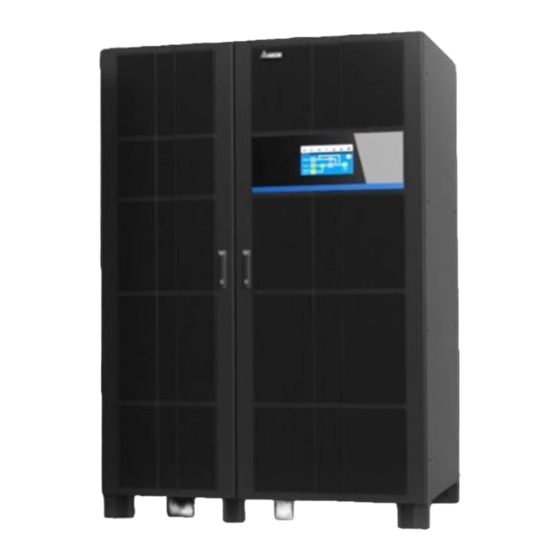
Page 15: Exterior & Dimensions
Exterior & Dimensions (Figure 2-1: UPS Exterior & Dimensions) Front View (Figure 2-2: Front View) -
Page 16: Internal View
(Figure 2-3: How to Open the Front Doors) Internal View WARNING: Only authorized Delta engineers or service personnel can perform installation, wiring, panel & cover removal, maintenance and operation. If you want to execute any action mentioned above by yourself, the action must be under the supervision of authorized Delta engineers or service personnel. - Page 17 Item After removing the wiring cover and opening the fan door (hinged on the right ❶/❻ side), you will see the wiring terminals shown in Figure 2-5 ~ Figure 2-7. For detailed information about the communication interfaces, please refer to ❷...
- Page 18 (Figure 2-6: Battery Input Terminals) (Figure 2-7: UPS Output, PE ( ) & GND ( ) Terminals) Modulon DPH Series...
-
Page 19: Tri-Color Led Indicator & Buzzer
Tri-color LED Indicator & Buzzer (Figure 2-8: Tri-color LED Indicator Location) NOTE: For information about the 10” color touch panel, please refer to 7. LCD Display & Settings. The buzzer is located at the rear of the system cabinet’s front door. (Figure 2-9: Buzzer Location) - Page 20 ‘Softstart’ • Indicates a warning message. Warning Level Buzzer Frequency Sounds for 0.5 second Minor every 3 seconds. Sounds for 0.5 second Medium every second. • Indicates a warning message. Warning Level Buzzer Frequency Major Long beep. Modulon DPH Series...
-
Page 21: Chapter 3 : Operation Modes
Green mode. NOTE: 1. The UPS must be connected with an external maintenance bypass cabinet (user-supplied, handled and configured by Delta service personnel). For the external maintenance bypass cabinet’s information, please refer to 1.2 Connection Warnings. 2. In this user manual, Q1, Q2, Q3, Q4 and Q5 represent the following. -
Page 22: Battery Mode
During the conversion process, output voltage remains the same. During Battery mode, the UPS’s tri-color LED illuminates yellow and the text ‘Battery’ appears in the upper right corner of the LCD screen. (Figure 3-2: Battery Mode Diagram) Modulon DPH Series... -
Page 23: Bypass Mode
Bypass Mode When the inverter encounters abnormal situations such as over temperature, overload, short circuit, abnormal output voltage or low battery, it will automatically shut itself down. If the UPS detects the bypass input is normal, it will automatically switch to Bypass mode to protect the connected critical loads from power interruption. -
Page 24: Eco Mode
During Frequency Conversion mode, the UPS’s tri-color LED illuminates green and the text ‘Frequency Conversion’ appears in the upper right corner of the LCD screen. (Figure 3-6: Frequency Conversion Mode Diagram) Modulon DPH Series... -
Page 25: Green Mode
Green Mode After the UPS is manually set as Green mode via the LCD, the system will automatically detect the output status (i.e. total load capacity %) to decide which specific power module(s) should be fully powered on or idle in order to achieve higher efficiency of the UPS. During Green mode, the UPS’s tri-color LED illuminates green and the text ‘Green’... -
Page 26: Chapter 4 : Communication Interfaces
Cabinet with Its Front Door Open (Figure 4-1: Communication Interfaces I) Item Q’ty ❶ Dry Contact Card 1 PC ❷ Parallel Communication Card 2 PCS ❸ SMART Slot 1 PC ❹ System Control Card 1 PC ❺ Auxiliary Power Card 2 PCS Modulon DPH Series... -
Page 27: Display Port
4.1.1 Display Port Before shipment, the display port has been connected to the 10” touch panel with the designated cable in Delta factory. 4.1.2 REPO Dry Contacts Connect the REPO dry contacts to a user-supplied switch and you can remotely shut down the UPS when an emergency occurs. -
Page 28: External Battery Temperature Detection
You can use the external battery temperature detection (BT1, BT2, BT3 and BT4) to detect a maximum of four external battery cabinets’ temperature. You need to purchase the battery cabinet temperature sensor cable (optional). (Figure 4-5: External Battery Temperature Detection) Modulon DPH Series... -
Page 29: External Switch/ Breaker Status Dry Contacts
4.1.4 External Switch/ Breaker Status Dry Contacts There are four sets of external switch/ breaker status dry contacts (S1, S2, S3 and S4), which can be used to respectively detect the status of input, bypass, output and manual bypass switches or breakers. Please follow the table below to connect the dry contacts to normally open (NO) or normally closed (NC) devices. -
Page 30: Output Dry Contacts
Please refer to the table below and 7.6.6 Dry Contact Setting. NOTE: Since the output dry contacts belong to the secondary circuit, the voltage of each dry contact’s connected device should not exceed 60Vdc/ 42Vac to avoid electric shock or insufficient insulation. Modulon DPH Series... - Page 31 (Figure 4-7: Output Dry Contacts & Schematic) Event Description None No set-up. Load On Inverter The UPS works in On-Line mode. Load On Bypass The UPS works in Bypass mode. When the main AC source fails, the batteries Load On Battery supply power to the critical loads.
- Page 32 When the UPS’s bypass SCR has a short-circuit issue, the UPS will send a signal to the Backfeed Protection connected external shunt trip device to cut off the backfeed voltage. When any UPS alarm occurs, the UPS will send General Alarm a signal. Modulon DPH Series...
-
Page 33: Input Dry Contacts
4.1.6 Input Dry Contacts There are four sets of programmable input dry contacts. The input dry contacts allow the UPS to receive external signals from peripheral devices and let the UPS response accordingly. Please use the touch panel to set each dry contact as normally open (NO) or normally closed (NC). -
Page 34: Parallel Communication Cards
Turn off the charger. NOTE: If you use non-Delta lithium-ion batteries, you must set up Charger Off. Please refer to 7.6.6 Dry Contact Setting. For settings relevant to the non-Delta lithium- ion batteries, please refer to 7.6.4 Battery & Charging Setting. For more information, please contact Delta customer service. -
Page 35: Parallel Ports
Please refer to 5.4.4 Parallel Units Wiring to route the parallel cables. WARNING: One parallel cable is provided in each UPS’s accessory package. Using non-Delta parallel cables to parallel UPSs may cause failure, malfunctions and accidents. (Figure 4-10: Location of the Parallel Ports) 4.1.9... -
Page 36: 4.1.10 Usb Port & Rs-232 Port
2. If you use the Delta lithium-ion batteries, you must install the optional multifunctional communication card (MFC) into the SMART slot to monitor the battery status. For settings and information relevant to the Delta lithium-ion batteries, please refer to 7.6.4 Battery &... -
Page 37: 4.1.12 Battery Start Buttons
(Figure 4-13: Location of the Auxiliary Power Cards) 4.1.12 Battery Start Buttons For the battery start buttons’ operation information, please refer to 6.2.2 Battery Mode Start- up Procedures. (Figure 4-14: Location of the Battery Start Buttons) Communication Interfaces II: at the Rear of the Touch Panel (Figure 4-15: Communication Interfaces II) -
Page 38: Cable Routing For The Communication Interfaces
Connects to a user-supplied environmental monitoring ❺ EMS/ CONSOLE system or Delta EnviroProbe 1000 (optional). There are two USB ports. Connect a user-supplied USB flash drive to any of the USB ports to (1) upgrade ❻ the UPS and LCD’s firmware and (2) download event (USB Port ×... -
Page 39: Chapter 5 : Installation And Wiring
Delta engineers or service personnel. If you use a forklift or other equipment to move the UPS, please make sure its load bearing is sufficient. Please refer to Table 5-1. - Page 40 UPS. 2. Do not hinder ventilation of the UPS. • Keep the installation area clean. Please note that wiring routes must be hermetic to prevent possible damage from rodents. Modulon DPH Series...
-
Page 41: Ups Installation
• Keep the installation area’s temperature around 77 ° F (25 ° C) and humidity within 95%. The highest operating altitude is 3280ft (1000 meters) above sea level. • For safety concerns, we suggest that you: 1. Equip surroundings of the installation area with CO or dry powder fire extinguishers. - Page 42 (optional), and install them at the rear of the UPS. Please follow the procedures below. ❶ Remove the UPS’s top cover and two rear panels. Keep the removed twenty M5 screws well for later use. (Figure 5-4: Remove the Top Cover and Two Rear Panels) Modulon DPH Series...
- Page 43 ❷ Remove the optional power exhaust cabinet’s two rear covers (including eight M4 screws) and install the covers on the top of the UPS. The tightening torque for M4 screws should be 17.4 ± 1.7 lb-in (20 ± 2 kgf-cm). (Figure 5-5: Install the Optional Power Exhaust Cabinet’s Two Rear Covers on the Top of the UPS)
- Page 44 UPS with the provided sixteen M5 screws packed in the two exhaust cabinets’ cartons. The tightening torque for M5 screws should be 30.4 ± 1.7 lb-in (35 ± 2 kgf- cm). (Figure 5-6: Connect the Exhaust Cabinets to the Rear of the UPS) Modulon DPH Series...
- Page 45 ❹ Install the two rear panels that you removed from the UPS to the rear of the power and system exhaust cabinets. The tightening torque for M5 screws should be 30.4 ± 1.7 lb-in (35 ± 2 kgf-cm). (Figure 5-7: Install the Two Rear Panels)
- Page 46 The tightening torque for M8 screws should be 130 ± 4.4 lb-in (150 ± 5 kgf-cm). (Figure 5-8: Install the Seismic Kits on the Top) Modulon DPH Series...
- Page 47 ❻ Follow the figure below to fix the UPS against the wall. (Figure 5-9: Fix the UPS against the Wall) ❼ Fix the three stands at the front bottom of the UPS on the ground. Each stand requires a M12 expansion bolt (provided by qualified service personnel). Refer to Figure 5-2 and Figure 5-3.
-
Page 48: Wiring
UPS in the designated installation area firmly. 2. Before wiring, please read 5.4 Wiring thoroughly. 3. Only authorized Delta engineers or service personnel can perform installation, wiring, panel & cover removal, maintenance and operation. If you want to execute any action mentioned above by yourself, the action must be under the supervision of authorized Delta engineers or service personnel. - Page 49 DPH Series 200kVA/ 250kVA/ 300kVA/ 350kVA/ UPS Capacity 200kW 250kW 300kW 350kW 3/0 AWG 4/0 AWG 300 kcmil 4/0 AWG (L1/ × 2 PCS × 2 PCS × 2 PCS × 3 PCS (70 mm (95 mm (150 mm (95 mm ×...
- Page 50 × 4 PCS × 4 PCS × 4 PCS × 4 PCS Maximum (+/ -) cable size (185 mm (185 mm (185 mm (185 mm × 4 PCS) × 4 PCS) × 4 PCS) × 4 PCS) Modulon DPH Series...
- Page 51 DPH Series 200kVA/ 250kVA/ 300kVA/ 350kVA/ UPS Capacity 200kW 250kW 300kW 350kW 400 kcmil 400 kcmil 400 kcmil 400 kcmil × 1 PC × 1 PC × 1 PC × 1 PC Maximum (PE) cable size (185 mm (185 mm...
- Page 52 542A 602A 350 kcmil 4/0 AWG 250 kcmil (L1/ Output × 2 PCS × 3 PCS × 3 PCS Recommended cable size (177 mm (95 mm (120 mm × 2 PCS) × 3 PCS) × 3 PCS) Modulon DPH Series...
- Page 53 DPH Series 400kVA/ 450kVA/ 500kVA/ UPS Capacity 400kW 450kW 500kW 1/0 AWG 1/0 AWG 2/0 AWG × 1 PC × 1 PC × 1 PC Recommended cable (PE) size (50 mm (50 mm (67 mm × 1 PC) × 1 PC) ×...
- Page 54 Bypass Breaker or Switch (Q2) External Maintenance Bypass Cabinet’s 800A 900A 1000A Manual Bypass Breaker or Switch (Q3) External Maintenance Bypass Cabinet’s 800A 900A 1000A Output Breaker or Switch (Q4) External Battery Cabinet’s Breaker (Q5) 1000A 1200A 1200A Modulon DPH Series...
- Page 55 NOTE: 1. Please follow local regulations to install a suitable conduit and bushing for cable protection. 2. Please refer to national and local electrical codes for acceptable protective devices and cable sizes. 3. The cables mentioned in Table 5-2 are copper wires, and each cable size is based on (1) cable type THHN &...
-
Page 56: Single Input To Dual Input Modification
Single Input to Dual Input Modification WARNING: Only authorized Delta engineers or service personnel can modify single input to dual input setup. The UPS default setting is single input. If you want to modify it into dual input, please follow the steps below. -
Page 57: Single Unit Wiring
Connect to the external maintenance bypass cabinet’s (L1/ L2/ L3) output breaker or switch (Q4). Connect to the external battery cabinet(s). Please Battery Input Terminals contact Delta service personnel for battery (+/ -) configurations. Connects to the external maintenance bypass cabinet’s PE (protective earth) GND terminal ( ). - Page 58 1.2 Connection Warnings for relevant information. The PE (protective earth) connection ensures that all exposed conductive surfaces are at the same electric potential as the Earth to avoid the risk of electrical shock due to leakage current or an insulation fault. Modulon DPH Series...
-
Page 59: Single Input (Single Unit)
5.4.3.1 Single Input (Single Unit) When there is only one AC power source, single unit wiring procedures are as follows. Step 1 Make sure that the external maintenance bypass cabinet’s Input Breaker or Switch (Q1), Bypass Breaker or Switch (Q2), Manual Bypass Breaker or Switch (Q3) and the Output Breaker or Switch (Q4) are in the OFF position. - Page 60 C. For cables that need connecting to the wiring terminals shown in Figure 2-5 ~ Figure 2-7, route the cables from the top of the cabinet and connect the cables to the wiring terminals. (Figure 5-13: Top Cable Entry for the Wiring Terminals) Modulon DPH Series...
- Page 61 Bottom Wiring: A. Open the UPS’s right front door, remove the wiring terminal cover and signal cable cover, and open the fan door (hinged on the right side). (Figure 5-14: Remove the Wiring Terminal Cover & Signal Cable Cover, and Open the Fan Door) B.
- Page 62 D. For cables that need connecting to the wiring terminals shown in Figure 2-5 ~ Figure 2-7, route the cables from the bottom of the cabinet and connect the cables to the wiring terminals. (Figure 5-17: Bottom Cable Entry for the Wiring Terminals) Modulon DPH Series...
- Page 63 Step 6 Connect the cables of the main AC source, output and external battery cabinet(s) to the UPS and the external maintenance bypass cabinet. Please refer to Table 5-3, Table 5-4, 5.5 External Battery Cabinet Connection Warnings and the following diagram to perform wiring.
-
Page 64: Dual Input (Single Unit)
5-3, Table 5-4, 5.5 External Battery Cabinet Connection Warnings and the following diagram to perform wiring. (Figure 5-20: Single Unit Dual Input Wiring Diagram) Step 4 Refer to Figure 5-19 to ground the UPS, external battery cabinet(s) and connected critical loads. Modulon DPH Series... -
Page 65: Parallel Units Wiring
5.4.4 Parallel Units Wiring NOTE: 1. Up to three UPS units can be paralleled for redundancy and capacity expansion. Only the UPSs with the same capacity, voltage, frequency and version can be paralleled. Please only use the provided parallel cable to parallel the UPS units. - Page 66 Before start-up of the parallel units, qualified service personnel must set each UPS’s 'Parallel Group ID' (1 or 2) and 'Parallel ID' (1 ~ 8) through the LCD. Otherwise, the parallel UPSs cannot be started. Please refer to 7.6.5 Parallel Setting. Modulon DPH Series...
-
Page 67: External Battery Cabinet Connection Warnings
For relevant information, please refer to the manual of the lithium-ion batteries. 2. Whether you use the lead-acid batteries or the lithium-ion batteries, please contact Delta service personnel for any battery/ battery cabinet’s setup and configurations. WARNING: ... - Page 68 There are four installation methods for selection. A 3-pole DC circuit breaker or DC isolated switch connected in series with DC fuses A 2-pole DC circuit breaker or DC isolated switch connected in series with DC fuses Modulon DPH Series...
- Page 69 NOTE: 1. Table 5-5 is for 12Vdc × 40 PCS of batteries (default). If you install a different number of batteries, please contact Delta service personnel for the protective device’s current and voltage. 2. If you need to parallel multiple units of external battery cabinets, please contact Delta service personnel for relevant information.
- Page 70 • The protective device is optional, and its type must be fast-acting DC circuit breaker and/ or fast-acting DC fuse. If you want to buy any of them, please contact Delta service personnel. When choosing the protective device, please follow the instructions below.
- Page 71 External Battery Cabinet’s Protective Device (Option 2) (Figure 5-24: Installation of a 2-pole DC Circuit Breaker or DC Isolated Switch Connected in Series with DC Fuses) External Battery Cabinet’s Protective Device (Option 3) (Figure 5-25: Installation of a 3-pole DC Circuit Breaker) External Battery Cabinet’s Protective Device (Option 4) (Figure 5-26: Installation of a 2-pole DC Circuit Breaker)
- Page 72 For relevant information, please refer to the user manual of the lithium-ion batteries. Whether you use the lead-acid batteries or the lithium-ion batteries, please contact Delta service personnel for any battery/ battery cabinet’s setup and configurations. For common battery application, please install a protective device between each parallel UPS and its connected external battery cabinet(s).
- Page 73 (Figure 5-27: Common Battery Diagram) • External Battery Cabinet Alarm When any external battery cabinet connected to the UPS has the following problems, the UPS system will sound an alarm. Please see the table below. External Battery Cabinet Status Alarm Battery Abnormal - Reversed Sounds for 0.5 second every second.
-
Page 74: Sts Module
Long beep. Battery Life Time Expired Sounds for 0.5 second every 3 seconds. STS Module The STS module has been installed in the UPS by default. Please refer to Figure 2-4 for its location. (Figure 5-28: STS Module) Modulon DPH Series... -
Page 75: Sts Module Installation
5.6.1 STS Module Installation WARNING: 1. Only when (1) the UPS runs in manual bypass mode, (2) the capacitors are completely discharged and (3) the battery power is completely cut off can qualified service personnel perform the following installation procedures. 2. - Page 76 ( ❹ ) and push them inwards in order to push the module into the slot. Once the module snaps into place, the pullers are in the closed status. (Figure 5-31: Insert the STS Module into the Slot) Modulon DPH Series...
- Page 77 Step 3 Re-install the four screws (removed during the STS module removal process) to firmly fix the STS module's ear brackets on the UPS cabinet. (Figure 5-32: Fix the STS Module on the UPS Cabinet) Step 4 Turn the STS module’s switch to the upper position ( (Figure 5-33: Turn the STS Module’s Switch to the Upper Position)
-
Page 78: Sts Module Removal
) and wait until the STS module’s LED indicator becomes off. (Figure 5-34: Turn the STS Module’s Switch to the Lower Position) Step 2 Remove the four screws from the STS module. (Figure 5-35: Remove the Four Screws) Modulon DPH Series... - Page 79 Step 3 Arrange two persons to remove the STS module. One person holds the STS module’s two pullers and opens them outward (❶); at this moment, the STS module should come out from the slot a little bit (❷). Next, one person holds the upper handle and the other holds the lower one (❸) and two persons work together to pull out the STS module from the slot.
-
Page 80: Sts Module's Led Indicator
( ), the STS module will shut down, and its output and LED indicator will be off. Power Module (Optional) The power module is optional. Each capacity is 50kVA/ 50kW. (Figure 5-38: Power Module (Optional)) Modulon DPH Series... -
Page 81: Power Module Installation
2. The power module is heavy (78.3 lb (35.5 kg)). At least two people are required for handling. 3. Please follow your UPS capacity to install the correct number of power modules. DPH Series 200kVA/ 250kVA/ 300kVA/ 350kVA/... - Page 82 (Figure 5-39: Confirm the Power Module’s Switch in the Lower Position) Step 2 Use the eight M4 screws to fix the two ear brackets on the two sides of the power module. (Figure 5-40: Install the Two Ear Brackets) Modulon DPH Series...
- Page 83 Step 3 Insert the power module into the power module slot until it snaps into place. (Figure 5-41: Insert the Power Module into the Slot) Step 4 Use the four M6 screws to firmly fix the power module on the UPS cabinet. (Figure 5-42: Fix the Power Module on the UPS Cabinet)
-
Page 84: Power Module Removal
3. The power module is heavy (78.3 lb (35.5 kg)). At least two people are required for handling. Step 1 Turn the power module’s switch to the lower position ( ) and wait until the power module’s LED indicator becomes off. (Figure 5-44: Turn the Power Module’s Switch to the Lower Position) Modulon DPH Series... - Page 85 Step 2 Remove the four screws from the power module. (Figure 5-45: Remove the Four Screws) Step 3 Pull out the power module from the slot. When the power module cannot be pulled out any more, press the lock on the left side of the power module to continuously pull out the module from the UPS cabinet.
-
Page 86: Power Module's Led Indicator
DC BUS voltage until the voltage reaches to a safety level. After that, the power module’s LED indicator will be off. Auxiliary Module The auxiliary module has been installed in the UPS by default. Please refer to Figure 2-4 for its location. (Figure 5-48: Auxiliary Module) Modulon DPH Series... -
Page 87: Auxiliary Module Installation
5.8.1 Auxiliary Module Installation WARNING: Only when (1) the UPS runs in manual bypass mode, (2) the capacitors are completely discharged and (3) the battery power is completely cut off can qualified service personnel perform the following installation procedures. Step 1 Confirm that the auxiliary module’s switch is in the lower position ( (Figure 5-49: Confirm the Auxiliary Module’s Switch in the Lower Position) Step 2... -
Page 88: Auxiliary Module Removal
Auxiliary Module Removal WARNING: Only when (1) the UPS runs in manual bypass mode, (2) the capacitors are completely discharged and (3) the battery power is completely cut off can qualified service personnel perform the following removal procedures. Modulon DPH Series... - Page 89 Step 1 Turn the auxiliary module’s switch to the lower position ( ) and wait until the auxiliary module’s LED indicator becomes off. (Figure 5-53: Turn the Auxiliary Module’s Switch to the Lower Position) Step 2 Remove the four screws from the auxiliary module. (Figure 5-54: Remove the Four Screws)
-
Page 90: Auxiliary Module's Led Indicator
If you turn the auxiliary module’s switch to the lower position ( ), the bypass magnetic contactor will be tripped off and the auxiliary module’s LED indicator will be off. At the same time, the STS module will shut down its output. Modulon DPH Series... -
Page 91: Chapter 6 : Ups Operation
4. The external battery cabinet’s breaker (Q5) shown on the LCD is always ON by default. To enable the detection of the Q5 status via the LCD, please contact Delta customer service for additional configurations. • Pre Start-up Warnings 1. Before UPS operation, ensure that installation and wiring have been completely done according to 5. -
Page 92: Start-Up Procedures
Tap the ON/ OFF Button ( ) on the LCD screen. Step 6 After the inverter turns on, the UPS will run in On-Line mode, the LCD screen will show as below, and the tri-color LED indicator will illuminate green. Modulon DPH Series... -
Page 93: Battery Mode Start-Up Procedures
6.2.2 Battery Mode Start-up Procedures WARNING: Before turning on the UPS, please read 6.1 Pre Start-up & Pre Turn-off Warnings thoroughly and ensure that the precautions and instructions have been followed. Step 1 Ensure that the external maintenance bypass cabinet’s Manual Bypass Breaker or Switch (Q3) is in the OFF position. -
Page 94: Bypass Mode Start-Up Procedures
Switch ON the external maintenance bypass cabinet’s Output Breaker or Switch (Q4). Step 3 Switch ON the external maintenance bypass cabinet’s Bypass Breaker or Switch (Q2). Step 4 Now, the UPS runs in Bypass mode, the LCD screen shows as below, and the tri-color LED indicator illuminates yellow. Modulon DPH Series... -
Page 95: Manual Bypass Mode Start-Up Procedures
6.2.4 Manual Bypass Mode Start-up Procedures WARNING: 1. Before turning on/ off the UPS, please read 6.1 Pre Start-up & Pre Turn-off Warnings thoroughly and ensure that the precautions and instructions have been followed. 2. In Manual Bypass Mode, make sure that all of the switches/ breakers (except for the external maintenance bypass cabinet’s Manual Bypass Breaker/ Switch (Q3)) are in the OFF position before working on the UPS’s internal circuits to prevent electric shock. - Page 96 Tap the ON/ OFF Button ( ) on the LCD screen. Step 6 After the inverter turns on, the UPS will run in On-Line mode, the LCD screen will show as below, and the tri-color LED indicator will illuminate green. Modulon DPH Series...
-
Page 97: Eco Mode Start-Up Procedures
6.2.5 ECO Mode Start-up Procedures WARNING: Before turning on the UPS, please read 6.1 Pre Start-up & Pre Turn-off Warnings thoroughly and ensure that the precautions and instructions have been followed. Step 1 Ensure that the external maintenance bypass cabinet’s Manual Bypass Breaker or Switch (Q3) is in the OFF position. - Page 98 After the inverter turns on and the system confirms that the bypass voltage is normal, the UPS will automatically transfer to ECO mode to let the bypass supply power, the LCD screen will show as below, and the tri-color LED indicator will illuminate green. Modulon DPH Series...
-
Page 99: Frequency Conversion Mode Start-Up Procedures
6.2.6 Frequency Conversion Mode Start-up Procedures WARNING: 1. Before turning on the UPS, please read 6.1 Pre Start-up & Pre Turn-off Warnings thoroughly and ensure that the precautions and instructions have been followed. 2. Frequency Conversion mode is only applicable to single UPS but not to parallel UPSs. - Page 100 After the inverter turns on, the UPS will run in Frequency Conversion mode, the output frequency will be the same as the setup value, the LCD screen will show as below, and the tri- color LED indicator will illuminate green. Modulon DPH Series...
-
Page 101: Green Mode Start-Up Procedures
6.2.7 Green Mode Start-up Procedures WARNING: Before turning on the UPS, please read 6.1 Pre Start-up & Pre Turn-off Warnings thoroughly and ensure that the precautions and instructions have been followed. Step 1 Ensure that the external maintenance bypass cabinet’s Manual Bypass Breaker or Switch (Q3) is in the OFF position. - Page 102 (i.e. total load capacity %) to decide which specific power module(s) should be fully powered on or idle in order to achieve higher efficiency of the UPS. The LCD screen shows as below, and the tri-color LED indicator illuminates green. Modulon DPH Series...
-
Page 103: Turn-Off Procedures
Turn-off Procedures 6.3.1 On-Line Mode Turn-off Procedures WARNING: Before turning off the UPS, please read 6.1 Pre Start-up & Pre Turn-off Warnings thoroughly and ensure that the precautions and instructions have been followed. Step 1 Tap the ON/ OFF Button ( ) to shut down the UPS’s inverter. -
Page 104: Bypass Mode Turn-Off Procedures
Wait for the UPS to complete the DC BUS discharging. After that, switch OFF each external battery cabinet's breaker (Q5), and the LCD and tri-color LED indicator will be off. Step 4 Switch OFF the external maintenance bypass cabinet’s Output Breaker or Switch (Q4). Modulon DPH Series... -
Page 105: Frequency Conversion Mode Turn-Off Procedures
6.3.6 Frequency Conversion Mode Turn-off Procedures WARNING: Before turning off the UPS, please read 6.1 Pre Start-up & Pre Turn-off Warnings thoroughly and ensure that the precautions and instructions have been followed. Step 1 Please make sure that the critical loads connected to the UPS have already been safely shut down. -
Page 106: Start-Up & Turn Off Procedures For Parallel Units
Parallel Group ID no. and the same parameters for the input, output and battery settings. Tap the icon ( ) to check if the Parallel Group ID no. and Parallel ID no. are set properly. The UPS with the smallest Parallel ID no. is the master UPS. Modulon DPH Series... - Page 107 Ensure that the output voltage difference between each parallel UPS is below 3V. Only authorized Delta engineers or service personnel can check the output voltage difference, or it must be done under the supervision of authorized Delta engineers or service personnel. Step 5 Now, the UPSs are ready to operate in parallel.
-
Page 108: Chapter 7 : Lcd Display & Settings
DI1 ~ DI4 DC BUS Voltage PM A/D PM D/D Temperature PM D/A Humidity DI1 ~ DI4 (Level 2) UPS Output Line Voltage (V) Current (A) Frequency (Hz) Load (%) Apparent Power (kVA) Active Power (kW) Power Factor Modulon DPH Series... - Page 109 (Level 1) SETUP (Level 2) (Level 2) Dry Contact Bypass Setting Setting Bypass Frequency Range INPUT DRY CONTACT: 1 ~ 4 Bypass Voltage (Max) OUTPUT DRY CONTACT: 1 ~ 6 Bypass Voltage (Min) ECO Voltage Range (±%) (Level 2) General Setting (Level 2) Mode Setting Date/ Time...
- Page 110 POWER MODULE MCU INV Temp. (°C) PFC Temp. (°C) SOH of DC CAP (%) *3 Current of INV AC CAP (A) *3 Fan Speed (rpm) *3 Exhaust Fan Exhaust Fan Group # (rpm) (Figure 7-1: LCD Display Hierarchy) Modulon DPH Series...
-
Page 111: How To Turn On The Lcd
To display the item(s), you have to log in as Administrator. Please refer to 7.4 Password Entry. The item(s) will show up only when you use the Delta lithium-ion batteries and have installed the optional multifunctional communication card (MFC) in the SMART slot. -
Page 112: Introduction Of Touch Panel And Function Keys
Introduction of Touch Panel and Function Keys Modulon DPH Series... - Page 113 Text/ Button Symbol Digital Function Display Icon/ Text Display Description (Yes or (Yes or (Yes or Tap the button to go back to the Main Screen. The figure ( ) below the icon ) indicates the parallel group ID no. (former) and the parallel ID no.
- Page 114 Indicates the UPS's current operation mode. Tap the button to check the power flow diagram and the operation status of the UPS. Tap the button to check the Input, Output, and Battery summary status of the UPS. Modulon DPH Series...
- Page 115 Text/ Button Symbol Digital Function Display Icon/ Text Display Description (Yes or (Yes or (Yes or Tap the button to check the auxiliary module status, STS module status, power module status, auxiliary power card status, system control card status and parallel communication card status.
- Page 116 Other icons on the touch panel are shown in the table below. Icon Function Goes to the top page. Goes to the last page. Moves up. Moves down. Goes to the previous page. Goes to the next page. Modulon DPH Series...
- Page 117 Icon Function Increase. Decrease. 1. Indicates the page no. 2. Choose to go to a specific page no. Delete. Capital. Space. NOTE: 1. After the backlight is turned off, you can tap the LCD to return to the Main Screen. 2.
-
Page 118: Password Entry
→ Admin Password (4 digits). Check Kilowatt-Hour Path: → Main Input → kWh Icon ( Tap the kWh icon ( ), and you can check the kWh statistics of the UPS main input in the following window. Modulon DPH Series... - Page 119 Item Description Sheet Tabs Tap the sheet tabs to view the kWh statistics and (Day/ Week/ Month/ column charts of different time scales. Year/ Since Reset) 1. Shows the UPS’s main input kWh statistics, with time on X-axis and kWh on Y-axis. Column Chart 2.
-
Page 120: Ups Settings
Please note that the Frequency output will be terminated once the inverter is turned off. Conversion Mode NOTE: Frequency Conversion mode is only applicable to single UPS but not to parallel UPSs. Modulon DPH Series... -
Page 121: Output Setting
7.6.3 Output Setting Path: → Output Setting Item Description Voltage Set up the output voltage. When the UPS is distant from the loads and there is a voltage drop Voltage in the output, you can adjust the INV output voltage amplitude for Compensation voltage compensation. -
Page 122: Battery & Charging Setting
If you use the Delta lithium-ion batteries, please set up the battery type as 'LiB (Integration)'. The item 'LiB (Integration)' will only appear on the LCD if you use the Delta lithium-ion batteries with the optional multifunctional communication card (MFC) being installed in the SMART slot. Please contact Delta customer service if you need more information. - Page 123 Item Description Set up the restored voltage. NOTE: 1. The item will only show up if the Battery Type is set as 'LiB (Integration)'. When the remaining Restored Voltage battery voltage reaches the setup restored voltage, the UPS will automatically activate the charger to re-charge the batteries.
-
Page 124: Parallel Setting
5. Active Standby (normally closed) for Input Dry Contact 3 6. Battery Abnormal Shutdown each input dry Input Dry Contact 4 7. Input Transformer OTW contact. 8. Output Transformer OTW 9. Battery Fuse Open 10. Charge Off Modulon DPH Series... - Page 125 Output Dry Event Selection Type Contact No. 1. None 2. Load On Inverter 3. Load On Bypass 4. Load On Battery 5. Battery Low 6. Battery Input Abnormal 7. Battery Test Fail 8. Internal Comm. Fail Output Dry Contact 1 9.
-
Page 126: General Setting
LCD, and the alarm message 'Replace Dust Filter' Dust Filter will be displayed. Replacement Date NOTE: Only when you select 'Enable' for 'Dust Filter Installation' can you set up the item. Modulon DPH Series... -
Page 127: Ip Setting
7.6.8 IP Setting Path: → IP Setting Item Description DHCP Client Enable or disable the DHCP client. IP Address Set up the IP address. Subnet Mask Set up the subnet mask. Gateway IP Set up the gateway IP address. DNS 1 IP Set up the DNS server 1 IP address. -
Page 128: 7.6.10 Network Service
Path 1: → Warning Path 2: When there is a warning, the buzzer icon ( ) will light up in red, and the buzzer will sound. Tap the warning icon ( ) to enter the WARNING screen. Modulon DPH Series... -
Page 129: Historical Event
7.7.2 Historical Event Path: → Historical Event 7.7.3 Statistics Path: → Statistics Item Description In Battery Mode Shows how many times the UPS runs in Battery mode. Battery Mode Shows how long the UPS runs in Battery mode. Duration Shows how many times the UPS runs in Bypass mode. In Bypass Mode Bypass Mode Shows how long the UPS runs in Bypass mode. -
Page 130: Clear
SOH of DC CAP (%)* specific power module. Shows the INV AC CAP’s current of a specific Current of INV AC CAP (A) * power module. Fan Speed (rpm) * Shows a specific power module’s fan speed. Modulon DPH Series... -
Page 131: Version & S/N
Description Exhaust Exhaust Fan Group # (rpm) Shows a specific exhaust fan speed. NOTE: This function is optional. If you need to activate it, please contact Delta customer service. 7.7.7 Version & S/N NOTE: To operate the UPSs in parallel, please make sure all the versions below are the same for each parallel unit. -
Page 132: Chapter 8 : Optional Accessories
Parallel Cable Connects the parallel UPSs. (20-meter long) If you use the Delta lithium-ion batteries, you must purchase and install the multifunctional communication card (MFC) in the SMART slot shown in Figure 4-1 to monitor the battery status via the UPS’s LCD. For relevant information, please refer to 8.2 MFC Function on the LCD Screen. -
Page 133: Ems Function On The Lcd Screen
Item Function Helps to exhaust the air from the top of the UPS when the UPS is installed against the wall. It should be used together Power Exhaust with the optional system exhaust cabinet, and installed at the Cabinet rear of the UPS. For relevant information, please refer to 5.3 UPS Installation. - Page 134 Comm DIP Switch Settings of the EnviroProbe 1000 Quick Guide. 3. When installing, please set the ID # by the four ID DIP switches on the left of the device following 3-2 ID DIP Switch Settings of the EnviroProbe 1000 Quick Guide. Modulon DPH Series...
- Page 135 NOTE: The ID # of each EMS 1000 (EnviroProbe) device connected to the UPS must be different so that the UPS can identify each device. 4. To enable the EMS function, you have to set up relevant items on the LCD after connecting the optional EMS 1000 (EnviroProbe) to the UPS.
- Page 136 1. Set each input contact as Normally Open (NO)/ Normally Closed (NC). Input Contact 2 INPUT 2. Set the title for each input contact. CONTACT Input Contact 3 3. Set the event type as None/ Information/ Warning/ Alarm. Input Contact 4 Modulon DPH Series...
-
Page 137: Mfc Function On The Lcd Screen
The PAGE 3 & MFC screens (see the figures below) will only appear on the LCD if you use the Delta lithium-ion batteries with the optional multifunctional communication (MFC) card being installed in the SMART slot (see Figure 4-1). Please contact Delta customer service if you need more information. - Page 138 Set up the MODBUS baud rate for the optional Rate multifunctional communication card (MFC). Path: → Version & S/N Item Sub Item Description Check and update the MCU firmware version of the optional multifunctional communication card (MFC). Modulon DPH Series...
-
Page 139: Chapter 9 : Maintenance
Batteries • The DPH series UPS uses the lead-acid batteries or the lithium-ion batteries. Make sure to replace the batteries according to battery life. However, the actual battery life depends on the environment temperature, usage, and charging/ discharging frequency. High temperature environments and high charging/ discharging frequency will quickly shorten the battery life;... -
Page 140: Appendix 1 : Technical Specifications
Power Factor Output Frequency 50/60 Hz ≤ 105%: continuous > 105% ~ 110%: 60 minutes, Overload > 110% ~ 125%: 10 minutes; Capability > 125% ~ 150%: 1 minute; > 150%: 1 second Display 10” Touch Panel Modulon DPH Series... - Page 141 Model 200kVA/ 250kVA/ 300kVA/ 350kVA/ UPS Capacity 200kW 250kW 300kW 350kW External battery temperature dry contact × 4, External switch/breaker status dry contact × 4, Output dry contact × 6, Input dry contact × 4, Interface Standard Parallel port × 4, USB type A × 2, USB type B ×...
- Page 142 408 ~ 552 Vac (full load) Current Harmonic ≤ 3% * Input Distortion Power Factor > 0.99 Frequency Range 40 ~ 70 Hz Voltage 480 Vac (3Φ3W + G) Output Voltage Harmonic ≤ 1% (linear load) Distortion Modulon DPH Series...
- Page 143 Model 400kVA/ 450kVA/ 500kVA/ UPS Capacity 400kW 450kW 500kW Power Factor Frequency 50/60 Hz Output ≤ 105%: continuous (Continued) > 105% ~ 110%: 60 minutes, Overload > 110% ~ 125%: 10 minutes; Capability > 125% ~ 150%: 1 minute; > 150%: 1 second Display 10”...
- Page 144 When input vTHD is < 1%. 2. * At a distance of 3.28 ft (1 meter) of the UPS. 3. Please refer to the rating label for the safety certification. 4. All specifications are subject to change without prior notice. Modulon DPH Series...
-
Page 145: Appendix 2 : Warranty
Appendix 2 : Warranty Seller warrants this product, if used in accordance with all applicable instructions, to be free from original defects in material and workmanship within the warranty period. If the product has any failure problem within the warranty period, Seller will repair or replace the product at its sole discretion according to the failure situation. - Page 147 - Regional Office The United States Australia Delta Electronics (Americas) Ltd. Delta Energy Systems Australia Pty Ltd. 46101 Fremont Blvd. Fremont, CA 94538 Unit 20-21, 45 Normanby Road, Notting Hill VIC 3168, Australia T +1 510 344 2157 T +61 3 9543 3720 E ups.na@deltaww.com...
- Page 148 5013294400...
Need help?
Do you have a question about the DPH Series and is the answer not in the manual?
Questions and answers