ProFire PF2200-SB Product Manual
Single burner controller
Hide thumbs
Also See for PF2200-SB:
- Product manual (98 pages) ,
- Installation manual (40 pages) ,
- User manual (21 pages)
Table of Contents
Advertisement
Advertisement
Table of Contents

Related Manuals for ProFire PF2200-SB


Summary of Contents for ProFire PF2200-SB
- Page 1 V 4.0 PF2200-SB PRODUCT MANUAL Page 1 of 85...
-
Page 2: Table Of Contents
V 4.0 PROPRIETARY INFORMATION: THIS DOCUMENT IS PREPARED BY PROFIRE ENERGY FOR THE USE OF OUR CUSTOMER. PROFIRE ENERGY ASSUMES NO LIABILITY TO ANY OTHER PARTY FOR ANY REPRESENTATIONS CONTAINED HEREIN. Table of Contents INTRODUCTION ..............................4 SCOPE PURPOSE ..............................4 TERMS ABBREVIATIONS ............................. - Page 3 V 4.0 3.3.2 MOUNTING CARDS ............................... 49 3.3.3 PROTECTIVE EARTHING ..............................50 3.3.4 ELECTRICAL NOISE ................................ 50 OPERATIONS AND MAINTENANCE ........................51 ASSUMPTIONS SPECIFIC USE ..........................51 TRANSPORTATION & STORAGE CONDITIONS ......................51 OPERATOR USER INTERFACE ..........................51 4.3.1 SYSTEM NAVIGATION ..............................51 4.3.2 SETTINGS ..................................
-
Page 4: Introduction
INTRODUCTION SCOPE and PURPOSE This document is intended to be a full description of the PF2200-SB product and the intended use in accordance with the product life cycle. This document outlines the following: PF2200-SB Product Description: this section describes the intended use of the product; including •... -
Page 5: Terms And Abbreviations
V 4.0 TERMS and ABBREVIATIONS Alarm An indication of an abnormal condition in either the equipment or the process. Continuous Pilot A pilot which, once placed in operation, is intended to remain ignited continuously until it is manually interrupted Digital Input An input to the system that can be one of only two states (Energized or De-energized). - Page 6 V 4.0 Maximum Flame- Period of time between the signal indicating absence of flame and the signal to failure Re-ignition energize the ignition device. During this time period the fuel supply is not shut off. Time Non-volatile Condition such that a restart can only be accomplished by a manual reset of the Lockout system and by no other cause Permanent...
-
Page 7: Acronyms
PF2200-SB Model number for the PF2200 Single Burner BMS product. Consists of: BMS Card, User Interface Card, keypad, enclosure and ignition switch Profire Network. Method of communication between User Interface Card and BMS Card. Proof Test Coverage Pulse Width Modulation Resistive Thermal Device Safety Integrity Level. -
Page 8: Product Support
V 4.0 PRODUCT SUPPORT Product support can be obtained from: Profire Energy 1.855.776.3473 321 South, 1250 West Suite 1 Lindon, UT 84042, USA support@profireenergy.com RELATED LITERATURE PF2200 Single Burner BMS – Modbus Registers PF2200 Single Burner BMS – Software Release Notes... -
Page 9: Pf2200-Sb Product Description
PF2200-SB PRODUCT DESCRIPTION PRODUCT OVERVIEW The PF2200 Single Burner Controller (PF2200-SB) product is designed to provide safe and reliable control over industrial heating appliances. This product consists of five main pieces: User Interface Card: the card which provides interaction to the user / operator. This card •... -
Page 10: User Interface Card
Firmware Update screen on the User Interface and is limited by the size of USB stick-- a USB stick of size 1GB or larger is recommended. Firmware update is only supported using authorized firmware bundles. Contact Profire Energy for an authorized firmware bundle. -
Page 11: Bms Card
The BMS card provides the necessary I/O and functionality to reliably and safely control a burner. In addition, the BMS card also has tertiary features that are not safety rated but provide a functional benefit to the overall product. Section 2: PF2200-SB PRODUCT DESCRIPTION Page 11 of 85... - Page 12 Through the use of the rectification property of the flame, the PF2200-SB measures the presence of flame by applying an AC signal to the rod. If an open circuit event exists, the result will be a loss of flame.
- Page 13 The ESD input (terminals 33-34) is an energized-to-run digital input that is always enabled. If the contact is de-energized, the system will present an alarm and proceed to lockout (if running). If the contact is energized, the alarm will clear. Section 2: PF2200-SB PRODUCT DESCRIPTION Page 13 of 85...
- Page 14 Low trip with low pressure mode set to Main Main Permissive 4-20mA Permissive Low trip with low pressure mode set to Warning Warning Active range High trip with mains ON Alarm High trip with mains OFF Section 2: PF2200-SB PRODUCT DESCRIPTION Page 14 of 85...
- Page 15 Active range High trip with high trip mode set to wait Wait High trip with high trip mode set to warning Warning High trip with high trip mode set to alarm Alarm Section 2: PF2200-SB PRODUCT DESCRIPTION Page 15 of 85...
- Page 16 V 4.0 2.1.2.10 TEMPERATURE INPUTS The PF2200-SB has three distinct temperature inputs: Bath, Outlet and Stack; each of which are configurable to be either a Type-K thermocouple or PT-100 RTD input. Each of the three distinct temperature inputs mentioned above have the following set points that can be configured via the user interface (note: depending on the mode, the temperature input may or may not utilize all the set points below;...
- Page 17 The Proof of Closure input (terminals 11-12) is a digital input meant to be connected to a Proof of Closure switch, indicating the closure of the main valve(s). An energized Proof of Closure input indicates that the main valve is closed. The PF2200-SB monitors the Proof of Closure input and takes action, as outlined in the table below.
- Page 18 This contact is energized to run, meaning that a non-energized contact indicates a high pressure event. The high pressure functionality is outlined in the table below. Input Configuration Event System Behavior Disabled No Effect De-energized Alarm Enabled Energized Section 2: PF2200-SB PRODUCT DESCRIPTION Page 18 of 85...
- Page 19 (Max and Min) and can be configured as: Disabled, High Temp ESD, Process Control, or Display Only. For details on the individual modes and setpoints, see the Temperature Inputs section of this document. Section 2: PF2200-SB PRODUCT DESCRIPTION Page 19 of 85...
- Page 20 4-20mA input. If this input goes invalid or out of range the appliance firing rate will be set to 0% and an alarm will be set to shut the system down. Section 2: PF2200-SB PRODUCT DESCRIPTION Page 20 of 85...
- Page 21 No Effect Out of range Alarm Active range, system not in process No Effect control 4-20mA Run with process setpoint set by Active range, system in process control Process Setpoint Adjustment Input Section 2: PF2200-SB PRODUCT DESCRIPTION Page 21 of 85...
- Page 22 The TCV output also supports a manual override mode, where the output percentage is modifiable via the user interface. When in manual override mode, the TCV output percentage is mapped to the manual output position regardless of the system state. Section 2: PF2200-SB PRODUCT DESCRIPTION Page 22 of 85...
- Page 23 Process temperature is above low temp warning setpoint De-energized when tank level is above high level setpoint Level Control Energized when tank level is below high level setpoint minus dead band Section 2: PF2200-SB PRODUCT DESCRIPTION Page 23 of 85...
-
Page 24: Keypad
- Go back to the previous screen - Escape from setting combo boxes - Escape from setting spin boxes User interface navigation Alternates between the following three screens: Status, Settings, and System. Section 2: PF2200-SB PRODUCT DESCRIPTION Page 24 of 85... - Page 25 ANY safety function. If user shut-down is a required safety function, then the user input must be hard-wired into the ESD input of the BMS card. Section 2: PF2200-SB PRODUCT DESCRIPTION Page 25 of 85...
-
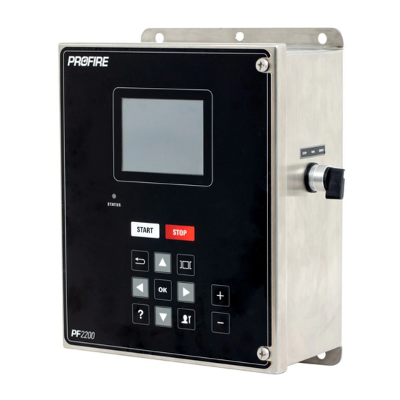
Page 26: Enclosure
V 4.0 2.1.4 ENCLOSURE There are two options of enclosure-types for the PF2200-SB product: PF2200-SB-A: Stainless Steel Enclosure • PF2200-SB-B: Polyester Enclosure (Not yet available) • Both enclosure styles cannot be opened without the use of a tool (screwdriver). 2.1.4.1... - Page 27 V 4.0 2.1.4.2 PF2200-SB-B Polyester Enclosure (Not yet available) Enclosure Construction Polyester Ingress Protection / NEMA Type 4X Temperature Rating -40 to +55⁰C Dimensions 12.15 x 9.64 x 5.28 “ Section 2: PF2200-SB PRODUCT DESCRIPTION Page 27 of 85...
-
Page 28: Operating Sequence
(default set to 3) is exceeded the system will shut down on Flame Fail Flame Loss event results in detecting an absence of flame that exceeds the Flame Failure • Lock-out Time Section 2: PF2200-SB PRODUCT DESCRIPTION Page 28 of 85... -
Page 29: Power On
Modbus Interface • In the Lockout state, the status of each powered outputs is as follows: Powered Output Status Pilot 1 / 2 De-energized Coil 1 / 2 De-energized De-energized De-energized Section 2: PF2200-SB PRODUCT DESCRIPTION Page 29 of 85... -
Page 30: Ready
In the Alarm state, the status of each powered outputs is as follows: Powered Output Status Pilot 1 / 2 De-energized Coil 1 / 2 De-energized De-energized De-energized Section 2: PF2200-SB PRODUCT DESCRIPTION Page 30 of 85... -
Page 31: Waiting
Any alarms or waits that occur during this still will force the system to go to the respective state (e.g. alarm or wait, respectively). In this system state, the status of each powered outputs is as follows: Section 2: PF2200-SB PRODUCT DESCRIPTION Page 31 of 85... -
Page 32: Pilot 1
In the Pilot state, the status of each powered outputs is as follows: Powered Output Status Pilot 1 Energized De-energized if disabled Pilot 2 Energized if enabled Coil 1 /2 De-Energized Section 2: PF2200-SB PRODUCT DESCRIPTION Page 32 of 85... -
Page 33: Main Light Off
In the Main Light Off state, the status of each powered outputs is as follows: Powered Output Status Pilot 1 Energized De-energized if disabled Pilot 2 Energized if enabled Coil 1 /2 De-Energized Section 2: PF2200-SB PRODUCT DESCRIPTION Page 33 of 85... -
Page 34: Process Control
In the case that the process temperature exceeded the setpoint, the temperature must fall below the setpoint minus the dead-band in order for the SSV outputs to re-energize. Note: this process control mode does not utilize the HFV or the TCV outputs. Section 2: PF2200-SB PRODUCT DESCRIPTION Page 34 of 85... - Page 35 4. When the process temperature cools down to the process temperature setpoint minus the dead band the SSV and the HFV outputs will be energized to heat the system back up Note: this process control mode does not utilize the TCV output. Section 2: PF2200-SB PRODUCT DESCRIPTION Page 35 of 85...
- Page 36 / waits AND the temperature does not exceed the Main Off (or Pilot Off) setpoints, the PID will continue to function. Note: this process control mode does not utilize the HFV output. Section 2: PF2200-SB PRODUCT DESCRIPTION Page 36 of 85...
-
Page 37: General Requirements
[2]: Flame signal is amount the AC signal being applied to the flame rod is rectified (e.g. the DC offset to the AC waveform) [3]: Since recycling is allowed, this time is from fuel flow energizing on start-up to fuel flow de-energize due to no flame presence Section 2: PF2200-SB PRODUCT DESCRIPTION Page 37 of 85... -
Page 38: Certification And Approvals
V 4.0 CERTIFICATION and APPROVALS The PF2200-SB (Single Burner BMS) is certified for use in a 1oo1 deployment configuration and is certified to the following standard(s): IEC 61508: 2010 Parts 1-7 • CSA – C22.2 No. 60730-2-5 / ANSI Z21.20:14 •... -
Page 39: Installation And Commissioning
Furthermore, modification of any safety critical settings must be validated prior to starting the appliance. Password protection and authentication of safety critical settings is done locally on the PF2200-SB BMS card, making it more resilient to unauthorized modification. -
Page 40: Interfacing
V 4.0 3.1.2 Interfacing The PF2200 Single Burner BMS is a logic solver designed to interface with various sensors and final elements. These configurations can be broken down into the following categories: • Inputs o Switch Contact Inputs: digital switch connection to the PF2200 o 4-20mA Loop Powered Inputs: 4-20mA input powered by the PF2200 o 4-20mA Self Powered Inputs: 4-20mA input powered from an independent supply Outputs... - Page 41 V 4.0 Section 3: INSTALLATION and COMMISSIONING Page 41 of 85...
- Page 42 V 4.0 3.1.2.2 OUTPUT WIRING Section 3: INSTALLATION and COMMISSIONING Page 42 of 85...
-
Page 43: Electrical And Mechanical Ratings
V 4.0 3.1.2.3 MIXED I/O WIRING Flame Detect & Ignition Wiring for Single-Rod Application 3.1.3 ELECTRICAL and MECHANICAL RATINGS The PF2200 Single Burner BMS has been designed, validated and verified under the following environmental conditions System Voltage Range: • o 12V mode: 10.2 – 16.2 V o 24V mode: 20.4 –... - Page 44 V 4.0 3.1.3.1 USER INTERFACE CARD Terminals Safety Electrical Rating Wire Gauge / Torque Rated 4&7 7 – 35 VDC 14-30 AWG (Power Input +/-) 500 mA Max 0.22-0.25 Nm 5&6 -7 to 17 V Common Mode 14-30 AWG (PFN A/B) 0.22-0.25 Nm -7V to 7V Common Mode Range 14-30 AWG...
- Page 45 V 4.0 I/O Type Terminals Safety Electrical Rating Wire Rated Gauge / Torque 7-8 (Press. High) Energized State: 10VDC, 1.25mA Min 12-30 11-12 (PoC) Digital Input De-energized State: 3VDC, 500uA Max 33-34 (ESD) 30 VDC Max 0.5-0.6 Nm 35-36 (Start) Power Out: 12V Mode = 12VDC, 24V Mode = •...
-
Page 46: Important Safety Information
V 4.0 I/O Type Terminals Safety Electrical Rating Wire Rated Gauge / Torque 14-30 7 – 35 VDC Power Out 1&4 (UI) 500 mA Max 0.22-0.25 14-30 Communication 2&3 (PFN) -7V to 7V Common Mode Range 0.22-0.25 12-30 12-24VDC Power In 28-32 (Power) 10A Max 0.5-0.6 Nm... -
Page 47: Explosion Hazard Warnings
The PF2200 Single Burner BMS cards must be mounted in an enclosure of IP54 rating or greater. There are two enclosure options for this product, the PF2200-SB-A and the PF22000-SB-B – both of which are outlined in section 2.1.4. Both enclosure options have four holes, located in the four corners of the product. -
Page 48: Orientation & Location
V 4.0 3.3.1 ORIENTATION & LOCATION • The PF2200 enclosure shall be mounted upright in such a way that the screen is clearly visible and the keypad is easy to access. Recommended height of 1.5m (5ft) above ground. Adequate space must be given such that the enclosure door can open during maintenance / •... -
Page 49: Mounting Cards
V 4.0 3.3.2 MOUNTING CARDS If the need arises where the cards needs to be remounted (e.g. field repair / replacement), both cards should be securely fastened with the appropriate screw size and number of screws. For the BMS card, there are 6 x #10-32 machine screws [11] that secure the card [3] to the enclosure. -
Page 50: Protective Earthing
Due to the variability of installation (e.g. load configuration, wiring, etc.), a ferrite bead may be required to suppress power supply related noise on the input power to the PF2200-SB-B. Typically this is only needed for long power line / load line run lengths and at higher load currents (e.g. >2A). -
Page 51: Operations And Maintenance
V 4.0 OPERATIONS and MAINTENANCE Operators working on or maintaining the PF2200 must meet the following criteria: Be fluent in the English language (the only language this product supports). • Be familiar with navigating the product menus and modifying settings. •... - Page 52 V 4.0 4.3.1.1 SYSTEM START / STOP BUTTONS Starting and stopping the burner can be done by selecting the Start or Stop button on the PF2200. When starting the burner, you will press the Start button where you will then be prompted on the screen to acknowledge this action.
-
Page 53: Settings
V 4.0 4.3.1.3 STATUS SCREEN In normal operation the PF2200 displays a status screen showing various information relevant to operations of the burner. To cycle through the different Status Screen displays, use the , or keys. As shown above the status screens can show information in a variety of levels depending on the requirements of the user’s operation. - Page 54 V 4.0 4.3.2.1 COMMISSIONING Commissioning Mode is a mode that elevates the user to access all settings within the system. This is usually entered to make specific settings during installation or making major changes to the system. Below is an example of the different views from User Mode and Commissioner Mode. User Commissioner From the Status screen you can navigate to the Settings screen by using the Carousel key.
- Page 55 V 4.0 4.3.2.2 SETTINGS MODIFICATION Below is an example of the navigational sequence to enter the Bath Sensor Type setting. To navigate to any element of the Settings screen is identical. Once in the Settings screen you simply use the Arrow keys to highlight any element and press the OK button to enter the specific settings related to the element for a Drop-down Option menu item, or the Plus / Minus key for a Numerical Digital Setting.
- Page 56 V 4.0 Note: When an attempt to make a setting change is conducted, the system will challenge the user for a Password. Use the Arrow keys in the correct sequence followed by pressing the OK key to Authenticate and continue to adjust settings. This security challenge resets after five minutes regardless of activity. It is also important to note the system is capable of being setup for remote access that will allow for setting changes from a remote location.
-
Page 57: Settings Maps
V 4.0 Numerical Setting Changes You can make changes to a numerical digital setting as follows: 1. Use the Arrow keys to highlight the digital numerical setting and press the Plus or Minus key. 2. Enter the password sequence in the Password prompt followed by pressing the OK key. 3. - Page 58 V 4.0 Outlet Temperature Stack Temperature Auxiliary Temperature Section 4: OPERATIONS and MAINTENANCE Page 58 of 85...
- Page 59 V 4.0 4.3.3.2 LEVEL/FLOW INPUT MAP 4.3.3.3 PRESSURE INPUT MAP Section 4: OPERATIONS and MAINTENANCE Page 59 of 85...
- Page 60 V 4.0 4.3.3.4 AUX 1 INPUT MAP Section 4: OPERATIONS and MAINTENANCE Page 60 of 85...
- Page 61 V 4.0 4.3.3.5 AUX 2 INPUT MAP Section 4: OPERATIONS and MAINTENANCE Page 61 of 85...
- Page 62 V 4.0 4.3.3.6 AUX TEMP INPUT MAP 4.3.3.7 TERTIARY INPUT MAPS Section 4: OPERATIONS and MAINTENANCE Page 62 of 85...
- Page 63 V 4.0 4.3.3.8 STATUS OUTPUT MAP 4.3.3.9 VALVE OUTPUT MAP 4.3.3.10 AUX OUTPUT MAP Section 4: OPERATIONS and MAINTENANCE Page 63 of 85...
- Page 64 V 4.0 4.3.3.11 TCV OUTPUT MAP 4.3.3.12 PROCESS CONTROL MAP Configuration Timing Ignition Section 4: OPERATIONS and MAINTENANCE Page 64 of 85...
- Page 65 V 4.0 PID Control 4.3.3.13 SETUP MAP Commissioning Section 4: OPERATIONS and MAINTENANCE Page 65 of 85...
- Page 66 V 4.0 Units 4.3.3.14 MODBUS MAP Section 4: OPERATIONS and MAINTENANCE Page 66 of 85...
-
Page 67: System Screen
V 4.0 SYSTEM SCREEN 4.3.4 The PF2200 Systems screen holds the more global settings and information on the PF2200. Here you will find troubleshooting information, settings, backup, restore settings as well as Firmware Updates. 4.3.4.1 EVENT LOG The Event Log records system events from user input and system changes. - Page 68 V 4.0 4.3.4.2 DIAGNOSTICS Advanced system diagnostics are available for display. The diagnostics screen continually updates its values so they’re always live. The type of information shown, along with many others include: System Voltage. System Current. Valve status and current draws. Flame detection status along with AC and DC values.
- Page 69 V 4.0 4.3.4.5 ABOUT The About screen shows all the information about the Hardware and Software for the PF2200. This includes, but not limited to such information like Hardware Model, Serial Number, Manufacturing Date, Testing Date, Firmware Version, as well as information on the User Interface software.
- Page 70 Settings can only be restored to another single burner BMS unit, settings are not compatible between Profire product lineups. Settings can be restored between different firmware version, however there is no guarantee of compatibility.
- Page 71 Firmware update request. To update the firmware, follow the steps below: 1. Save the Update Software supplied by Profire to a USB storage device. 2. Ensure it is safe to open the enclosure. Note: It is possible to Update the UI software without shutting down the burner unit, but when updating the firmware, the system will reboot and consequently you will need to have the burner shutdown prior to the update process.
- Page 72 9. You will see a file list of all files on the USB storage device. Select your Firmware file that was supplied by Profire. 10. You will then be presented with a file selection confirmation screen to ensure you have the correct file selected.
- Page 73 V 4.0 12. Make your selection and press the OK key. 13. The system will Update the software and restart the unit. 14. To confirm the update is successful, navigate to the Systems screen and use the Arrow keys to highlight the About menu item.
-
Page 74: Troubleshooting
V 4.0 TROUBLESHOOTING Problem Diagnosis 1. Ensure pilot assembly, flame rod, and the gap between are fully engulfed in flame. If not, adjust rod position 2. Ensure flame detection wiring does not exceed the recommended System has visible maximum flame but cannot detect 3. -
Page 75: Maintenance
V 4.0 2. In the case of a dry contact, ensure the PWR terminal is connected and is sourcing the correct voltage. 3. Ensure adequate amount of wetting current is being applied to through contact. Run a current meter in series with the digital input switch and •... -
Page 76: Repair And Replacement
I/O separately and verifying the PF2200 annunciates the appropriate alarm. REPAIR and REPLACEMENT Profire Energy does not support on-site repairs for cards. For replacement cards contact Profire Energy customer service. In the event replacement card(s) are used, care must be taken to ensure proper firmware is loaded on both the User Interface and BMS cards. -
Page 77: Useful Life
Profire Energy for a suitable replacement. MANUFACTURER NOTIFICATION Any detected failures that compromise the functional safety of the system should be reported to Profire Energy immediately. Please contact Profire Energy customer service. Section 4: OPERATIONS and MAINTENANCE Page 77 of 85... - Page 78 V 4.0 UNITED STATES CANADA 1.801.796.5127 1.780.960.5278 321 South, 1250 West Suite 1 9671 – 283 Street Acheson Lindon, UT 84042, USA Edmonton, Alberta T7X 6J6, Canada support@profireenergy.com support@profireenergy.com Section 4: OPERATIONS and MAINTENANCE Page 78 of 85...
-
Page 79: Document Revision History
V 4.0 DOCUMENT REVISION HISTORY Version Number Date Description of Changes JUL-23-2019 Initial Release AUG-12-2019 Modified Flame Presence/Absence threshold in section • 2.3.1 to -2.54V Added a sentence in section 7.3 specifying the PF2200- • SB is a Type B product Revamped alarm descriptions in Appendix A for Alarm •... -
Page 80: Appendix A: Alarm Codes & Response Times
V 4.0 APPENDIX A: ALARM CODES & RESPONSE TIMES The following is a complete list of all Alarms the PF2200-SB can generate. Note: the following list has been generated for the SB 1.2 bundle package. Description Alarm Condition Set Time... - Page 81 V 4.0 Description Alarm Condition Set Time Aux In 1 Input In 4-20 mode: • Input is less than 3 mA OR Aux In 1 Out of Range Input is greater than 21 mA • Aux In 1 Input In Digital mode: Input is not within a valid range •...
- Page 82 V 4.0 Description Alarm Condition Set Time Bath High Temp ESD Bath Temperature Input is greater than High Temp ESD setpoint Bath Temp Mismatch Bath Temperature Input 1 does not match Bath Temperature Input 2 Bath Temperature Input settings are configured incorrectly with respect to one another, mainly: Pilot Off setpoint less than Main Off Or Process setpoints •...
- Page 83 V 4.0 Description Alarm Condition Set Time Stack Temperature Input settings are configured incorrectly with respect to sensor type, mainly: Pilot Off less than Main Off • Stack Temp Configuration Range Error High Temp Less than Main Off • • High Temp Less than Pilot Off Stack Sensor Open Stack Temperature Input sensor has an open circuit...
- Page 84 V 4.0 Description Alarm Condition Set Time Incomplete Commissioning The commissioning setting is set to Incomplete. NOT USED One or more Settings / Status register(s) do not agree between primary and secondary Cross Compare Failure processors. Note: the event log will call out which register(s) have failed the cross comparison. External Switch Stuck External switch input is stuck in the Ignite position.
- Page 85 V 4.0 Description Alarm Condition Set Time Reserved Reserved Digital Input ADC Start Fault BMS Card fault associated with internal ADC. Digital Input ADC Read Fault BMS Card fault associated with internal ADC. Digital Input ADC Stop Fault BMS Card fault associated with internal ADC. The primary and secondary processors of the BMS card disagree on the state of the Safety Output Mismatch Safety Outputs.
Need help?
Do you have a question about the PF2200-SB and is the answer not in the manual?
Questions and answers