ProFire PF2200-SB Product Manual
Hide thumbs
Also See for PF2200-SB:
- Product manual (85 pages) ,
- Installation manual (40 pages) ,
- User manual (21 pages)
Table of Contents
Advertisement
Quick Links
Advertisement
Table of Contents

Related Manuals for ProFire PF2200-SB


Summary of Contents for ProFire PF2200-SB
- Page 1 PF2200-SB PRODUCT MANUAL...
- Page 2 PF2200-SB PRODUCT MANUAL DOC-001043_rev 1.0 The PDF version is available here.
-
Page 3: Terms And Abbreviation
INTRODUCTION SCOPE and PURPOSE This document is intended to be a full description of the PF2200-SB product and the intended use in accordance with the product life cycle. This document outlines the following: • PF2200-SB Product Description: This section describes the intended use of the product;... - Page 4 Flame Failure Lock-out Time Period of time between the signal indicating absence of flame and lock-out Full Rate Start Condition in which the main burner ignition and subsequent flame supervision occur at full fuel rate Ignition Time Period of time during which the ignition device is energized Incorporated Control Control intended for incorporation in, or on, an...
- Page 5 Non-volatile Lockout Condition such that a restart can only be accomplished by a manual reset of the system and by no other cause Permanent Operation System which is intended to remain in the running position for longer than 24 h without interruption Pilot-flame Establishing Period of time between the signal to energize the pilot Period...
- Page 6 Type 2 Action Automatic action for which the manufacturing deviation and the drift of its operating value, operating time, or operating sequence have been declared and tested under the IEC 60730 standard. Wait An event which causes the BMS to proceed to a state which will de-energize all safety outputs.
- Page 7 BMS Card, User Interface Card, keypad, and enclosure. Product Safety Constraint provides safety relevant restrictions on the architectural design of the system. ProFire Network. Method of communication between User Interface Card and BMS Card. Pulse Width Modulation Resistive Thermal Device...
- Page 8 Safety Instrumented System – Implementation of one or more Safety Instrumented Functions. A SIS is composed of any combination of sensor(s), logic solver(s) and final element(s) Safe Failure Fraction. The fraction of the overall failure rate of a device that results in either a safe fault or a diagnosed unsafe fault Safety Function Requirements define relevant safety functionality the system is to perform to maintain the safety integrity function.
-
Page 9: Related Literature
• UL 121201. ED9 PRODUCT OVERVIEW The PF2200 Single Burner Controller (PF2200-SB) product is designed to provide safe and reliable control over industrial heating appliances. This product consists of five main pieces: User Interface Card: The card which provides interaction to the user/operator. This •... - Page 10 System screen. Once in the Event Log screen you can choose to Export the log by pressing the OK button. Note: Data Logging will be in a future feature release. Please contact Profire Energy to get more information on this features release date.
-
Page 11: Status Led
STATUS LED The User Interface Card has a Status LED which is visible on the front panel of the product. Capable of producing Red, Green and Amber colors, the states of the Status LED are defined below: LED Behavior State Fast blinking red System is not running and is in the lockout state. - Page 12 BMS CARD The BMS card provides the necessary I/O, and functionality to reliably, and safely control a burner. Additionally, the BMS card also has tertiary features that are not safety rated but provide a functional benefit to the overall product.
- Page 13 OUTPUTS PILOT VALVE OUTPUTS (Pilot 1 and Pilot 2) Two powered outputs (terminals 15-16 and 17-18) are intended to be connected to solenoid valves, which control the fuel line for the pilot. When Pilot 2 is enabled, both outputs work in conjunction with one another meaning, that they energize, and de-energize in unison.
- Page 14 SB. These terminals are intended to be connected to a flame rod which makes physical contact with the flame. Through the use of the rectification property of the flame, the PF2200-SB measures the presence of flame by applying an AC signal to the rod. If an open circuit event exists, the result will be a loss of flame.
-
Page 15: Start/Stop Switch
INPUTS START/STOP SWITCH The external Start/Stop switch can be used to start, stop or clear a lockout on the system. The various positions / actions are outlined in the table below: Switch State Behavior Behavior Switch State Mode Stop Hold the system in lockout ESD or Shutdown Transition to a ready state or maintain a Ready... -
Page 16: Pressure Input
PRESSURE INPUT The Pressure input (terminals 5-6) is meant to monitor an external pressure (e.g., fuel pressure), and provide the necessary feedback in the event of a high and/or low-pressure event. Configurable as disabled, Digital Input, or 4- 20mA signal through the user interface. The pressure input can be connected to either a switch or a transmitter. -
Page 17: Level Input
Input Configuration Event System Behavior Active range High trip with mains ON Alarm High trip with mains OFF LEVEL INPUT The Level input (terminals 41-42) is meant to monitor an external level (e.g., tank level) and provide the necessary feedback in the event of a high and or low-level event. Configurable as Disabled, Digital Input, or 4-20mA signal through the user interface. - Page 18 The following table outlines the behavior of the Level Input: Input Event System Behavior Configuration Disabled No Effect Digital Input De-energized with digital mode set to wait Wait De-energized with digital mode set to warning Warning De-energized with digital mode set to alarm Alarm Energized 4-20mA...
-
Page 19: Temperature Inputs
TEMPERATURE INPUTS The PF2200-SB has three distinct temperature inputs: Bath, Outlet, and Stack; each of which is configurable to be either a Type-K thermocouple or PT-100 RTD input. Each of the three distinct temperature inputs mentioned above has the following set points that can be configured via the user interface (note: dependent on the mode, the temperature input may or may not utilize all the set points below;... - Page 20 The three temperature inputs listed above also have a user-configurable mode. The various temperature modes are defined below: Setpoint Description Disabled The temperature input is ignored. High Temp ESD The temperature input is monitored for High Temp ESD events only. Setpoints used in the mode are High Temperature ESD, and Lowe Temperature Warning.
- Page 21 Proof of Closure switch, indicating the closure of the main valve(s). An energized Proof of Closure input indicates that the main valve is closed. The PF2200-SB monitors the Proof of Closure input and takes action, as outlined in the table below.
- Page 22 HIGH PRESSURE INPUT The High-Pressure input (terminals 7-8) is a digital input intended to be connected to a high- pressure switch. This contact is energized to run, meaning that a non-energized contact indicates a high-pressure event. The high-pressure functionality is outlined in the table below.
- Page 23 The following table outlines the functionality of the input. Input Configuration Event System Behavior Disabled No Effect Digital Input De-energized during pilot to main Alarm transition (60s elapsed) Energized during pilot to main System transitions to transition main De-energized or Energized in all No Effect other states 4-20mA Input...
-
Page 24: Auxiliary Inputs
AUXILIARY INPUTS The Auxiliary Inputs 1 and 2 (terminals 45-46 and terminals 47-48 respectively) are intended to be connected to a generic I/O device that does not fit into any of the above categories of inputs. Configurable as either a Digital or 4- 20mA input, this input is intended to be connected to either a switch/PLC output (digital) or transmitter (4-20mA). - Page 25 APPLIANCE FIRING RATE In addition to the features mentioned above, Auxiliary Input 1 has the ability to map to the appliance firing rate. This input maps directly to the TCV output position (e.g. 4mA = 0%, 20mA = 100%). This is, however, gated by the TCV minimum opening position. The TCV output position can only be set by the appliance firing rate during the process control state.
- Page 26 TEMPERATURE CONTROL VALVE (TCV) OUTPUT The Temperature Control Valve output (terminals 13-14) is a 4-20mA output that is intended to connect to a proportional fuel gas valve on the main fuel train. The TCV output behavior corresponds to the current state of the system, as outlined by the table below: System State TCV Position Behavior...
-
Page 27: Auxiliary Outputs
AUXILIARY OUTPUTS The Auxiliary Outputs 1 and 2 (terminals 37-38 and 39-40 respectively) are a 4-20mA output signal which be set to various modes of operation. The following is a list of modes along with detailed description of behavior: Mode Behavior Disabled Proc Temp Echo... - Page 28 STATUS RELAY OUTPUT The Status Relay Output (terminals 25-27) is a normally open contact designed as an isolated output that has a configurable mode of operation. The modes of operation are outlined below: Configuration Behavior Run Status De-energized when in Power On, Lockout, Ready, or •...
- Page 29 KEYPAD The keypad is the primary method for the operator to interface with the PF2200 system. It allows for screen navigation, start/stop control, and the adjustment of settings. The following buttons are offered: Safety Note: The keypad is intended to aid in commissioning and observe the system status. As such, the keypad is not considered part of nor should it be incorporated into ANY safety function.
-
Page 30: Enclosure Specifications
ENCLOSURE SPECIFICATIONS There are two options for enclosure types for the PF2200-SB product: • PF2200-SB-A: Stainless Steel Enclosure • PF2200-SB-B: Polyester Enclosure PF2200-SB-A Stainless Steel Enclosure Item Description Enclosure Construction 304 Stainless Steel Ingress Protection IP66/NEMA 4x Operating Temperature Rating -40 to 55°C / -40 to 131°F... - Page 31 PF2200-SB-B Polyester Enclosure Specifications Item Description Enclosure Construction Polyester Ingress Protection / NEMA Type 4X Operating Temperature Rating -40 to 55°C / -40 to 131°F Dimensions with Optional Manual Switch 12.15"(h) X 11.00"(w) X 5.28"(d) Dimensions without Optional Manual Switch...
-
Page 32: Operating Sequence
OPERATING SEQUENCE Where: • IGNITION: consists of first energizing the ignition coils, then followed by turning on the pilot solenoid(s). Automatic Recycle is only permitted once the system has proven the main burner • flame. Upon flame loss, the system can attempt to relight the flame. If the maximum number of relight attempts (default set to 3) is exceeded the system will shut down on Flame Fail. -
Page 33: Operational States
OPERATIONAL STATES POWER ON Power On, is the default state of the system when power is applied. In this state, the system will check if a previous lockout condition was set, and if so, will force the system into a lock- out state. - Page 34 In the Lockout state, the status of each powered outputs is as follows: Powered Output Status Pilot 1 / 2 De-energized Coil 1 / 2 De-energized De-energized De-energized READY Ready is the system state where the system is not running, and no alarms are present. If there are any alarms present while in this state, the system will move to the Alarm state.
- Page 35 ALARM An Alarm is the state of the system where there is an active and persistent alarm present. Typically, this is indicative of a static problem (e.g., transmitter not connected, system voltage too low, etc.) and the system can only exit this state when all alarms have cleared. In the Alarm state, the status of each powered outputs is as follows: Powered Output Status...
- Page 36 IGNITION Ignition is the process of safely establishing a pilot flame, and the system achieves this by energizing the coil and pilot outputs while monitoring flame presence on the ionization inputs. Actuating and monitoring of Pilot 2 can be enabled/disabled via the user interface and should only be enabled if a multiple-pilot configuration is desired.
- Page 37 In this system state, the status of each powered outputs is as follows: Powered Output Status Pilot 1 De-energized during Pre-Ignition Energized after Pre-Ignition Pilot 2 De-energized if disabled Same as Pilot 1 if enabled Coil 1 Energized during and after pre-ignition De-energized during startup delay Coil 2 De-energized if disabled...
- Page 38 In the Pilot state, the status of each powered outputs is as follows: Powered Output Status Pilot 1 Energized Pilot 2 De-energized if disabled Energized if enabled De-Energized Coil 1 /2 MAIN LIGHT-OFF Once the system has a proven flame, and all conditions are satisfied, the system enters the Main Light Off state.
-
Page 39: Process Control
In the Main Light Off state, the status of each powered outputs is as follows: Powered Output Status Pilot 1 Energized Pilot 2 De-energized if disabled Energized if enabled Coil 1 /2 De-Energized PROCESS CONTROL Once the system has determined the mains can be turned on, it enters the Process Control state. -
Page 40: On/Off Control
ON/OFF CONTROL This mode is the simplest mode of operation, requiring only the SSV outputs. In this mode, the SSV outputs are Energized when the process temperature is below the process setpoint and are De-energized when above the setpoint. In the case that the process temperature exceeded the setpoint, the temperature must fall below the setpoint minus the dead-band in order for the SSV outputs to re-energize. - Page 41 1. When the process temperature is below the process setpoint, the SSV and the HFV outputs will be energized 2. for maximum heat output 3. When the process temperature is above the process setpoint but below the main off setpoint the SSV outputs will remain energized, and the HFV outputs will be de- energized, reducing the burner’s firing rate.
-
Page 42: Pid Control
PID CONTROL PID Control is the most advanced process control mode, allowing the system to be able to vary the heat demand in response to the appliance. In this mode, the system utilizes the TCV output to control a temperature control valve, allowing the system to incrementally change output heat. -
Page 43: General Requirements
GENERAL REQUIREMENTS PF2200 DECLARATIONS System Parameter Value Maximum Flame Detector Response Time 50ms Minimum Flame Detector Self-Checking Rate Maximum Flame Failure Lock-Out Time Maximum Flame-Failure Re-ignition Time Pre-Ignition Time Maximum Ignition Time 10.6s Maximum Pilot-Flame Establishing Period Maximum Post-Ignition Time 2.5s Maximum Pre-Ignition Time 600ms... -
Page 44: Certifications And Approvals
3. Since recycling is allowed, this time is from fuel flow energizing on start-up to fuel flow de-energize due to no flame presence. CERTIFICATIONS and APPROVALS The PF2200-SB (Single Burner BMS) is certified for use in a 1to1 deployment configuration and is pending certification to the following standards: IEC 61508: 2010 Parts 1-7 •... -
Page 45: System Configuration
PF2200-SB BMS card, making it more resilient to unauthorized modification. For Level 1 and Level 2 passwords, please contact Profire Energy. Passwords shall only be distributed to individuals that are capable of assessing the safety impact of the changes they intend to make. -
Page 46: Input Wiring
INPUT WIRING... -
Page 48: Output Wiring
OUTPUT WIRING... - Page 49 MIXED I/O WIRING Flame Detect & Ignition Wiring for Single-Rod Application ELECTRICAL and MECHANICAL RATINGS The PF2200 Single Burner BMS has been designed, validated and verified under the following environmental conditions: System Voltage Range: 12V mode: 10.2 – 16.2 V •...
- Page 50 USER INTERFACE CARD Terminals Safety Rated Electrical Rating Wire Gauge / Torque 4&7 7 – 35 VDC 14-30 AWG (Power Input +/-) 500 mA Max 0.22-0.25 Nm -7 to 17 V Common Mode 14-30 AWG (PFN A/B) 0.22-0.25 Nm -7V to 17V Common Mode 14-30 AWG (Modbus A/B/-) Range...
- Page 51 BMS CARD I/O Type Terminals Safety Electrical Rating Wire Gauge Rated / Torque Powered 15-16 (Pilot 12 / 24VDC, 5A Max 12-30 AWG Output Expected Load: Inductive / 0.5-0.6 Nm 17-18 (Pilot Resistive 19-20 (SSV) 21-22 (SSV) Powered 55-56 (Coil 12 / 24VDC 12-30 AWG Output...
- Page 52 I/O Type Terminals Safety Electrical Rating Wire Gauge Rated / Torque 50mA current limit 30 VDC Max Temperature 61-66 (Bath) Bath: RTD (PT-100): 14-30 AWG Input 67-69 Yes* -100 to 850C [60.25Ω to 0.22-0.25 (Outlet) Outlet 390.5Ω] 70-72 (Stack) & +/- 0.5 accuracy The linked image cannot be displayed.
-
Page 53: Important Safety Information
• Replacement fuses must be ceramic and of the correct rating (10A, 150VDC, Slow • Blow). Avoid unauthorized replacement of the fuse. Contact Profire Energy for fuse • replacements. Do not remove or replace fuse when the system is powered. -
Page 54: Installation Warnings
The PF2200 Single Burner BMS cards must be mounted in an enclosure of IP54 rating or greater. There are two enclosure options for this product, the PF2200-SB-A, and the PF22000-SB-B – both of which are outlined in section "Enclosure Specifications " on page 29 Both enclosure options have four holes, located in the four corners of the product. - Page 55 ORIENTATION & LOCATION The PF2200 enclosure shall be mounted upright in such a way that the screen is • clearly visible and the keypad is easy to access. Recommended height of 1.5m (5ft) above ground. • Adequate space must be given such that the enclosure door can open during maintenance/commissioning.
-
Page 56: Protective Earthing
PROTECTIVE EARTHING For the PF2200-SB-A, the metal enclosure must be adequately bonded to earth ground by the installer. Bonding must be carried out in accordance with the local electrical code (e.g., NEC in the United States and CEC in Canada). -
Page 57: Operations And Maintenance
OPERATIONS and MAINTENANCE Operators working on or maintaining the PF2200 must meet the following criteria: • Be fluent in the English language (the only language this product supports). • • Be familiar with navigating the product menus and modifying settings. •... -
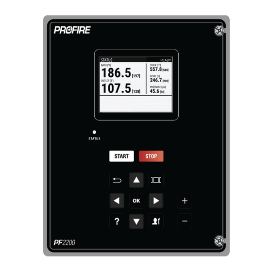
Page 58: Status Screen
STATUS SCREEN The Status screen displays various information relevant to the operation of the burner. To change the zoom level of the Status Screen, use the or keys. The linked image cannot be displayed. The file may have been moved, renamed, or deleted. Verify that the link points to the correct file and location. The linked image cannot be displayed. - Page 59 SETTINGS The settings screen contains all controller settings grouped by type for easy settings adjustment and commissioning. Operator Mode Commissioning Mode COMMISSIONING Commissioning Mode is a mode that allows read-only access to all settings within the system. Users must enter a valid password when prompted in order to enable settings modifications.
- Page 60 SETTINGS MODIFICATION Below is an example of the navigational sequence to enter the Bath Sensor type setting. This sequence is typical for all settings adjustments. In this example there is an assumption the user has entered Commissioning Mode by pressing the Commission Mode Key.
- Page 61 DROP-DOWN MENU CHANGES To make changes to a Drop-down menu option there are two methods as follows. Method One: 1. Highlight the drop-down menu you wish to change and press the key. 2. Enter the password if prompted then press and repeat step 1.
- Page 62 MENU MAPS SETTINGS MAPS Supplied for you below is a set of menu maps for each of the elements in the settings screen of the PF2200. These maps show the pathways and the options for each setting. TEMPERATURES BATH TEMPERATURE INPUT Name Default Options /...
- Page 63 Name Default Options / Description Configuration Range Notes RTD mode must be less than 850 °C. Pilot Off 85 °C 0 °C - 1350 Temperature threshold at Pilot Off Setpoint 185 °F °C which, if exceeded, the system Setpoint must 32 °F - 2462 turns off the pilot valve(s).
- Page 64 OUTLET TEMPERATURE Name Default Options / Description Configuration Range Notes Type Temperature sensing element type. Can be Type K Thermocouple (grounded or ungrounded) or PT100 RTD Mode Disabled Disabled Mode for the temperature input, At least one of Process used by the system to determine Bath Mode, Control how the input is to be used.
- Page 65 Name Default Options / Description Configuration Range Notes less than Pilot Off Setpoint. Process 80 °C 0 °C - Temperature setpoint the system Process Setpoint 176 °F 1350 °C attempts to maintain when in Setpoint must 32 °F - Process Control mode. be greater 2462 °F than Low...
- Page 66 STACK Name Default Options / Description Configuration Range Notes Type Temperature sensing element type. Can be Type K Thermocouple (grounded or ungrounded) or PT100 RTD Mode Disabled Disabled Mode for the temperature High Temp input, used by the system to determine how the input is to Display Only be used.
- Page 67 INPUTS LEVEL/FLOW Name Default Options / Description Configuration Range Notes Type Digital Disabled Level/Flow sensor type. It can Digital be configured as a switch 4-20 (digital), transmitter (4-20), or disabled. Digital Alarm Alarm Action the system takes when Type is must Mode Wait a de-energized contact occurs.
- Page 68 Name Default Options / Description Configuration Range Notes 4-20 High 19.6 mA 4 mA - 20 mA Input threshold at which, if Type is must Trip exceeded, the system initiates bet set to 4-20 a high-trip event. The 4-20 High Trip Mode setting defines the high-trip event.
- Page 69 Name Default Options / Range Description Configuration Notes 4-20 Span 206.843 0 kPa - 100000 Pressure value Span Max corresponding to 20mA must be 30 psi 0 psi - 14504 psi output from the 4-20mA greater than transmitter. Span Min and 4-20 High Trip 4-20 Low 4 mA...
- Page 70 Name Default Options / Range Description Configuration Notes Warning Main Permissive...
- Page 71 PRESSURE HIGH Name Default Options Description / Range Pressure Enabled Disabled Controls whether the High-Pressure input is enabled or High Enabled disabled. See the High-Pressure Input section for more details. AUX IN 1&2 Name Default Options / Description Configuration Range Note Type Digital...
- Page 72 Name Default Options / Description Configuration Range Note 4-20 High Alarm Alarm Action the system takes when a Type is must Trip Mode Wait high-trip event occurs. be set to 4-20 Warning Main Permissive 4-20 Low 0 – 100% Input threshold at which, if not Type is must Trip exceeded, the system initiates a...
- Page 73 Name Default Options / Description Configuration Range Note greater than Span Min...
- Page 74 PROOF OF CLOSURE Name Default Options Description Proof of Enabled Disabled Controls whether the Proof of Closure Closure Enabled input is enabled or disabled. See Proof of Closure section for more details. REMOTE START Name Default Options Description Remote Start Enabled Disabled Controls Whether the Remote Start...
- Page 75 OUTPUTS STATUS Name Default Options Description Status Contact Disabled Disabled Defines the behavior of the Mode Enabled Status Contact. VALVES Name Default Options Description Pilot Valve 10% - 100% The duty cycle of the output. The higher value corresponds to higher average output.
- Page 76 AUX 1 & 2 Name Default Options Description Mode Disabled Disabled Defines the behavior of the Level/Flow Echo Auxiliary Output. See the Aux In 1 Echo Auxiliary Outputs section for Aux In 2 Echo more details. Modbus Echo Bath Temp Echo Outlet Temp Echo Stack Temp Echo...
- Page 77 Name Default Options Description Manual Override Disabled Disabled Manual override TCV Enabled functionality, used in conjunction with Manual Position setting. See Temperature Control Valve (TCV) output section. Manual Position 0 % - 100 % Position of TCV when Manual Override is enabled. See Temperature Control Valve (TCV) output section.
- Page 78 Name Default Options Description Pilot 2 Disabled Disabled Enables the second Pilot valve Enabled output and flame detection input.
- Page 79 TIMING Name Default Options Description Purge Time 60 sec 10 sec – 900 sec The time which the system remains in the Purge state. Pilot Startup 15 sec 15 sec – 600 sec The minimum time in which the system Delay Time remains in the Pilot state when starting.
- Page 80 PID CONTROL Name Default Options Description Process 10 °C 18 °F 0 °C - 1000 °C This is the proportional Band used Proportional 0 °F - 1800 °F for the PID calculation. In cascaded Band control mode, this value applies to the bath PID loop.
- Page 81 Name Default Options Description Output Rate 100 %/sec 0.1 %/sec - 100 This is the limit for the maximum Limit %/sec output change of the TCV per second. A larger value allows for a quicker change in output. A smaller value slows down any change in output.
- Page 82 Name Default Range Description Incomplete, the system is incapable of running.
- Page 83 UNITS Name Default Range Description Temperature Units Celsius Celsius Display units for Temperature Fahrenheit inputs. Pressure Units Display units for Pressure input. inch wc oz/in2 kg/cm2 Percent Milliamps Level/Flow Units Litres Litres Display units for Level/Flow input. US Gallons L/sec L/min m3/sec m3/min...
- Page 84 MODBUS Name Default Range Description Slave Address 1 - 247 Modbus slave address of the PF2200. Baud Rate 9600 9600 Baud rate for the RS-485 link. 19200 Stop Bits The number of stop bits. Used for configuring the RS- 485 protocol. Parity None None...
-
Page 85: System Screen
The System screen contains a variety of tools and diagnostic information for customization, troubleshooting, and commissioning support. EVENT LOG The PF2200-SB event log continuously records Alarms, Warnings, Shutdowns, and Process control decisions as well as general system information and stores it on the USB storage device (if installed). -
Page 86: Data Logging
DATA LOGGING The PF2200-SB data logging tool will monitor various input and output data and will automatically log the data to the supplied USB storage device. Use the keypad to choose up to 8 items to log to the USB. The sample interval rate for data collection is 15 seconds. - Page 87 FLAME DIAGNOSTICS The Flame Diagnostics screen shows a real-time evaluation of the pilot status, and indicates whether the flame is Strong, Weak, or not present. Flame failures, and relights are also recorded for troubleshooting and maintenance scheduling. STATUS PRIORITY The Status Priority screen allows you to change how and what data is shown on the Status screen.
-
Page 88: Reset Settings
RESET SETTINGS Reset Settings allows the user to reset all settings back to the factory defaults. When this action is taken, the user will be prompted to confirm the intention to reset all settings to defaults. BACKUP / RESTORE SETTINGS BMS settings may be saved to a USB backup. -
Page 89: Firmware Update
If the UI and the BMS version do not match a warning will be displayed on the UI. To update the firmware, follow the steps below: 1. Save the firmware bundle supplied by Profire to the supplied USB storage device. 2. Ensure it is safe to open the enclosure. - Page 90 7. The contents of the USB storage device will be displayed. Select the desired firmware bundle and press the key. 8. Confirm bundle selection. 9. Select whether to update UI only or both UI and BMS together and press...
- Page 91 10. The system will update the software and restart the unit. 11. To confirm the update is successful, navigate to the System screen and select the About menu item. Confirm the new firmware and UI software versions are correct.
-
Page 92: Troubleshooting
TROUBLESHOOTING For a complete list of , refer to the PF2200 ALERT CODES. Alerts and there meaning Problem Diagnosis The System has visible flame but cannot Ensure pilot assembly, flame rod, and the detect gap between are fully engulfed in flame. If not, adjust rod position Ensure flame detection wiring does not exceed the recommended maximum. - Page 93 Problem Diagnosis measurement should be done with the BMS card powered off. If properly wired, the multi-meter should read a resistance of the solenoid coil plus the run length (i.e. if the multimeter reads open, there is likely a problem with wiring). Ensure the PWM setting is correct for the appropriate solenoid.
-
Page 94: Maintenance
MAINTENANCE During maintenance, with respect to software and setup, a visual inspection should be done to determine the following: • What is the firmware version being used? What are the appliance specific settings? An example list of settings can be found •... -
Page 95: Repair And Replacement
I/O separately and verifying the PF2200 annunciates the appropriate alarm. REPAIR and REPLACEMENT Profire Energy does not support on-site repairs for cards. For replacement cards, contact Profire Energy customer service. In the event replacement card(s) are used, care must be taken to ensure proper firmware is loaded on both the User Interface and BMS cards. - Page 96 PROFIRE CONTACT INFORMATION If you have any concerns or questions about this product, please contact PROFIRE as follows: United States Canada 1.801.796.5127 1.780.960.5278 321 South, 1250 West Suite 1 9671 - 283 Street Acheson Lindon, UT Edmonton, AB 84042, USA T7X 6J6, Canada support@profireenergy.com...
Need help?
Do you have a question about the PF2200-SB and is the answer not in the manual?
Questions and answers