ProFire PF2200-SB User Manual
Hide thumbs
Also See for PF2200-SB:
- Product manual (98 pages) ,
- Installation manual (40 pages) ,
- Product manual (85 pages)
Table of Contents
Advertisement
Advertisement
Table of Contents

Related Manuals for ProFire PF2200-SB


Summary of Contents for ProFire PF2200-SB
- Page 1 PF2200-SB USER GUIDE...
-
Page 2: Table Of Contents
TABLE OF CONTENTS OVERVIEW ............................... 3 STATUS LED ................................3 STARTING/STOPPING ..............................4 NAVIGATION................................4 MENU MAP ................................. 5 STATUS SCREEN ................................6 OPERATIONAL STATES ............................7 POWER ON STATE ............................... 7 LOCKOUT STATE ................................. 7 ALARM STATE ................................8 READY STATE ................................ -
Page 3: Overview
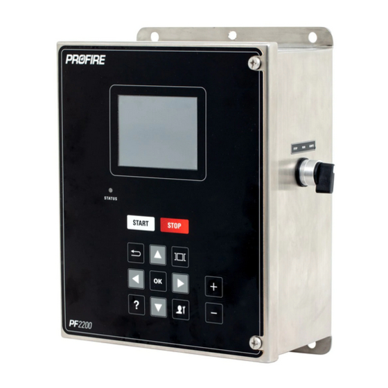
OVERVIEW This User Guide is intended to help the Operator use the PF2200-SB Burner Management System. The keypad located on the front of the unit is the primary method for the operator to interface with the PF2200 system. It allows for screen navigation, starting and stopping the burner, as well as allowing commissioning and adjusting the PF2200 system. -
Page 4: Starting/Stopping
Energy. Note: Holding the switch in the Ignite position for more than 4.5 seconds results in a system shutdown on an External Stuck Switch event. NAVIGATION See the PF2200-SB Installation Manual for more information on the commissioning of the PF2200-SB. -
Page 5: Menu Map
MENU MAP Note: The above diagram shows the menu map of the PF2200 in User Mode. This mode has a limited menu item and options capability. -
Page 6: Status Screen
STATUS SCREEN The Status screen can show different • layouts based on a set of priorities that can be customized in the System screen under the Status Priority menu item. To switch through the different status • screen layouts, use the Plus and Minus keys while in operation. -
Page 7: Operational States
OPERATIONAL STATES This section describes the different states of the PF2200-SB and outlines the behavior of the system in each state. POWER ON STATE Power On is the default state of the system when power is applied. If a previous lockout condition is present, the system transitions into the lockout state. -
Page 8: Alarm State
In the Lockout state, the status of each powered outputs is as follows: Powered Output Status Pilot 1 / 2 De-energized Coil 1 / 2 De-energized De-energized De-energized For more information on Modbus Register commands, refer to Modbus Registers. ALARM STATE indicative of a static problem (e.g., - transmitter not connected, system voltage too low, etc.). -
Page 9: Waiting State
In this system state, the status of each powered output is as follows: Powered Output Status Pilot 1 De-energized during Pre-Ignition Pilot 2 De-energized if disabled Same as Pilot 1 if enabled Coil 1 De-energized during startup delay Coil 2 De-energized if disabled Same as Coil 1 if enabled De-energized... -
Page 10: Ignition State
IGNITION STATE Ignition is the state where a pilot flame is established, and the system achieves this by energizing the coil and pilot outputs while monitoring flame presence on the ionization inputs. If a flame is not detected within the pilot-flame establishing period of 4 seconds, the system purges and restarts the ignition sequence. -
Page 11: Pilot State
PILOT STATE The Pilot state is the system state which represents a minimum amount of heating required to light off the main burner. It is typically tied to the Pilot valve in the fuel gas train – meaning that the pilot valve(s) are on in this state but, the main valves are off. -
Page 12: Process Control State
Energized or De-energized, depending on the process control state. See process control modes below for specific valve behavior. For more information on the different operational sates of the PF2200-SB see the Operational States section found in the Product Manual here. For more information on setting up a PID see the... -
Page 13: Settings
TEMPERATURE INPUTS The PF2200-SB has three distinct temperature inputs: Bath, Outlet, and Stack; each of which is configurable to be either a Type-K thermocouple or PT-100 RTD input. The following is a description of each of the setpoints and available setpoints for each Input: High-Temperature ESD Setpoint: the temperature at which the system shuts down. -
Page 14: Flame Detection I/O (Ion +/-)
Through the use of the rectification property of the flame, the PF2200-SB measures the presence of a flame by applying an AC signal to the rod. If an open circuit event exists, the result is Loss of Flame. -
Page 15: Emergency Shutdown Input
/ PLC output (digital) or transmitter (4-20mA). The Auxiliary Inputs have trip modes of Alarm, Wait, Warning, and Main Permissive. For information on all the various Inputs and outputs of the PF2200-SB visit the Inputs Outputs sections of the Product Manual. -
Page 16: System Screen
DATA LOGGING SCREEN The PF2200-SB data logging tool will monitor various input and output data and will automatically log the data to the supplied USB storage device. Use the keypad to choose up to 8 items to log to the USB. The sample interval rate for data collection is... -
Page 17: System Diagnostics Screen
that can be opened and inspected. when the USB storage device becomes full the logging will begin to delete the oldest logs to make room for the newest logs recorded. The statistics dialog will show an approximation of logging time remaining on the USB before old logs start getting deleted. -
Page 18: Flame Diagnostics Screen
FLAME DIAGNOSTICS SCREEN Under the Flame Diagnostics screen, the Flame Strength and Diagnostic Voltage are displayed. This screen also records the number of Flame Fails and Relights. On the right portion of the screen, you are shown a graphical representation of the flame quality. STATUS PRIORITY SCREEN The Status Priority screen allows the user to adjust the status screens in accordance to the desired information for the application of the system. -
Page 19: Reset/Backup/Restore Settings
PF2200-SB Manual for more information on the Systems screen. FIRMWARE UPDATE The Firmware update function can be used to update the system with approved Profire Firmware Bundles. Refer to the Firmware Update Guide for more information on the Firmware Update process. - Page 20 Problem Diagnosis 3. If firmware update fails, card is likely faulty. The Ignition transformer “clicks” but no 1. Ensure all wires in the ignition path are properly visible spark terminated and that there is a low impedance path from the primary-windings to the BMS card as well as the secondary- windings to the ignition rod.
Need help?
Do you have a question about the PF2200-SB and is the answer not in the manual?
Questions and answers