ProFire PF2100 User Manual
Hide thumbs
Also See for PF2100:
- Troubleshooting manual (1 page) ,
- Programming manual (7 pages) ,
- Replacement manual (3 pages)
Table of Contents
Advertisement
Advertisement
Table of Contents
Troubleshooting

Related Manuals for ProFire PF2100


Summary of Contents for ProFire PF2100
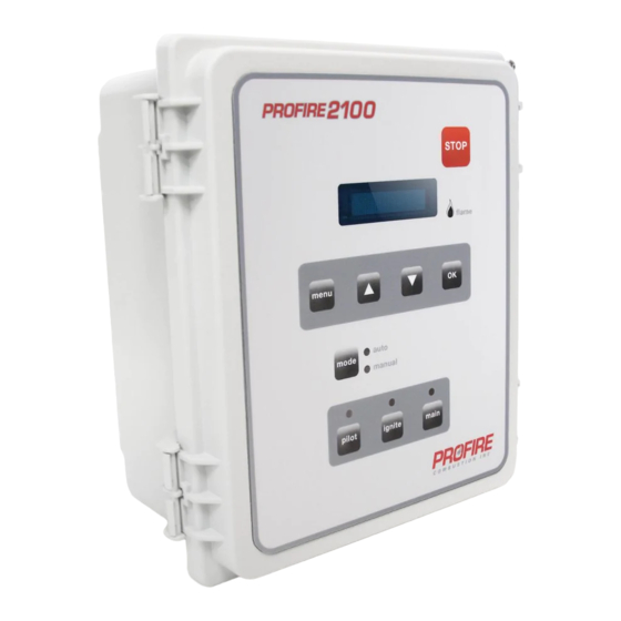
- Page 1 PF 2100 USER MANUAL For Firmware E1.8.217 Rev. 1.0...
-
Page 2: Table Of Contents
TABLE OF CONTENTS For Firmware E1.8.217 Rev. 1.0 PF2100 MANUAL 1 INTRODUCTION 4 SYSTEM BEHAVIOR 1.1 Important Safety Information 4.1 System Behavior 1.2 HW & FW Versioning 4.2 Process Control 1.3 Approvals 4.3 Contact Behavior 1.4 Available Models 1.5 Included Components 5 EXPANSION CARDS 1.6 Common Applications &... -
Page 3: Introduction
1 | INTRODUCTION 1.2 | HW & FW Versioning This version of the manual was written for use with PF2100 systems that have the following hardware The PF2100 BMS (Burner Management System) is an electronic control and monitoring system designed and firmware versions. -
Page 4: Included Components
Transient protected and fail-safe circuits CODE DESCRIPTION E0000 E0400 E0M00 E04M0 EC000 EC400 ECM00 EC4M0 All solid state circuit components PF2100 • • • • • • • • CSA compliant for Class I, Division 2 locations Mounting Brackets & Screws •... -
Page 5: Common Applications & Optional Hardware
External Ignition Coil 1.6 | Common Applications & Optional Hardware Please contact Profire Sales for further information. Below are examples of some of the many applications that the PF2100 can be used in. Line Heater Tank Heater Gas Production Unit... -
Page 6: Terminal Card Descriptions
HW SERIAL / VERSION LABEL FW VERSION LABEL KEYPAD FLEX CABLE RIBBON CABLE TERMINAL EXPECTED CONNECTIONS DESCRIPTION (door to terminal) High Fire/Main + High Fire / Main Valve positive terminal Solenoid valves must be connected between MODBUS or DATALOGGING CARD the “+”... -
Page 7: Installation
Dry contact switch is expected. The input Start + Remote start input from an external device. ie. complete the installation process. If you are new to the PF2100, you should read this whole section and PLC. is internally pulled up to 9VDC via a 3.75kΩ... -
Page 8: Mounting Considerations
4. In locations that may be prone to flooding. 2.2 | Mounting Considerations The PF2100 is typically mounted near the burner it is controlling or in another location that is both safe and easily accessible. The recommended mounting height is 1.5m (5ft) above the ground or platform for CONDUIT AND CABLE CONSIDERATIONS the comfort of the operators. -
Page 9: Terminal Card Diagram
NOTE: If you have not wired a PF2100 system, please refer to the PF 2100 Install Guide for detailed All thermocouples are cold junction compensated. For this reason, it is important to make sure that wiring instructions. - Page 10 When wiring the ignition and flame detection circuits, the wire length must be carefully There are 6 dry contact inputs on the PF2100. The expected connection to each of these is a switch. considered. If the wire lengths are too long, the PF2100 may not be able to deliver enough These contacts must all be closed (shorted) in order for the system to start.
- Page 11 Note that there are three possible ways to wire the ignition coil and flame detection circuit Straight Coil Coil 1/8” to 1/4” Silicone with the PF2100 as illustrated in the table. Single Boot Ferrule CONFIGURATION (COIL TYPE) SINGLE ROD DUAL ROD Internal Coil •...
- Page 12 Burner Housing Screw Using Extra Rods to Improve Flame Detection PF2100 Pluggable In some challenging installations such as non-enclosed or high velocity burners, adding one Header P6 or two additional rods may be necessary. A second flame detection rod can help in cases...
-
Page 13: User Interface & Settings
3. A keypad DISPLAY KEYS The screen on the PF2100 displays two lines of text which are used to show system status, warnings, Stop Key alarms, prompts, and menus. It is illuminated for ease of reading in both bright sunlight and darkness. -
Page 14: Menu Navigation
3.2 | Menu Navigation The software user interface is shown on the PF2100 display. While the system is powered, the state of the system is displayed on the screen. The user can also change settings via this interface. Below is a diagram showing the various types of information that can be accessed through the interface. -
Page 15: Menu Map
FIRMWARE VERSION SCREEN AVAILABLE FEATURES WITHIN OPERATIONAL MODES The Firmware Version Screen shows the firmware version of all cards in the system including the Door Card, Terminal Card, and any installed Expansion Cards. MODE DISPLAY MENUS REVIEW SETPOINT ADJUST Manual System State Process Temperature WARNING MESSAGES... - Page 16 4-20 High Level PID – Proportional Commission Date Level ESDs Location Setpoint Band Entry 4-20 Low Level Commission Location PID – Integral Thermocouple Errors Setpoint Entry Rest to Factory 4-20 Pressure Setpoint PID – Derivative Terminal Errors Defaults 4-20 Low Pressure System Errors Setpoint Flame...
- Page 17 CONTROL SETUP (MENU 5) Control State Control State Debug Information Hidden This menu contains various optional Process Control settings. It cannot be accessed while the PF2100 is Terminal Card State Term Card Debug Information Hidden running. MENU MAP...
-
Page 18: Initial System Settings
MENU MAP ON SCREEN BRIEF DESCRIPTION RANGE DEFAULT SETTING MENU MAP ON SCREEN BRIEF DESCRIPTION 4-20 Output Mode 4-20 Out Mode Configures 4-20 Output mode Valve Control 1 Disabled 4-20 Low Level Setpoint Level below which the system will shutdown or wait if Level Event Restart is Valve Control 2, enabled Temp Output... - Page 19 PLC, controlling the process. The The PF2100 is designed to operate with a nominal 12VDC or 24VDC Power Supply. The system will not PLC would turn the system on and off using the Start contacts. This behaviour can still be be damaged by applying any voltage in or near this range regardless of menu settings.
-
Page 20: Optional Settings
PID Controller section. The Valve Controls use a traditional safety solenoid valve connected to the PF2100’s Low Fire Process Setpoint (Menu 1) outputs. The Low Fire setting must also be enabled by setting it to “On at Proc Setpoint. ”... - Page 21 Alarm Mode (Menu 4) This is the location where the PF2100 was installed. Use the Up and Down keys to edit each character and OK to advance to the next character. The Alarm Mode is used to select whether the Status Contact will open when the unit is stopped remotely via the Start Contact.
- Page 22 RESTART SETTINGS The system is started by a user by switching to Auto Mode. The PF2100 can be configured to automatically restart after certain alarm conditions clear. The number of The system is started remotely via the Start Contact. restart attempts is configurable. There are three settings that affect restart behavior: Auto Restart, Level The Pilot Turns off as a result of process control and then is Event Restart, and Restart Attempts.
-
Page 23: System Operation
3.6 | System Operation Low-To-High Fire Delay (Menu 5) This setting is used to set the minimum amount of time that must elapse between the low fire valve opening and the high fire valve opening. This setting is only available if Low This section includes information about how to start and stop the system, how to review key system Fire is enabled in menu 5. - Page 24 Automatic Restarts condition is removed and the fault is acknowledged. Shutdown condition examples include the Process Temperature rising above the High Temp ESD Setpoint, the High Pressure If the Auto Restart feature is enabled, the system will attempt to automatically start after a Contact Opening, the ESD Contact Opening, etc.
- Page 25 (#32) is the oldest. MODE HOME SCREEN QUICK SETPOINT CHANGE REVIEW MENU SYSTEM MENUS AVAILABLE AVAILABLE AVAILABLE When the log is full, the oldest event is removed from the list to make room for the next newest event. Navigate through the log using the up and down arrow keys. Press OK to Manual Mode, System State 1-6 (and sometimes 7)
-
Page 26: System Behavior
PF2100 changes states while in Auto mode, the new state will be shown momentarily on the display. In Manual Mode, the current state is always shown on the display. -
Page 27: Process Control
1. The Main Valve opens and the Process Temperature increases. 2. The Process Temperature exceeds Process Setpoint, the Main The PF2100 has three inputs: High Temp, Proc Temp, and Aux Temp. By default, these signals correspond Valve closes, and the Process Temperature begins to drop. - Page 28 The system behaves the same as in the standard process control diagram until the demand for heat 1. The Process Temperature continues to rise. drops. 2. The Process Temperature exceeds the High Fire Setpoint, the High Fire Valve closes, and the Process Temperature continues ˚C TIME ˚F...
-
Page 29: Contact Behavior
After the system has been initially started, if it needs to be automatically relit, the system responds sudden emptying of a tank heater. based on the reason the pilot is off. If the event is a controlled one, the PF2100 follows the Process 2. The Process Temp rises sharply. - Page 30 ESD INPUT contact will remain closed. The ESD Input Contact is used to stop the PF2100 in the event of an emergency. This is normally done by 5. While Restarting: If the flame blows out and the system is connecting the contact to the site’s ESD Loop. The PF2100 will shutdown immediately when the contact in the process of relighting the pilot, the status contact will is opened and cannot be restarted until the contact is closed.
- Page 31 Level Input Contact on the PF2100. If the fluid level drops below the switch position, the switch opens and the PF2100 will stop heating the tank. This is to prevent damage to the tank and fire tube which may result from applying heat to the empty tank. Generally, this situation arises when a CHART 2 EVENTS tanker truck arrives on site and empties the tank into the truck.
-
Page 32: Expansion Cards
OPEN This can be used as an alternative to the Level Contact which is built into the PF2100. This input can be wired to a 4-20mA Level Transmitter to obtain an actual reading of the tank level. The transmitter range CLOSED and units can be set along with low and high level thresholds. - Page 33 4-20MA REPEATER EXPANSION CARD SETTINGS Input These settings all apply to the 4-20mA Repeater Expansion Card which must be installed in the PF2100’s 2. Enable the Level DIP Switch on the 4-20 Card expansion slot. These settings can all be found in Menu 6. Some of these settings will be hidden if the 3.
- Page 34 HIGH LEVEL OUTPUT CONTACTS high pressure setpoint. This is to allow for easy recovery from the common issue of leaky regulators. If the regulator upstream from the high pressure switch is leaky, it can allow pressure to accumulate EVENT 5 6 7 at the switch’s position over time while the system is not running.
- Page 35 4-20 PRESSURE INPUT CHART 3 EVENTS EVENT System started by user with pressure above high setpoint due to a slow leak in the regulator. Pressure begins to drop slowly through pilot valve. 20mA Main valve opens and pressure begins to drop faster through main valves. PRESSURE HIGH SP The pressure drops below the high setpoint within 2s of the main valves opening and the system continues running.
-
Page 36: Modbus Expansion Card
In this case, wire the PF2100’s 4-20mA Output to a PLC’s 4-20mA Input. Note that values 0x01 to 0xFE. the PF2100 provides the loop power. The PLC resistance is expected to be in the range of 120 Ohms and 250 Ohms. -
Page 37: Troubleshooting
2. Check that the system has the latest firmware. Firmware older than v1.8.005 was prone to shutdown on transient voltage This section is designed to help you troubleshoot the PF2100. A list of common issues and solutions, spikes and dips. -
Page 38: Shutdown Messages
Status Contact Opens but System Continues To Run The following is a list of messages that may flash on the PF2100 display after the system has shutdown. Typically, the word “SHUTDOWN” in large text will flash alternately with one of the messages below. - Page 39 ON SCREEN DESCRIPTION POSSIBLE SOLUTIONS ON SCREEN DESCRIPTION POSSIBLE SOLUTIONS Comparison: The Door Card and Terminal Card do not Remove level contact wiring and jumper the Flame detected before start Flame was detected prior to the system This may indicate a leaky valve, inadequate purge LVL DC:xxx TC:xxx agree on the state of the Level Contact.
-
Page 40: Alarm Codes
The Door Card and Terminal Card do not Reset to factory defaults. The following is a list of alarm codes that may show on the Alarm screen of the PF2100 display. These agree on the value of the Purge Time Setting. -
Page 41: Warning Messages
Verify proper settings and check wiring. 4-20mA Expansion Card’s Level Input The following is a list of warning messages that may flash periodically on the PF2100 display. These is reading a value below the 4-20 Level messages indicate a problem that may be developing or a condition from which the system may Low Setpoint. -
Page 42: Flame Detection Troubleshooting Guide
ION - terminals? Make sure that there is a metal-on-metal connection from the pilot noz- zle to the housing and a ground wire from the housing to the PF2100. Make sure that the ignition rod is fully immersed in the flame. -
Page 43: Thermocouple Troubleshooting Guide
6.6 | Thermocouple Troubleshooting Guide Flow Chart 2 Problem with Thermocouples. Set the Multimeter to measure DC voltage across ION + and ION - with the system in manual mode. Is the reading across ION + and ION - around +5VDC? Make sure that both the High Temp and Pro- cess thermocouples are connected. -
Page 44: Appendices
If the temperature control is unstable or if faster control response is needed, the following The PF2100 uses a two-point calibration system to provide readings with greater accuracy than a single- procedure can be followed to adjust the PID settings. This procedure is not a comprehensive method for point offset calibration. - Page 45 For the 4-20mA Output, the first calibration point is 4mA and the second calibration point is 20mA. You 15. Use the Up and Down Keys to adjust the temperature displayed on the PF2100 to match the temperature being will need a handheld process calibrator such as the Fluke 725.
- Page 46 MENU 7 2. Use the Up or Down key to select “Yes” and begin the CALIBRATION ( calibration process. The display will now read “Apply 4mA This menu is used to adjust the calibration of thermocouples, 4-20mA Output, and 4-20mA Expansion then press OK”...
-
Page 47: C Resetting To Defaults
Also note that all settings are stored on the Door Card. If the Door Card is replaced for any reason, the settings will need to be re-entered and calibration may need to be performed. FOR ANY QUESTIONS PLEASE VISIT OR CALL US. www.profireenergy.com | 1.855.PRO.FIRE www.profireenergy.com © 2015 PROFIRE...
Need help?
Do you have a question about the PF2100 and is the answer not in the manual?
Questions and answers