
Related Manuals for Image Engineering LED-Panel V4


Summary of Contents for Image Engineering LED-Panel V4
- Page 1 LED-Panel V4 User Manual 27. March 2020 Image Engineering GmbH & Co. KG · Im Gleisdreieck 5 · 50169 Kerpen-Horrem · Germany T +49 2273 99991 - 0 · F +49 2273 99991 -10 · www.image-engineering.com...
-
Page 2: Table Of Contents
5.5.1 File list........................19 5.5.2 Control panel ......................19 Analysis ..........................20 LED-Panel ........................20 iQ-Trigger ......................... 21 5.5.3 Image view ......................22 5.5.4 Meta data ......................22 5.5.5 Results ........................23 Image Engineering LED-Panel V4 Seite 2 von 44... - Page 3 Trigger iQ-Defocus (LED-Panel V4 only)............41 6.2.29 Set auto release (LED-Panel V4 only) ............. 41 6.2.30 Set post roll time (LED-Panel V4 only) ............42 ADDITIONAL INFORMATION ..................43 7.1 Disposal instructions....................43 TECHNICAL DATA SHEET ....................43 Image Engineering...
- Page 4 TRADEMARK AND COPYRIGHT ..................44 9.1 Trademarks ........................44 9.2 Software by Third Parties .................... 44 9.3 Copyright Information ....................44 Image Engineering LED-Panel V4 Seite 4 von 44...
-
Page 5: Introduction
Keep these instructions in a safe place and pass them to any future user. 1.1 Intended use LED-Panel V4 is designed to perform timing measurements on digital cameras. With iQ-LED- Panel V4 measurements according to ISO 15739 can beperformed. •... -
Page 6: Foreseeable Missuse
Getting started 1.2 Foreseeable missuse 1.2.1 Older LED-Panel verisons Most parts of this manual apply to LED-Panel V4. Please contact Image Engineering for the manual for a previous version of LED-Panel. 1.3 General safety information Do not open the device without any instructions from the Image Engineering support and when connected to the power supply. -
Page 7: Operating Instructions Hardware
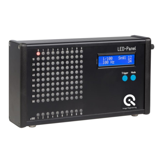
3 OPERATING INSTRUCTIONS HARDWARE 3.1 Set up hardware Connect the power cord to the power supply on the side of LED-Panel V4. Connect the power supply to electricity. Switch on LED-Panel V4 by setting the power switch to “I”. The power switch is located beside the power supply. -
Page 8: Trigger Mode
The LED-Panel V4 can be operated manually or via software (USB interface). The downside of using USB with the LED-Panel V4 is that due to controller limitations the maximum speed is limited to 200 μs (5 kHz). Therefore the device provides a switch that allows switching the USB connection on and off. -
Page 9: Setting Mode And Time
Operating instructions hardware 3.2.2 Setting mode and time Mode response time exposure time frame rate roll. shutter Measurement Response Time Exposure Time Frame Rate Rolling Shutter Single LED Single LED Bottom row: Entire row/column moves across moves across single LED moves across LED Movement matrix according... -
Page 10: Display Brightness
Operating instructions hardware Display Brightness The brightness of the display can be modified by using the rotary knob. Press and hold the rotary knob until the message "Back light" and" XX %"will be shown on the display. Turn the rotary knob to change the back light intensity. -
Page 11: Measurement Methods
Measurement methods 4 MEASUREMENT METHODS Depending on operating mode, following measurements can be made with the aid of the LED- Panel: 1. Shutter lag without autofocus time 2. Shutter lag with autofocus time 3. Exposure times 4. Video recording rate / Framerate 5. -
Page 12: Shutter Lag With Autofocus Time
Measurement methods Example LED-Panel settings: Operating mode TRIGGER EXT Exposure time (1/x s) 1/10 s LED No. 2 is lit up (Figure 2): Shutter lag is 0.2 seconds (2 * 1/10 s) 4.2 Shutter lag with autofocus time The LED-Panel is used in TRIGGER EXT operating mode and a micro switch is connected. Two pictures are taken and the shutter lag is calculated. -
Page 13: Exposure Time
Measurement methods Example LED-Panel settings: Operating mode TRIGGER EXT Exposure time (1/x s) 1/10 sec Shutter lag without autofocus time: LED No. 2 lights up → 0.2 s Shutter lag with autofocus time: LED No. 32 lights up → 3.2 s Autofocus time = 3.2 s - 0.2 s = 3 s 4.3 Exposure Time Exposure times of cameras can be measured with the aid of the LED-Panel. -
Page 14: Speed Of Multi Shot Mode
Measurement methods Figure 6 Figure 5 The frequency of the LED-Panel does not match The frequency of the LED-Panel matches the the frame rate of the camera (flickering LEDs) frame rate of the camera (LEDs glow permanently) 4.5 Speed of multi shot mode The speed of the multi shot mode of cameras can also be measured with the aid of the LED- Panel. -
Page 15: Rolling Shutter Speed
Measurement methods Example Camera exposure time: 1/250 s LED-Panel settings: CONTINUOUS, exposure time 1/10 s Each time the LED has moved three places forwards between the consecutive images. With LED-Panel’s frequency set to 0.1s this means the multi shot mode has the speed of 0.3 s per picture (i.e. - Page 16 Measurement methods For software based rolling shutter analysis we recommend two LED-Panels in “Exposure Time” mode, one in the top left corner and one in the bottom right corner. For detailed information on how to set up two LED-Panels with you device under test, please see the following two infographics.
-
Page 17: Operating Instructions Software
C:\Users\John_Doe\AppData\Roaming\Image Engineering) to store application settings. 5.3 Set up hardware and software for software control Connect the power cord to the power supply on the side of LED-Panel V4. Connect the power supply to electricity. Connect the USB cable to the LED-Panel V4 and to your PC. Switch on LED-Panel V4 by setting the power switch to “I”. -
Page 18: Software Description
TIFF and BMP. The results of the analysis can be saved as plain text (*.txt) and/or XML file for further processing. Note: Software based analysis is only available for LED-Panel V4 Figure 15 The graphical user interface (GUI) is divided into three major parts (see Figure 15) •... -
Page 19: File List
MODE button and hold it, then switch on the power. 5.5.1 File list The file list is located on the top left side of the GUI. Add your images taken from LED-Panel V4 to the list. The file list can contain different file types such as JPEG, PNG, TIFF and BMP. -
Page 20: Analysis
Operating instructions software Analysis The “Analysis” tab contains the general settings. “LED-Panel” and “iQ-Trigger” tabs are used to control connected devices. Figure 17 In the “Analysis tab” (Figure 17) you can choose the measurement method and the frequency. The set frequency is used to calculate the time shown by the LED-Panel in your images. For further details on how to measure different camera timings please refer to chapter 5 and ISO 15781. -
Page 21: Iq-Trigger
Operating instructions software The slider Display brightness adjusts the display brightness. This might be helpful to adjust the exposure time of the camera correctly for specific testing conditions. For example if you perform test under low light conditions and use the automatic exposure mode of your camera. Without dimming the display of LED-Panel the bright display light can influence the exposure of your camera. -
Page 22: Image View
Operating instructions software glowing LED in the image represents the negative shooting or shutter release time lag. Defocus time: time period between triggering the defocus and start of LED-Panel and iQ-Trigger Sequence: time period between iterations Iterations: defining the amount of release iterations Release time: determines how long the camera release button will be pressed by iQ-Trigger, value ranges from 0.1s to 25s... -
Page 23: Results
Operating instructions software 5.5.5 Results The results panel (Figure 22) shows analysis results as a hierarchical tree with two columns, “Name” and “Time [s]”. The first column shows the measurements with the assigned images. For each image the detected LED- Panels and measurement types are listed. -
Page 24: Export Results
Operating instructions software 5.5.7 Export results Figure 24 The export dialog lets you configure the file type to be used for the export of results. You can select • text file (*.txt), formatted for copy-and-paste into a spreadsheet • XML file (*.xml) for further processing in your workflow or both. For each measurement in the file list a result file will be written to the export folder using the given file name prefix and the current date as a suffix (fileName_YYYY-MM-DD.ext). - Page 25 Operating instructions software Figure 25 After the images are loaded into the file list make sure that the settings in the analysis tab match the settings of the LED-Panel in the images. To start the analysis, please click the Start button under the control panel.
- Page 26 Operating instructions software Figure 26 The plot tab ① shows statistics of the different measurements like mean value, fastest time, slowest time and standard deviation. Additionaly a bar plot visualize the calculated results. By check or uncheck the checkbock in the results tree ② you can display your favored plot ③...
-
Page 27: Command Line Interface (Cli)
Command Line Interface (CLI) 6 COMMAND LINE INTERFACE (CLI) 6.1 Introduction This documentation provides help on the implemented command-line functions of the LED- Panel and is intended to assist in scripting of the control software on Microsoft Windows. These instructions generally apply to LED-Panels V3 and V4, which must be connected to a PC via USB. -
Page 28: Operation Functions
Command Line Interface (CLI) 6.2 Operation Functions 6.2.1 Set Operation Mode Function setMode <mode> Description “LED-Panel.exe -setMode <mode>” sets the operation mode Parameters <mode> Description Response time measurement [xx.x μs/ms/s] Exposure time measurement [1/x s] Frame rate measurement [Hz] Rolling shutter mode All LEDs on Example LED-Panel.exe -setMode 2... -
Page 29: Set Trigger Mode
Command Line Interface (CLI) Return parameters Return value Description Response time measurement Exposure time measurement Frame rate measurement Rolling shutter mode All LEDs on Example LED-Panel.exe -getMode After the execution of this command the device will return the numerical value of the activated operation mode. -
Page 30: Get Trigger Mode
Command Line Interface (CLI) 6.2.4 Get Trigger Mode Function getTriggerMode Description “LED-Panel.exe -getTriggerMode” returns the current trigger mode Return parameters Return value Description internal (continuous) trigger external (single) trigger Example LED-Panel.exe -getTriggerMode After the execution of the command the device will return the numerical value of the activated trigger mode. -
Page 31: Get Leds Switching Time
Command Line Interface (CLI) 6.2.6 Get LEDs Switching Time Function getTime Description With the function “LED-Panel.exe -getTime” it is possible to read the switching time of the device. Return parameters After the execution of the command “LED-Panel.exe -getTime” the device will return the cycle duration in seconds or the index of the set time in case of exposure mode. -
Page 32: Reset Measurement
Command Line Interface (CLI) Function “LED-Panel.exe -isRunning” checks if the measurement is currently running. Return parameters Return value Description the device is stopped a measurement is running Table 1 Example LED-Panel.exe –isRunning After the execution of the command the device will return the value 0 or 1 representing the current measurement state. -
Page 33: Get Stop Trigger Input State
Command Line Interface (CLI) Return parameters Return value Description digital input „Camera Trigger“ is not activated digital input „Camera Trigger“ is activated Table 2 6.2.12 Get Stop Trigger Input State Function getStopTrigger Description “LED-Panel.exe -getStopTrigger” returns the state of the digital input “Stop Trigger”. Return parameters Return value Description... -
Page 34: Put The Led-Panel In Sleep Mode, Wake From Sleep Mode
Command Line Interface (CLI) Examples Return value 65 means that no LEDs are lighted in the lower LED row and the LED number 65 is lighted in the square field. There have been 65 switching periods in total. Return value 623 means that the LED number 6 is lighted in the lower LED row and the LED number 23 is lighted in the square field. -
Page 35: Get The Enabled / Disabled State Of The External Input "Camera Trigger
Command Line Interface (CLI) Example LED-Panel.exe -setCameraTrigger 0 After the execution of this command the external input “Camera Trigger” will be disabled 6.2.16 Get the Enabled / Disabled State of the external input “Camera Trigger” Function getCameraTrigger Description After the execution of the command “LED-Panel.exe -getCameraTrigger” the device returns the current activation state of the external input “Camera Trigger”. -
Page 36: Get The Enabled / Disabled State Of The External Input "Stop Trigger
Command Line Interface (CLI) LED-Panel.exe -setStopTrigger 1 After the execution of this command the external input “Stop Trigger” will be enabled. 6.2.18 Get the Enabled / Disabled State of the external input “Stop Trigger” Function getStopTrigger Description After the execution of the command “LED-Panel.exe -getStopTrigger” the device returns the current activation state of the external input “Stop Trigger”. -
Page 37: Set The Direction Of The Leds For "Response Time" And "Exposure Time" Modes
Command Line Interface (CLI) With the function “LED-Panel.exe -getDisplayBrightness” it is possible to read the intensity of the backlight illumination of the LCD display. Return Parameters After the execution of the function “LED-Panel.exe -getDisplayBrightness” the device will return a one-, two- or three-digits value of the backlight intensity in %. For instance: Return value 27 means that the intensity of the backlight is 27%. -
Page 38: Get The Direction Of The Leds For "Response Time" And "Exposure Time" Modes
Command Line Interface (CLI) 6.2.22 Get the Direction of the LEDs for “Response Time” and “Exposure Time” Modes Function getDirectionSingle Description The function “LED-Panel.exe -getDirectionSingle” returns the current moving direction of the LEDs in the “Response Time” and “Exposure Time” modes. Return values After the execution of this function the device will return a one-digit value of the current LED direction. -
Page 39: Set Leds Switching Time For The "Exposure Time" Mode
Command Line Interface (CLI) Return values After the execution of this function the device will return a one-digit value of the current direction of the LED columns. For the list of the possible return values please refer to the Table 2. 6.2.25 Set LEDs switching time for the “Exposure Time”... -
Page 40: Get Leds Switching Time For The "Exposure Time" Mode
XX of the switching time, where XX is the value of the switching time from the Table 3. For instance: Return value 17 means that the switching time is 1/3200s. 6.2.27 Trigger iQ-Trigger (LED-Panel V4 only) Function setTrigger Description If a iQ-Trigger is connected to the LED-Panel it can be triggered by using „LED-Panel -... -
Page 41: Trigger Iq-Defocus (Led-Panel V4 Only)
If a iQ-Defocus is connected to the LED-Panel it can be triggered by using „LED-Panel - setDefocus <mode> -setDefocus <duration>“. For parameters see Fehler! Verweisquelle konnte nicht gefunden werden. Fehler! Ve rweisquelle konnte nicht gefunden werden.. 6.2.29 Set auto release (LED-Panel V4 only) Function setAutoRelease Description Modern camera systems especially mobile phones often take continously photos in the background to avoid shooting time lag and provide some convenience features. -
Page 42: Set Post Roll Time (Led-Panel V4 Only)
Command Line Interface (CLI) 6.2.30 Set post roll time (LED-Panel V4 only) Function setPostRollTime Description The LED-Panel keeps running for a certain time after the iQ-Trigger was triggered by using „LED-Panel -setPostRollTime <duration>“. Value [0..30000ms] Example: LED-Panel –setPostRollTime 2000... -
Page 43: Additional Information
LED-Panel. Observe your national regulations. Make sure that the LED-Panel cannot be used by third parties after disposing of it. Contact Image Engineering if assistance for disposal is required. 8 TECHNICAL DATA SHEET See annex for the technical data sheet. It can be downloaded at the website of Image... - Page 44 INTERRUPTION OF SERVICE, LOSS OF PROFITS OR GOOD WILL, LEGAL ACTION OR ANY OTHER CONSEQUENTIAL DAMAGES. THE USER ASSUMES ALL RESPONSIBILITY ARISING FROM THE USE OF THIS SOFTWARE, FOR WHICH IMAGE ENGINEERING GMBH & CO. KG SHALL HAVE NO LIABILITY, REGARDLESS OF WHETHER SUCH USE IS LAWFUL OR FORSEEABLE.
Need help?
Do you have a question about the LED-Panel V4 and is the answer not in the manual?
Questions and answers