Image Engineering GEOCAL User Manual
Hide thumbs
Also See for GEOCAL:
- User manual (15 pages) ,
- User manual (16 pages) ,
- User manual (48 pages)

Subscribe to Our Youtube Channel
Related Manuals for Image Engineering GEOCAL


Summary of Contents for Image Engineering GEOCAL
- Page 1 GEOCAL / GEOCAL XL User Manual 22. November 2021 Image Engineering GmbH & Co. KG · Im Gleisdreieck 5 . 50169 Kerpen . Germany T +49 2234 2273 99 99 1-0 . F +49 2234 2273 99 99 1-10 . www.image-engineering.com...
-
Page 2: Table Of Contents
3.3.1 Camera position and suitable lenses ............... 7 3.3.2 Exposure ......................8 DIFFERENCES BETWEEN GEOCAL AND GEOCAL XL ..........9 Why a larger version of the GEOCAL? ..............9 OPERATING INSTRUCTIONS SOFTWARE ...............10 Installing GEOCAL software..................10 Configuration file (XML) ..................10 Loading images for analysis ..................12... - Page 3 Power circuit modification for production line use ...........17 DATA SHEET ......................18 Overview ......................18 Features ......................18 7.2.1 Hardware ......................18 7.2.2 Illumination ....................18 7.2.3 Software ......................18 General description hardware ................19 Requirements on the device under test (DUT) ............19 Image Engineering Seite 3 von 19...
-
Page 4: Introduction
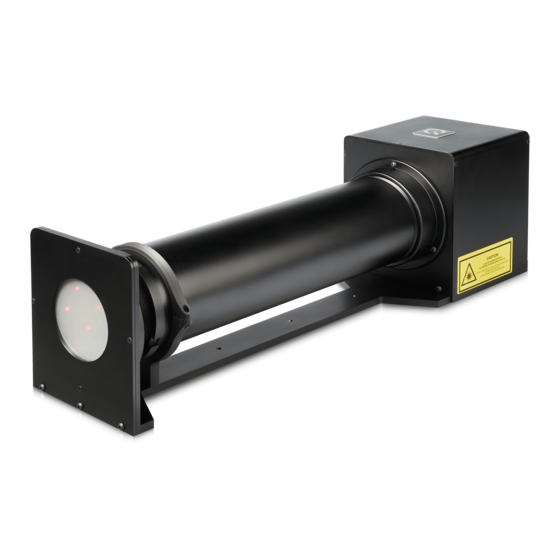
GEOCAL/GEOCAL XL consists of an illuminating hardware device and software for geometric calibration of camera systems. The GEOCAL software is used for calculating the calibration parameters from a single image taken with a camera system of the point grid generated by the GEOCAL hardware device. •... -
Page 5: Getting Started
The power socket and the main power switch are located on the back side of the device next to the USB type B socket. Connect GEOCAL / GEOCAL XL to a power outlet and switch it on. Please note that the blue LED next to the power switch indicates that the power line is active and that GEOCAL is ready for operation. -
Page 6: Operating Instructions Hardware
PNG and JPEG (lossy) are also supported. If you convert RAW image data to another format, ensure the image is debayered in the process. The autofocus must be turned off. Since GEOCAL / GEOCAL XL uses a collimated light beam virtually originating from infinity, the appropriate focus distance will be near infinity. Using manual focus, ensure the camera is focused on the light points. -
Page 7: Camera Position And Suitable Lenses
The top side of GEOCAL / GEOCAL XL and the top side of the camera must have the same orientation. A rotation of the camera around the optical axis of approx. +/- 2° will be tolerable. -
Page 8: Exposure
Do not change the camera's orientation between images because the points would no longer be aligned to one another through multiple images. Image Engineering Seite 8 von 19... -
Page 9: Differences Between Geocal And Geocal Xl
4 DIFFERENCES BETWEEN GEOCAL AND GEOCAL XL The key difference between GEOCAL XL and the standard GEOCAL is the physical size of the diffractive optical element (DOE) that generates the point grid. While the standard GEOCAL has a usable diameter of 77 mm, the GEOCAL XL provides a functional diameter of 155 mm. -
Page 10: Operating Instructions Software
5 OPERATING INSTRUCTIONS SOFTWARE The GEOCAL software lets you completely calibrate your camera system in a matter of seconds. The results can be saved as CSV or XML files. Installing GEOCAL software • Execute the GEOCAL installer (GEOCAL_Vx.x.x.exe, 64 bit) and follow the instructions. - Page 11 To use a custom value, write "true" instead of "false" and change the value ("0.1" in this example) as desired. The new value will be used in every calibration until you set the "Use" flag back to "false" again. Image Engineering Seite 11 von 19...
-
Page 12: Loading Images For Analysis
The following file types are supported (debayered images): .TIFF, .JPG, .PNG Images for analysis must be taken so that the point grid fills the sensor completely. 5.3.1 Delete images Right-click on the selected image in the list to open a delete option. Image Engineering Seite 12 von 19... -
Page 13: Image Analysis
(the brightest point in the center of the grid). Adjust the ROI size so that it contains only one point. The four remaining ROIs must be positioned on the four points closest to the 0 diffraction order, Image Engineering Seite 13 von 19... -
Page 14: Saving Results
Then click File → Save result → Save XML or Save CSV → navigate to the desired location → click Save If you selected multiple images, all results would be saved in one CSV or XML file. Image Engineering Seite 14 von 19... -
Page 15: Export Grids
The browser displays logging data for each action in the "Logging" section of the user interface. If errors occur, this can be helpful. The software also has a status bar at the bottom, where error messages from the API are displayed directly. Image Engineering Seite 15 von 19... -
Page 16: Quit
To exit the software, click File → Quit (ctrl+q) or simply close the window. TRADEMARK AND COPYRIGHT Trademarks Windows is a registered trademark of Microsoft Corp., Copyright Information See separate Terms and Conditions document. Image Engineering Seite 16 von 19... -
Page 17: Additional Information
Power circuit modification for production line use If you plan to use your GEOCAL / GEOCAL XL on a production line, we offer the option of modifying the unit to eliminate the need to press the switch to turn it on and off. After the modification, moving the switch to the "ON"... - Page 18 Usable FoV GEOCAL: approx. 575 mm x 144 mm x 170 mm Dimensions (l x w x h) GEOCAL XL: approx. 850 mm x 244 mm x 270 mm GEOCAL: 3 x M5x0,8 tapped holes in the base plate Mounting points GEOCAL XL: 10 x M5x0,8 tapped holes in the base plate 7.2.2...
- Page 19 GEOCAL XL: approx. 10 kg Operating conditions 15 - 35°C Requirements on the device under test (DUT) GEOCAL: max. diameter of the camera lens: 77 mm Max. dimensions GEOCAL XL: max. diameter of the camera lens: 155mm Usable FoV Approx. 30 – 180° (deviating values will have to be tested)
Need help?
Do you have a question about the GEOCAL and is the answer not in the manual?
Questions and answers